Get in touch with Zhenling Company

![Shop-Floor Carbon Steel CNC Machining Guide [2026]](https://zhenlingmetal.com/wp-content/uploads/2026/08/carbon-steel-cnc-machining-handbook-r2-featured.png)
Updated August 2026
Carbon Steel CNC Machining is predictable only after the material callout, supplied condition, feature geometry, cutting setup, and inspection method are defined. This handbook shows how to turn those inputs into an initial process, read the evidence produced by the cut, and stop before a generic rule becomes an expensive assumption.
Direct answer: Carbon steel is machinable, but the family name doesn’t set the process. Resolve the specification and condition, calculate from sourced inputs, then verify chips, load, finish, temperature, and dimensions before releasing the setup.
Quick Specs for Process Planning
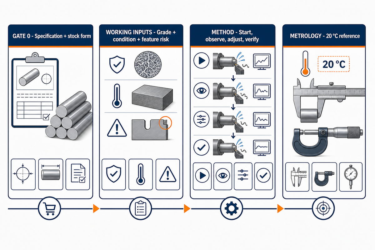
Gate 0
Specification, stock form, purchase requirements
Specification, stock form, purchase requirements
Three working inputs
Grade, condition, feature risk
Grade, condition, feature risk
Parameter method
Start, observe, adjust, verify
Start, observe, adjust, verify
Measurement reference
20 °C for dimensional metrology
20 °C for dimensional metrology
Key Points
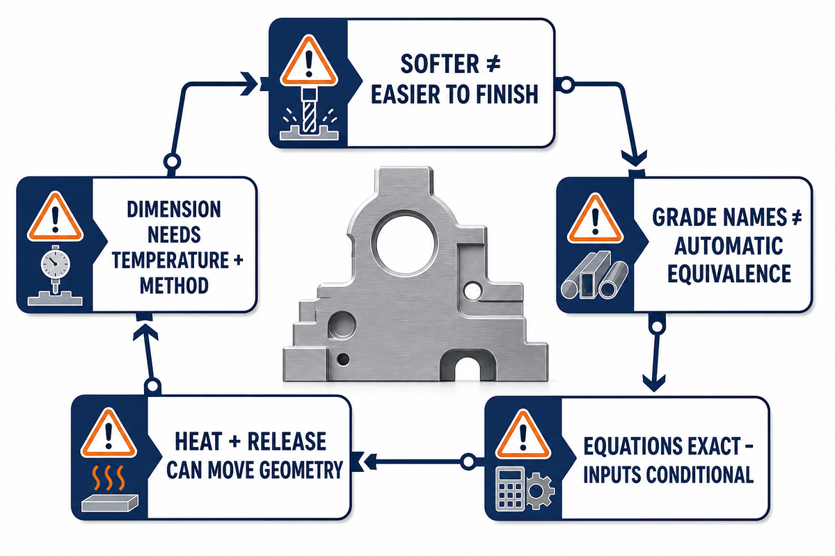
- A nominally softer steel is not automatically easier to finish.
- A36, 1018, 1045, 20#, and 45# are not automatic equivalents.
- Speed and feed equations are arithmetic; their inputs are conditional.
- Heat treatment and clamping release can change both hardness and geometry.
- A measured dimension is incomplete without temperature and method context.
Is Carbon Steel Machinable? What Actually Controls It
Carbon steel is machinable, but no single machinability label predicts every grade, batch, condition, and operation. Carbon level, microstructure, inclusions, hardness, product form, tool engagement, rigidity, and the required finish can move the same job from routine cutting to unstable wear or torn surfaces.
Start with the material definition. ASTM A108-24 covers cold-finished carbon and alloy steel bars in straight lengths or coils and recognizes purchaser-specified supplementary requirements. ASTM A29/A29M-23 also makes the purchase order and individual product specification controlling inputs.
| Input | Why it changes the cut | Evidence to obtain |
|---|---|---|
| Specification and form | Defines what the grade name actually controls | Drawing, purchase order, mill certificate |
| Hardness and condition | Changes force, wear, heat, and chip response | Condition callout and verified hardness |
| Microstructure and inclusions | Can alter abrasion and built-up-edge behavior | Batch record or trial-cut evidence |
| Feature geometry | Sets engagement, deflection, heat path, and datum risk | Drawing, setup plan, stock-removal map |
Shop-floor consequence: “easy to cut” and “easy to hold size and finish” are different questions. Even moderate-power material removal may produce long chips, a built-up edge, burrs, or a finish that changes as the edge loads.
Low-, Medium-, and High-Carbon Steel Are Not One Machining Input
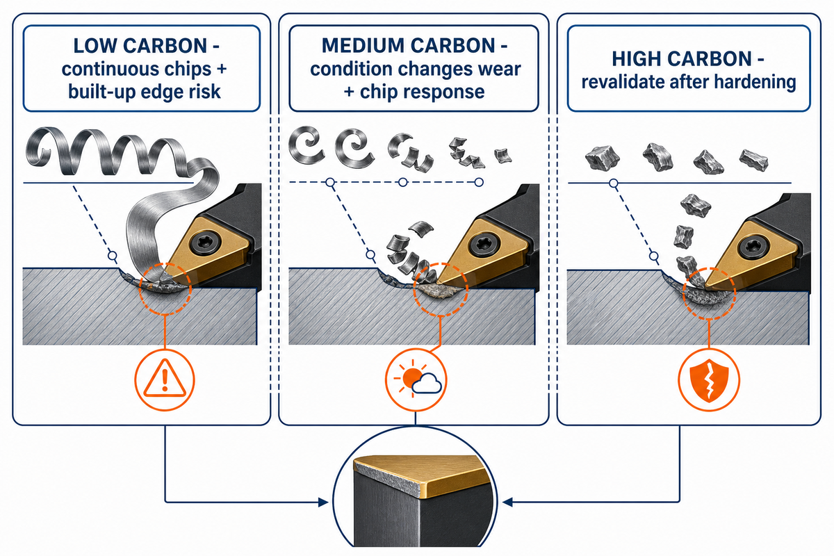
Low-, medium-, and high-carbon labels describe broad composition families, not ready-to-run cutting instructions. As carbon content and heat-treated condition change, strength, hardness, ductility, chip formation, edge loading, and finishing risk can change in different directions, so a family name should trigger questions rather than a fixed ranking.
Low-carbon workpieces can be ductile enough to form continuous chips and a built-up edge. The Precision Machined Products Association connects steel-bar machinability to cold work, thermal treatment, and chemistry rather than carbon label alone. Harder medium-carbon conditions may raise tool-wear risk while producing a more manageable chip in a particular setup. High-carbon material can enter another risk class after hardening, but the actual response still depends on microstructure, tool material, engagement, and interruption.
What Is the Difference Between Low-Carbon and Medium-Carbon Steel for Machining?
Low-carbon steel generally retains more ductility, which can make chip breaking and surface control difficult even when cutting forces seem manageable. Medium-carbon steel can offer a different balance of chip formation, strength, and wear, especially after normalization or heat treatment. Neither family should be assigned a speed, feed, or finish expectation until grade, condition, hardness, and operation are known.
The boundary near eutectoid composition is not a shop parameter. ASTM A1033-18(2023) defines 0.8% carbon for eutectoid carbon steel within its practice and notes that alloying elements affect the value. That is a reminder to keep standards definitions inside their stated scope when planning precision work.
Common mistake: using carbon content as a one-axis score. Whether the search says mild steel machining or machining high carbon steel, supplied microstructure and feature geometry determine whether the next problem is chip control, wear, deflection, or thermal movement.
1018, 1045, and A36: A Grade-and-Condition Decision Matrix
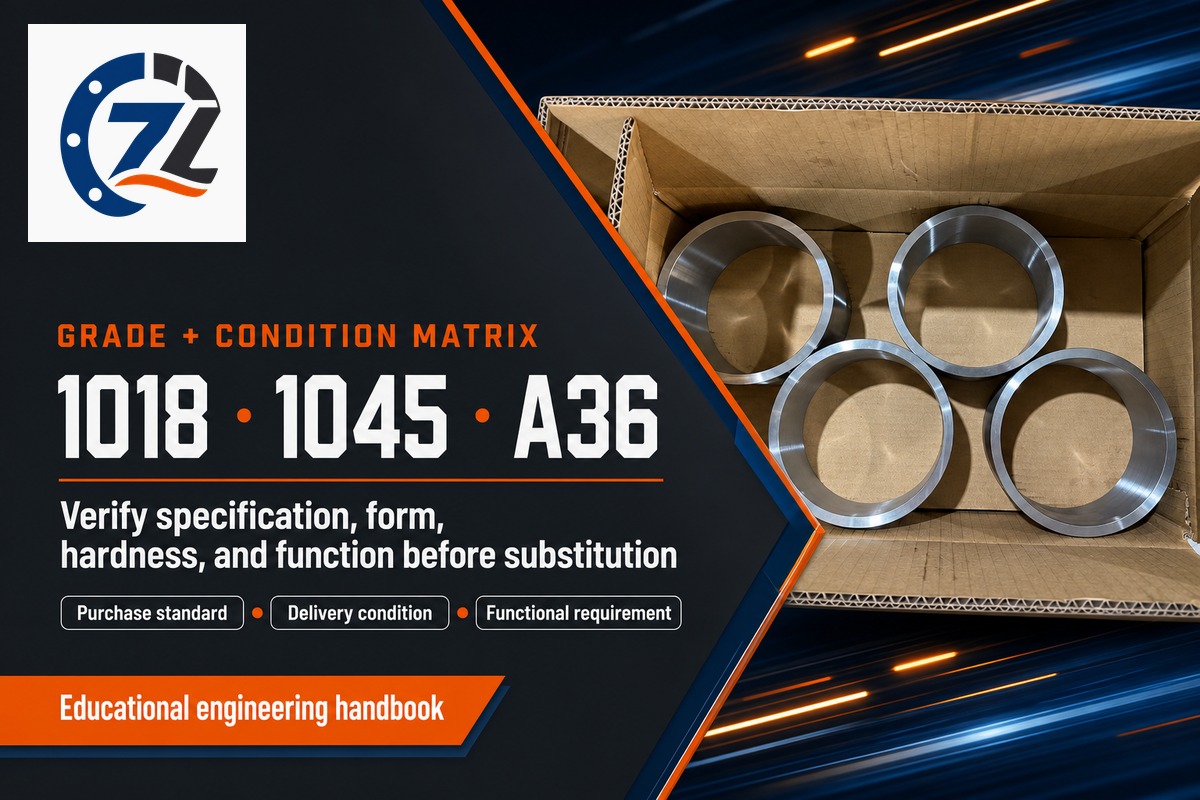
SAE 1018, SAE 1045, and ASTM A36 should be compared through their governing specification, product form, delivery condition, hardness, and functional requirement. A36 is a structural product specification, while 1018 and 1045 are familiar grade designations; none becomes an automatic substitute for another on a machined drawing.
| Callout | Useful first interpretation | Verify before cutting | Not a substitute for |
|---|---|---|---|
| 1018 | Low-carbon grade shorthand | Standard, form, cold/hot condition, hardness | A complete purchase specification |
| 1045 | Medium-carbon grade shorthand | Treatment, hardness range, stock form | A guaranteed machinability class |
| A36 | Structural shapes, plates, or bars within ASTM scope | Product form and supplementary requirements | SAE 1018 by name alone |
| 20# / 45# | Company-reported material experience | Controlling national standard and certificate | Automatic 1018/1045 equivalence |
The ASTM A36/A36M-19 scope covers structural-quality shapes, plates, and bars and says supplementary requirements apply when the order specifies them. That product-form context is why a material matrix should show unresolved purchasing inputs instead of declaring a winner.
Which Carbon Steel Grade Is the Most Machinable?
No one grade “cuts best.” Free-machining compositions may improve chip control yet conflict with welding or corrosion-resistance requirements. Familiar low-carbon grades may cut with modest force but still produce an inconsistent finish in a flexible setup. Select the material from the complete functional specification, including tensile strength, durability, and any required high-strength condition, then refine the precision process for the verified stock.
Selection scenario: a buyer requests “A36 or 1018” for a turned shaft because both appear to be mild steel. Its drawing also requires a stable bearing seat and later welding. Correct next steps resolve the product specification, condition, weld requirement, certificate, and finish-critical diameter before anyone approves a substitution; choosing the cheaper label is not enough.
The 5-Input Machining Compass: Specification to Feature Risk
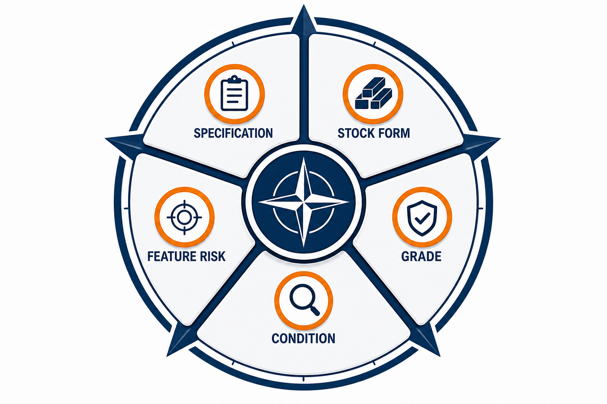
The 5-Input Machining Compass starts with governing specification and stock form, then adds grade, condition, and feature risk. Together, those five inputs form a minimum process-selection model for support, engagement, sequence, datum transfer, and inspection planning.
Key takeaway
Pass Gate 0 for specification and stock form, then use the input compass to choose a testable starting route—not to promise an outcome.
| Decision row | Question | If unresolved | Limitations / Not suitable for |
|---|---|---|---|
| 1. Specification | Which standard controls? | Stop substitution | Grade-name-only approval |
| 2. Stock form | Bar, plate, shape, forging? | Confirm product route | Mixed-form assumptions |
| 3. Grade | What chemistry/property callout? | Resolve certificate | Cross-standard equivalence |
| 4. Delivery condition | Hot rolled, cold finished, normalized? | Hold parameters | Family-average data |
| 5. Hardness | Required and actual range? | Measure or document | Unverified treated stock |
| 6. Batch evidence | Any inclusion or wear shift? | Run a controlled trial | Assuming chemistry tells all |
| 7. Thin feature | Will release or heat move it? | Plan staged removal | One-pass finishing |
| 8. Interrupted cut | Does engagement cycle? | Revisit edge strength | Continuous-cut assumptions |
| 9. Datum transfer | Will the part be reclamped? | Define verification points | Single-setup certainty |
| 10. Inspection | At what temperature and state? | Align the method | Unconditioned comparison |
Batch evidence belongs outside the promise. In 2025, a Wear journal article compared two C38 micro-alloyed steel batches with similar nominal chemistry and found different tool-wear responses; the less-machinable batch had less ferrite, higher hardness, and more abrasive nitrides.
Verification overlay: the input compass routes the first process review; it is not a complete material model. Keep heat-lot identity, measured hardness, ferrite/pearlite balance, inclusion population, and trial-wear evidence as a separate overlay. Do not bury batch uncertainty inside the single word “condition.”
Use the input compass twice: first when planning the trial, then again when chips, wear, finish, or inspection results disagree with the expected behavior. Treat a mismatch as evidence to recheck an input, not as permission to force the original assumption.
How to Set Cutting Speed and Feed Without Treating a Chart as a Promise
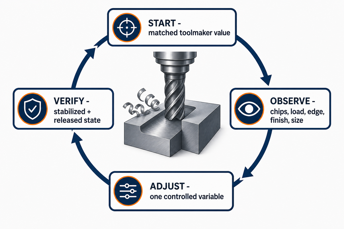
Set cutting speed and feed by separating formula arithmetic from input selection. Handbooks can calculate spindle speed and table feed exactly from declared values, but they cannot choose a safe starting value without the grade, hardness, tool, coating, engagement, coolant plan, rigidity, machine limit, and feature risk.
Published models illustrate why the inputs must travel with the number. An ASME turning paper derives cutting-force relationships from named feed, depth, tool radius, and steel inputs. A separate EN8 dry-milling study reports its 10 mm tool and 36-test design before comparing results. Neither makes its values universal; both show the minimum context needed before reuse.
Metric milling relationships
n = (vc × 1000) ÷ (π × D)
vf = fz × z × n
In these relationships, n is spindle speed in rpm, vc is cutting speed in m/min, D is effective cutting diameter in mm, vf is table feed in mm/min, fz is feed per tooth in mm/tooth, and z is the effective tooth count. Sandvik’s formula reference also emphasizes effective diameter and engagement.
Worked arithmetic example, not a cutting recommendation: suppose an engineer has independently approved a hypothetical 100 m/min cutting speed, a 10 mm effective diameter, four effective teeth, and 0.05 mm/tooth. This calculation gives n = (100 × 1000) ÷ (π × 10) ≈ 3,183 rpm, then vf = 0.05 × 4 × 3,183 ≈ 637 mm/min.
Those numbers prove only the arithmetic. Before cutting, confirm that 3,183 rpm and 637 mm/min are compatible with the actual insert or end mill, workpiece condition, radial and axial engagement, holder, machine torque, coolant strategy, workholding, and feature. Changing the effective diameter changes spindle speed even if the nominal tool body is unchanged.
Start–Observe–Adjust–Verify Cutting Parameter Loop
- Start: use a toolmaker value whose material group, hardness, geometry, and operation match the setup.
- Observe: record chips, sound, spindle load, edge condition, temperature pattern, burr, finish, and size.
- Adjust: change one controlled variable in response to a named symptom.
- Verify: repeat inspection after thermal stabilization and any unclamping or datum transfer.
On a new job, the first surface may look good while spindle load climbs across successive parts. Copying the original chart value forward hides the signal. Instead, the loop pauses for edge inspection, chip comparison, coolant delivery, and engagement review before the next adjustment.
Build a Trial Record That Another Shift Can Reproduce
A useful trial record separates declared inputs from observed results. Record the material specification, heat or batch identity, product form, certificate condition, measured hardness, machine and holder, tool designation, edge preparation, coating, and insert or cutter life state. Then record cutting speed in m/min, spindle speed in rpm, feed in mm/min, feed per tooth in mm/tooth, depth of cut in mm, radial engagement in mm or %, axial engagement in mm, coolant concentration in %, part temperature in °C, and the exact point at which the tool was inspected. For example, the earlier hypothetical calculation would be transcribed as 100 m/min, 3,183 rpm, 637 mm/min, 0.05 mm/tooth, 10 mm effective diameter, 1 mm axial engagement, four effective teeth, and 23 °C if that was the observed part temperature; these values remain arithmetic examples, not starting recommendations. Results should include chip form, spindle load trend, sound or vibration observation, burr location, surface-texture method, critical dimensions, measurement instrument, datum condition, and whether the part was clamped, released, warm, or thermally stable. This does not turn one trial into a universal recipe. It makes the evidence traceable enough to compare the next batch, tool edge, feature, or controlled parameter change without confusing memory with process data.
Tooling and Chip Control for Turning and Milling
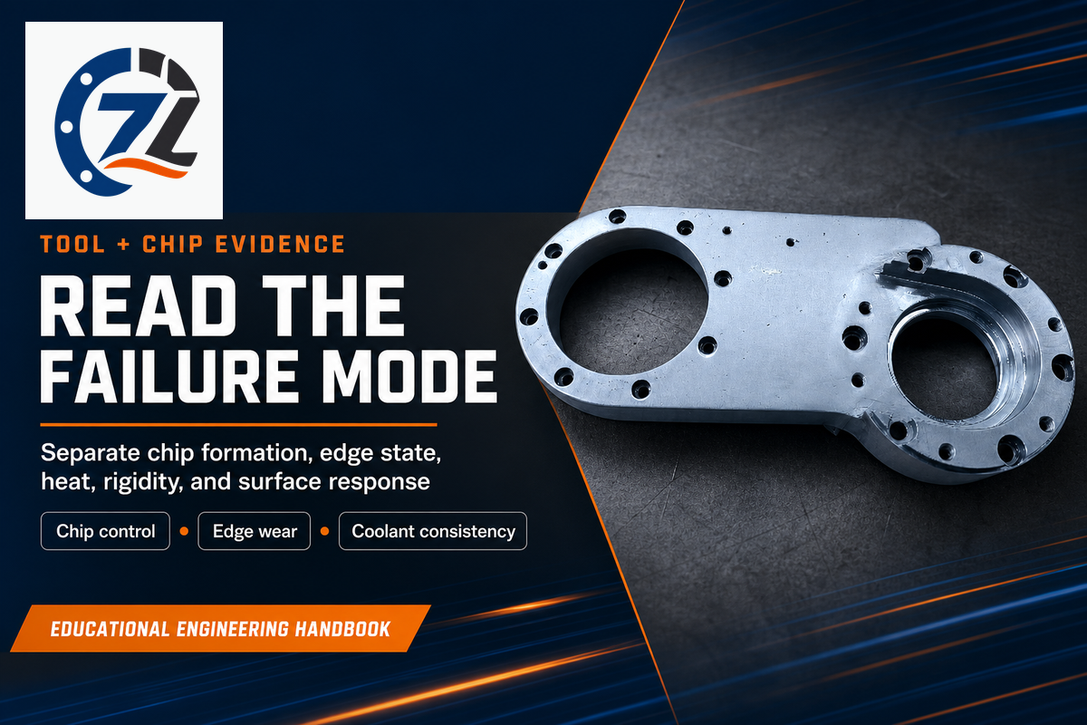
Tooling and chip control for carbon steel should be selected around the operation and observed failure mode, not the material family alone. Turning needs stable chip formation and evacuation; milling adds cyclic engagement and chip recutting. Edge geometry, chipbreaker, nose radius, coating, coolant, and workholding must operate as one system.
Turning: Read the Chip and the Edge Together
Long chips can point toward insufficient chip breaking, but the correct response may involve feed, depth of cut, chipbreaker geometry, entering angle, or workpiece diameter. A built-up edge can damage finish and alter the effective cutting edge, while a larger nose radius can increase radial force on a slender shaft.
Milling: Control Engagement and Recutting
CNC milling exposes the edge to entry and exit cycles. Excessive radial engagement, poor evacuation, runout, or a weak setup can make a reasonable formula produce chatter, recutting, or uneven wear. Check the actual engagement and effective cutter diameter before blaming carbon content.
Sandvik’s turning troubleshooting matrix assigns different actions to long chips, difficult chip breaking, burrs, vibration, flank wear, notch wear, crater wear, plastic deformation, built-up edge, thermal cracking, and chipping. That structure is more defensible than “raise speed” as a universal cure.
Contributors to a Practical Machinist discussion proposed different causes for a poor finish in 1018, including edge geometry, nose radius, rigidity, depth, speed, feed, and cutting fluid. Their disagreement is the useful signal: no isolated forum value is a universal prescription.
Coolant safety boundary: fluid choice and delivery affect cutting, but metalworking-fluid mist, skin contact, and splashes are also occupational-exposure questions. NIOSH guidance identifies respiratory and skin concerns. Use the current safety data sheet, machine enclosure, ventilation, maintenance, and site exposure-control program; this handbook does not prescribe a universal fluid or give medical advice.
Heat Treatment, Hardness, and Distortion: Sequence Before You Finish
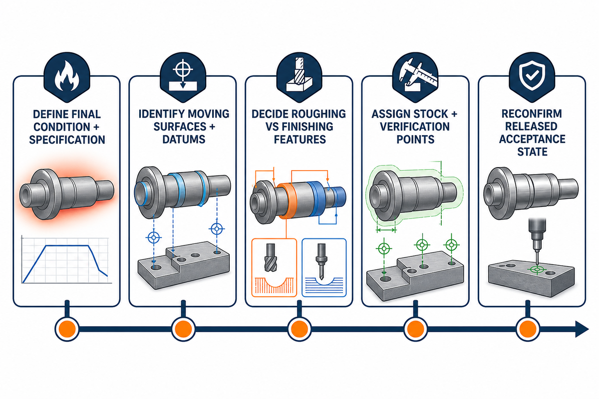
Heat treatment can change hardness, microstructure, residual stress, and geometry, so roughing, treatment or stress relief, finish stock, final machining, and inspection must be planned as one route. No universal allowance or sequence applies across carbon-steel grades, section thicknesses, quench methods, feature geometry, and governing specifications. This extends the tooling and coolant decisions above into the rest of the manufacturing route.
ASTM A1033-18(2023) uses high-speed dilatometry to quantify phase-transformation dimensional change in hypoeutectoid carbon and low-alloy steels. Its stated purpose includes data for predicting microstructures, properties, and distortion, while noting sensitivity to chemical composition and austenite grain size.
A Purdue experimental study quenched AISI 1080 cylinders in water and two polymer-based fluids and measured temperature, residual-stress, and hardness distributions. Because geometry and quench route are part of the evidence, the result cannot be transferred into a generic allowance.
- Define the required final material condition and the governing treatment specification.
- Identify surfaces and datums likely to move when stock, clamps, or stress are released.
- Decide which features are rough-machined before treatment and which remain for finishing.
- Assign finish stock and verification points from drawing-specific evidence, not a handbook default.
- Reconfirm hardness, datum state, surface condition, and inspection temperature before acceptance.
Where a contract invokes stress relief, scope matters. AMS2759/11B, revised in July 2025, establishes thermal stress-relief requirements for parts made from named steel groups, including carbon and low-alloy steels, in conjunction with AMS2759. It is not a general heat-treatment recipe or a distortion-prediction standard.
“Using higher-quality tool steel might not always be the answer.”
Hedrick’s examples concern tool steel, grinding, and wire EDM, so their temperatures and remedies do not transfer to this guide. Only a narrower point transfers: a visually acceptable surface can conceal process-induced thermal or stress damage, making sequence and verification part of quality.
Sequence scenario: a thin ring is roughed close to final size, heat-treated, then released from a rigid fixture. If roundness changes, increasing the finish pass cannot recover missing stock or redefine the datum. Accordingly, the route must assign pre-treatment stock, unclamped checks, final datum establishment, and acceptance timing before production begins.
Surface Finish and Dimensional Stability Need a Verification Loop
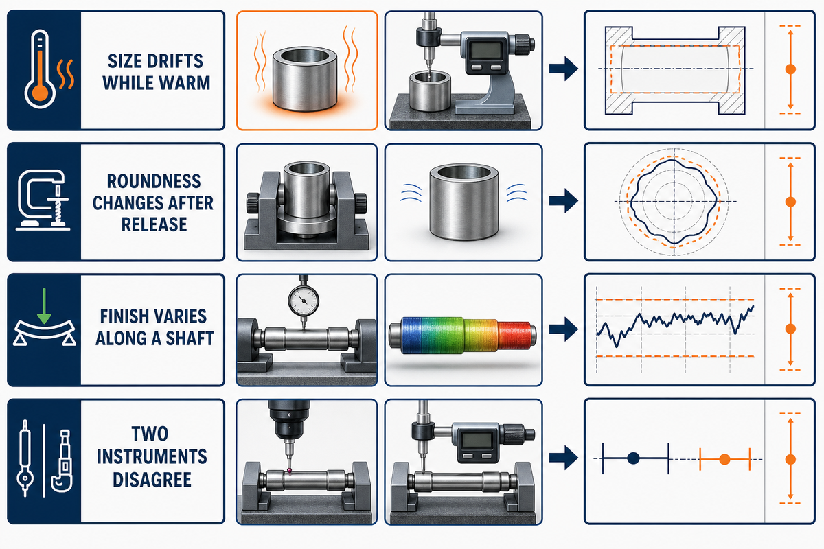
Surface finish and dimensional stability are verified outcomes, not detached machine capabilities. Tool state, heat, rigidity, stock-removal balance, burrs, datum transfer, clamping release, thermal equilibrium, reference temperature, instrument capability, and acceptance method must describe the same part state before a measured value can settle the requirement.
NIST’s Engineering Metrology Toolbox uses 20 °C as the dimensional reference temperature. Its example shows a 100 mm steel gage block at 23 °C requiring about 3.5 µm (135 µin) of thermal correction; uncertainty in the expansion coefficient adds about 0.3 µm (12 µin).
Keep four evidence layers separate: the drawing’s surface specification, the reported measurement parameters, instrument calibration or verification, and traceability plus uncertainty. ISO 25178-700:2022 addresses calibration, adjustment, and verification of areal topography measuring instruments. It supports the instrument layer; it does not replace the drawing’s acceptance operator or prove that a measured surface is functionally acceptable.
| Observed result | Mechanism to check | Verification evidence |
|---|---|---|
| Size drifts while warm | Part/instrument temperature | Stabilized temperature record |
| Roundness changes after release | Clamping stress or stock imbalance | Clamped and free-state checks |
| Finish varies along a shaft | Deflection, edge loading, built-up edge | Tool/finish map by position |
| Two instruments disagree | Method, force, resolution, datum | Measurement-system review |
A Current Standards-Watch Signal
ISO/CD 21920-3 Edition 2 entered committee-draft consultation in June 2026 for surface-texture profile specification operators and is intended to replace ISO 21920-3:2021. It remains under development, so engineers should verify the operative edition required by the contract date rather than treating the draft as published replacement guidance.
Metrology scenario: a shaft checks oversize immediately after turning but approaches nominal size after temperature stabilizes. First ask whether part temperature, instrument temperature, reference condition, datum, and measurement uncertainty were controlled, not whether to offset the tool. An offset applied to a thermal artifact can make the cooled part wrong.
Carbon Steel Machining Troubleshooting: Symptom to Adjustment
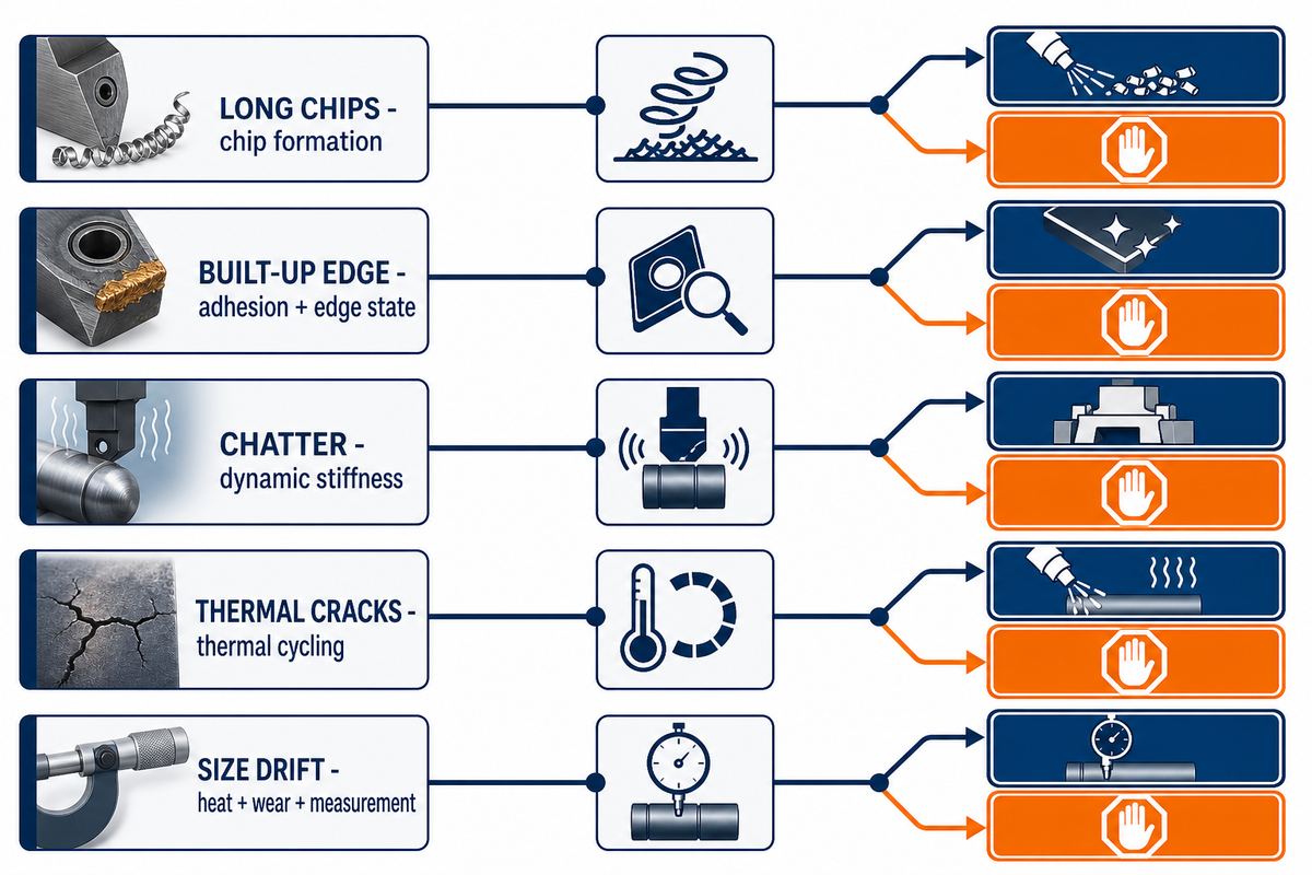
Carbon steel machining troubleshooting should begin with the visible symptom, then separate material, tool, engagement, rigidity, heat, chip evacuation, and measurement causes. Change one controlled variable, inspect the result, and escalate when the material condition, datum state, or governing requirement is uncertain instead of tuning around unknown inputs.
| Symptom | Likely cause class | First check | Possible controlled adjustment | Limitations / stop condition |
|---|---|---|---|---|
| Long chips | Chip formation | Feed, depth, chipbreaker | Adjust within toolmaker window | Stop if chip safety is uncontrolled |
| Built-up edge | Adhesion/edge state | Edge, speed, fluid delivery | Change one input and reinspect | Do not hide it with polishing |
| Chatter | Dynamic stiffness | Overhang, support, engagement | Shorten or alter engagement | Stop if feature deflects |
| Burr growth | Edge wear/material exit | Tool state and exit support | Refresh edge or route | Do not redefine acceptance |
| Rapid flank wear | Abrasion/thermal load | Batch, hardness, speed | Revalidate grade/conditions | Stop on unexplained batch shift |
| Edge chipping | Impact/weak edge | Interruption and runout | Revisit geometry/entry | Stop before cascading failure |
| Thermal cracks | Thermal cycling | Coolant consistency | Stabilize thermal strategy | Do not alternate blindly |
| Taper | Deflection/alignment | Support and tool force | Reduce force or improve support | Stop if datum is unstable |
| Size drift | Heat/wear/measurement | Temperature and edge trend | Correct verified cause only | Stop if uncertainty exceeds margin |
| Movement after release | Residual/clamping stress | Free-state geometry | Replan sequence and stock | Do not offset a released part |
Do
- Name the symptom before changing a parameter.
- Change one controlled variable.
- Record chips, wear, load, finish, and size together.
Don’t
- Copy an isolated forum value.
- Tune around unknown hardness or batch condition.
- Use polishing to conceal a cutting defect.
When not to keep adjusting: stop when the material certificate, actual hardness, heat-treatment route, datum state, feature requirement, or measurement system is unresolved. More parameter changes create more variables; they do not turn missing evidence into process knowledge.
When the Handbook Stops and Drawing-Specific Review Begins
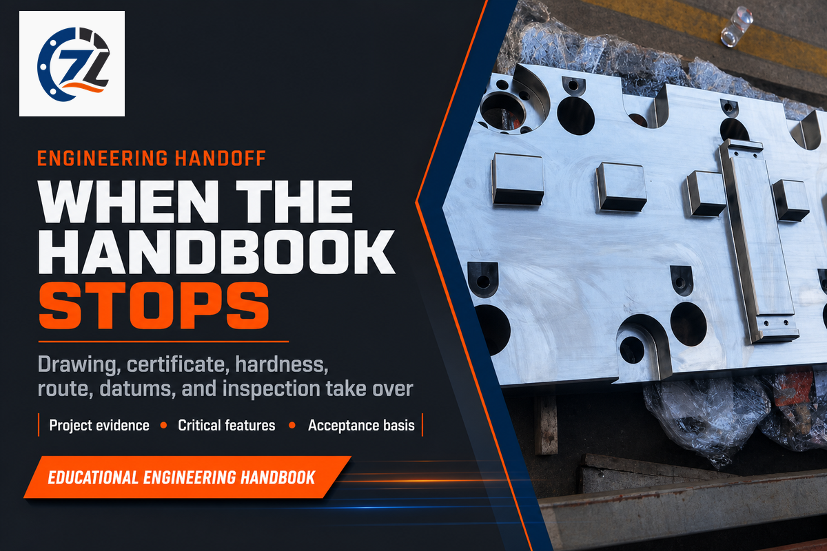
A generic handbook should stop when the answer depends on the drawing, material certificate, final hardness, heat-treatment route, datum strategy, inspection method, critical feature, or service environment. Pressure, temperature, corrosion, welding, fatigue, and traceability requirements require project-specific engineering and the applicable contractual or code route.
- The grade or national standard is ambiguous.
- A proposed substitution crosses product forms or standards.
- Hardness is specified but the delivered condition is unverified.
- A thin wall, ring, long shaft, deep cavity, or interrupted feature may move or deflect.
- Heat treatment, welding, coating, or plating occurs after machining.
- Surface texture or tolerance acceptance depends on a named standard edition.
- The part serves pressure, elevated-temperature, corrosive, or safety-relevant duty.
Shanghai Zhenling Hardware reports experience machining 20# and 45# carbon steels and operating turning, milling, grinding, boring, drilling, wire-cutting, and multi-axis resources. That is company-supplied context for carbon steel part review, not an independent precision tolerance, tool-life, hardness, certification, or pressure-performance benchmark.
Search and Supplier Terminology: Keep Labels Separate From Process Evidence
Supplier labels such as precision machining, five-axis machining, custom parts, or advanced equipment describe a category, not a cutting condition. Resolve them to the governing specification, product form, delivery condition, certificate, hardness, geometry, and inspection state. Equipment lists cannot prove tolerance, finish, tool life, or a process window.
When those project inputs are ready, continue with a drawing-specific carbon steel review. The phrase “CNC machining service” and searches for carbon steel machining services, quick turn CNC machining, a machining instant quote, or “request a quote” belong to that commercial page; this handbook intentionally does not duplicate its supplier-capability, pricing, lead-time, or conversion role. This article is limited to grade comparison, machinability, tooling and chip control, distortion, measurement, and troubleshooting questions; it is not a supplier-selection page.
Frequently Asked Questions
Can carbon steel components be finished or coated after machining?
Short answer
Yes, when the grade, surface preparation, coating system, and final requirements are compatible. Plan for coating thickness, masking, edge condition, and post-process inspection. Threads, bores, sealing faces, and datums may need protection or restoration. Put any required cleaning, baking, or verification step on the controlled route, and accept the part in its specified post-finish state rather than at the machine. Check the applicable finishing specification before production.
Is coolant required when cutting steel?
Short answer
Not for every operation. Toolmaker guidance, tool material, coating, speed, engagement, chip evacuation, finish, and thermal strategy determine whether a dry, minimum-quantity, or flooded route is suitable. If fluid is used, delivery must be consistent; intermittent cooling can worsen some failures. Also follow the current safety data sheet and the workplace program for mist, skin contact, housekeeping, and fluid maintenance. Confirm compatibility with coatings, seals, and downstream cleaning requirements.
What tools are used to cut steel on a CNC?
Short answer
Common choices include carbide turning inserts, solid or indexable end mills, drills, boring tools, reamers, threading tools, and grinding wheels. The correct substrate, coating, geometry, chipbreaker, edge preparation, and holder depend on grade, hardness, interruption, feature, and machine rigidity. Choose from the toolmaker’s matching material and operation window, then verify chips, wear, load, finish, and size. For thin or interrupted features, holder rigidity and reach can dominate the choice.
Can you CNC machine steel?
Short answer
Yes. CNC turning, milling, drilling, boring, grinding, and related processes can machine many steel grades. The viable route depends on material condition, hardness, feature geometry, tooling, machine capability, and inspection requirements.
Does A36 machine the same as 1018?
Short answer
No automatic equivalence should be assumed. ASTM A36 is a structural product specification, while 1018 is a familiar grade designation that still needs a governing standard and delivery condition. Compare certificate, product form, hardness, feature requirement, welding route, and trial evidence before approving a substitution or reusing parameters. Even if both stocks cut successfully, batch condition, section size, mill history, scale, and feature geometry can change chip formation, burr behavior, finish, and tool wear. Preserve the approved specification and substitution decision separately from the machining setup.
What should change when carbon steel is hardened?
Short answer
Revalidate the entire route: actual hardness, microstructure, tool material and geometry, engagement, machine rigidity, heat generation, stock allowance, finishing process, and inspection state. Don’t apply an annealed-condition chart to hardened stock. Confirm whether hardness is a drawing requirement, certificate value, or measured result, and record the method. Recheck the toolmaker material group, edge preparation, chipbreaker, coating, speed, feed, depth, coolant strategy, and allowable wear. If treatment occurs between roughing and finishing, stage stock removal, re-establish datums, and inspect thin or sensitive features in the released, thermally stable state. For interrupted cuts, confirm that edge strength and entry strategy match the repeated impact rather than a continuous-cut assumption. Stop if the treatment specification, case/core condition, or remaining stock cannot support the final feature. Record the revised trial so the next batch is compared against evidence, not memory.
Transparency note: This handbook separates official standards, peer-reviewed or university research, toolmaker guidance, trade-press context, forum experience, patent provenance, and company-supplied information. Demonstration calculations are labeled and aren’t starting-parameter recommendations.
Additional Current Review Sources
- Three Key Factors to Understand Machinability of Carbon and Alloy Steel — Precision Machined Products Association
- Cutting-force relationships for turning — ASME PVP proceedings
- EN8 dry-milling experimental study — NCBI-hosted full article
- Metal Working Fluids — National Institute for Occupational Safety and Health
- ISO 25178-700:2022 — International Organization for Standardization
References & Sources
- ASTM A108-24 — ASTM International
- ASTM A29/A29M-23 — ASTM International
- ASTM A36/A36M-19 — ASTM International
- Batch-to-batch microstructural variations and tool wear in C38 steel — Chalmers University of Technology / Wear
- ASTM A1033-18(2023) — ASTM International
- Simulation of quenching and induction heat treatment with experimental verification — Purdue University
- AMS2759/11B: Stress Relief of Steel Parts — SAE International
- Tips for grinding and wire machining tool steel — The Fabricator
- Engineering Metrology Toolbox FAQ — National Institute of Standards and Technology
- ISO/CD 21920-3 Edition 2 project record — International Organization for Standardization
- US4061494A patent record — Nippon Steel assignee record via Google Patents
![Shop-Floor Carbon Steel CNC Machining Guide [2026]](https://zhenlingmetal.com/wp-content/uploads/2026/08/carbon-steel-cnc-machining-handbook-r2-featured-150x150.png)