Get in touch with Zhenling Company

PTFE (Teflon) CNC Machining is the process of cutting solid fluoropolymer stock into precision parts while controlling softness, thermal movement and cold flow. Searches for Teflon machining or machined Teflon parts usually refer to this same stock-removal process. Grade, stock form, fixture pressure and inspection temperature all affect the released dimension, so the drawing and RFQ should define them before a supplier commits to tolerance.
PTFE (often called Teflon) CNC machining is the process of cutting solid PTFE stock into precision parts. Its shop-floor behavior is easy to misunderstand. This article explores Teflon in its solid form: machined bar, rod and sheet stock used in the manufacture of custom PTFE parts and components – not the non-stick coating most people think of when the name Teflon comes to mind. Buyers assume it machines just like another engineering plastic. It doesn’t. Whether you search for it as PTFE CNC machining, CNC machining Teflon, or simply machining Teflon, the underlying material behavior – and the tolerance problems it causes – stays the same. Here we’ll examine what actually makes PTFE different to machine, how stock form and filler material affect your part, why tolerances wander once the part leaves the machine, and what you should look for before you put a drawing in front of a supplier – whether a fluoropolymer specialist or a general plastic CNC machining services supplier.
What Makes PTFE Different to Machine? (Softness, Cold Flow & Thermal Expansion)
Polytetrafluoroethylene (PTFE) is a fluoropolymer – a fully fluorinated fluorocarbon made of repeating units of carbon and fluorine – that provides a low friction coefficient, broad chemical resistance, low thermal conductance and high thermal resistance, and a useful working range often cited at approximately -200 °C to 260 °C (-330 °F to 500 °F), subject to grade and application limits. These properties make PTFE useful where chemical resistance, water resistance, electrical insulation or thermal stability matters.
Among materials for CNC machining, these properties of PTFE make it a candidate when excellent chemical resistance and physical and electrical insulation properties matter, although PTFE applications still require grade-specific validation. Although often described as chemically inert, the material still needs its chemical, temperature and concentration envelope checked for the specified grade.
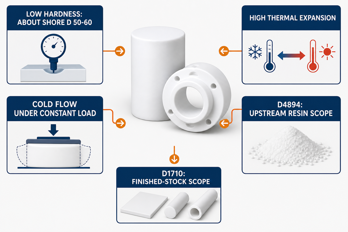
Understanding these unique properties is the beginning of successfully machining PTFE, which, from a mechanical point of view, differs from the metals or rigid plastics typically found on a CNC shop floor. Three properties drive recurring challenges in this guide: low hardness (one cited practitioner guide reports about Shore D 50-60), a high coefficient of thermal expansion, and a tendency to cold-flow (slowly deform under a constant mechanical load even at room temperature). PTFE is compatible with many industrial chemicals, but the exact grade, temperature, concentration and exposure conditions still need an application-specific compatibility check. In short, Teflon machinability comes down to managing softness, thermal expansion and cold flow together, not any single property in isolation.
The cited ASTM source set distinguishes granular molding or ram-extrusion resin from finished extruded rod, heavy-walled tubing and basic shapes. For teams machining thermoplastics, this guide therefore treats the D4894 resin scope as upstream and the D1710 finished-stock scope as the solid input to CNC turning or milling. Those standards listings do not establish whether a particular supplier uses thermoplastic injection molding or any other intermediate stock-forming step; verify the actual processing route separately.
| PTFE Behavior | Machining Consequence | Control to Validate |
|---|---|---|
| Thermal expansion (published range about 100-200 ×10-6/°C) | A warm feature changes size as it returns to inspection temperature | Part-temperature measurement and grade-specific compensation |
| Low hardness | Dull tooling or excessive cutting force can drag or tear the surface | Sharp geometry, light finishing cuts and first-article inspection |
| Cold flow under sustained load | Clamping or assembly stress can change the released dimension over time | Low-force workholding plus a defined stabilization and inspection state |
Is PTFE Hard to Machine?
Machining PTFE isn’t hard the way metal is hard – it’s soft, has low rigidity and is prone to cold flow, so holding dimension is the real challenge, not cutting the material itself. Soft does not mean easy to machine to tolerance. A sharp tool cuts through PTFE stock with little trouble; the issue shows up downstream, as parts can relax, wander, or shrink once out of the fixture.
Practitioner sources describe out-of-spec risk when PTFE is treated like a rigid plastic and finished in one operation without checking temperature or relaxation. Their recommended controls include separating roughing from finishing where the tolerance warrants it, limiting clamping force and defining the temperature at which the part will be inspected.
PTFE Stock Forms: Choosing Rod, Bar and Sheet Before You Cut
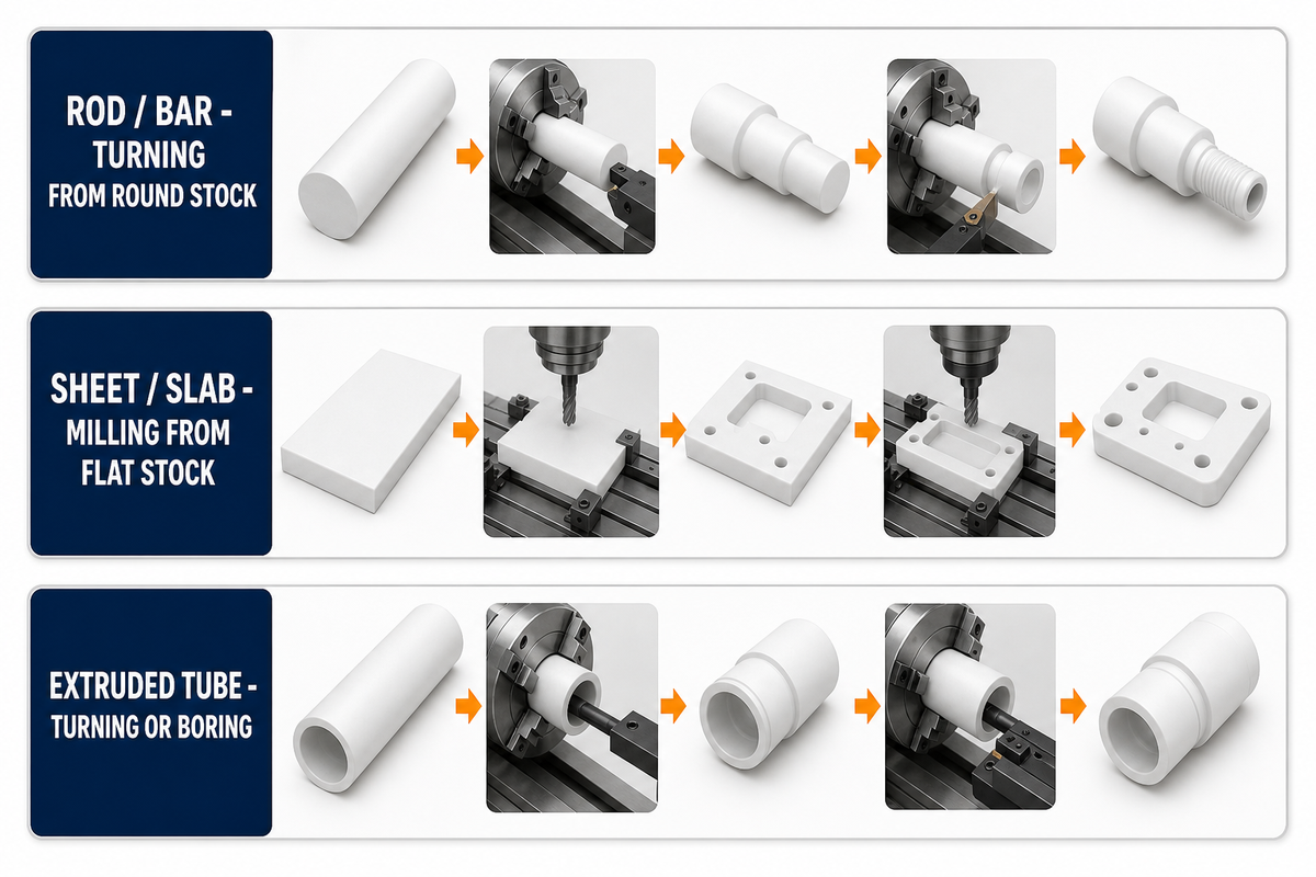
As a geometry-based planning heuristic, start stock-form selection from the finished part rather than from a generic preference for rod or sheet. Rod and bar commonly provide the round starting envelope for turned geometry, sheet provides a flat envelope for milled geometry, and tube can reduce the amount of material removed for some sleeves or bushings. The actual choice still depends on available sizes, allowance, grade, certification and the supplier’s process plan; the ASTM stock-form scope alone does not prove the lowest-waste or lowest-cost route.
When a drawing allows more than one material for CNC machining, compare chemistry and temperature requirements before choosing the grade and stock form. That sequence reduces avoidable waste in PTFE machined parts without treating rod, bar or sheet as a universal default.
| Stock Form | Typical Machining Route | Best-Suited Part Type |
|---|---|---|
| Rod / bar | Candidate: turning from round stock | Often screened for rotational seals, bushings, valve seats and spacers |
| Sheet / slab | Candidate: milling from flat stock | Often screened for flat gaskets, insulation blocks and wear plates |
| Extruded tube | Candidate: turning or boring from tubular stock | Often screened for sleeves, liners and heavy-walled bushings |
Sourcing stock to ASTM D1710 — the relevant specification for extruded PTFE rod, heavy-walled tubing and basic shapes — gives buyers a traceable material baseline. The cited scope uses the categories virgin resin and reprocessed resin. If a certificate instead says “reground PTFE” or uses other terminology, require the supplier to map it to the ordered ASTM category; do not assume the terms are equivalent. Any certification still needs to match the ordered resin category, grade and stock form, and it does not replace finished-part inspection.
For rod or bar parts with rotational features, check the supplier’s turning capacity against stock diameter, part length and inspection requirements. Sealing diameters commonly begin with turning from round stock, while non-rotational features may need a secondary milling operation. For related capability context, see our CNC turning service page; verify the equipment and usable envelope for the actual drawing instead of inferring them from this link.
Machining Process & Techniques: Tooling, Speeds/Feeds and Workholding
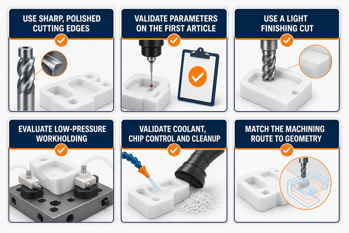
For teams working with PTFE, the process window differs from metal’s, so reusing metal-cutting parameters without validation can damage first-article finish or dimensions. “CNC machining and milling” may appear as a broad service label, but turning and milling setups both need to account for PTFE’s softness, thermal movement and cold flow. Below are qualified starting points that still need validation for the actual grade, diameter, tool geometry and fixture:
Source context: American Machinist’s overview of PTFE behavior.
- Tools. Practitioner guidance favors sharp, polished cutting edges with positive rake and adequate relief so the tool shears instead of drags the soft material. Inspect surface finishes on the first article before locking the tool and parameter plan. Carbide is a common starting point; PCD becomes a tool-life option for abrasive filled grades rather than a universal requirement.
- Spindle speed & feed. Select parameters for the actual PTFE grade, diameter, tool geometry and setup rather than carrying over metal values. Aim to limit frictional heat and material drag while maintaining a clean shear cut. Because published recommendations vary, validate the selected parameters on the first article instead of treating lower numbers as universal.
- Depth of cut. Use a light finishing cut when thin walls or small features would otherwise see excessive cutting force, then verify the released dimension after the part has stabilized.
- Workholding. Because PTFE is soft and exhibits cold flow, excessive vise or collet pressure can deform a part before the cut is complete. Evaluate low-pressure soft jaws, vacuum support or another distributed-contact fixture for tight-tolerance geometry, then confirm the dimension after release.
- Coolant & chip control. Coolant contamination is a documented PTFE machining failure mode. Do not treat “pressurized air and spray mists” or “water-soluble coolants” as universal recommendations. A process combined with water-soluble coolants still needs validation for chip evacuation, heat control, fluid compatibility, cleanup and the part’s cleanliness requirements.
- Milling vs. turning. Rotational geometry usually starts from rod, bar or tube on a lathe; CNC milling usually starts from sheet or slab for flat or prismatic geometry. Tool geometry still needs a first-article check because a configuration that works on one grade and diameter is not automatically transferable to another.
PTFE Machining Tolerances: Why Cold Flow and Thermal Expansion Move Your Numbers
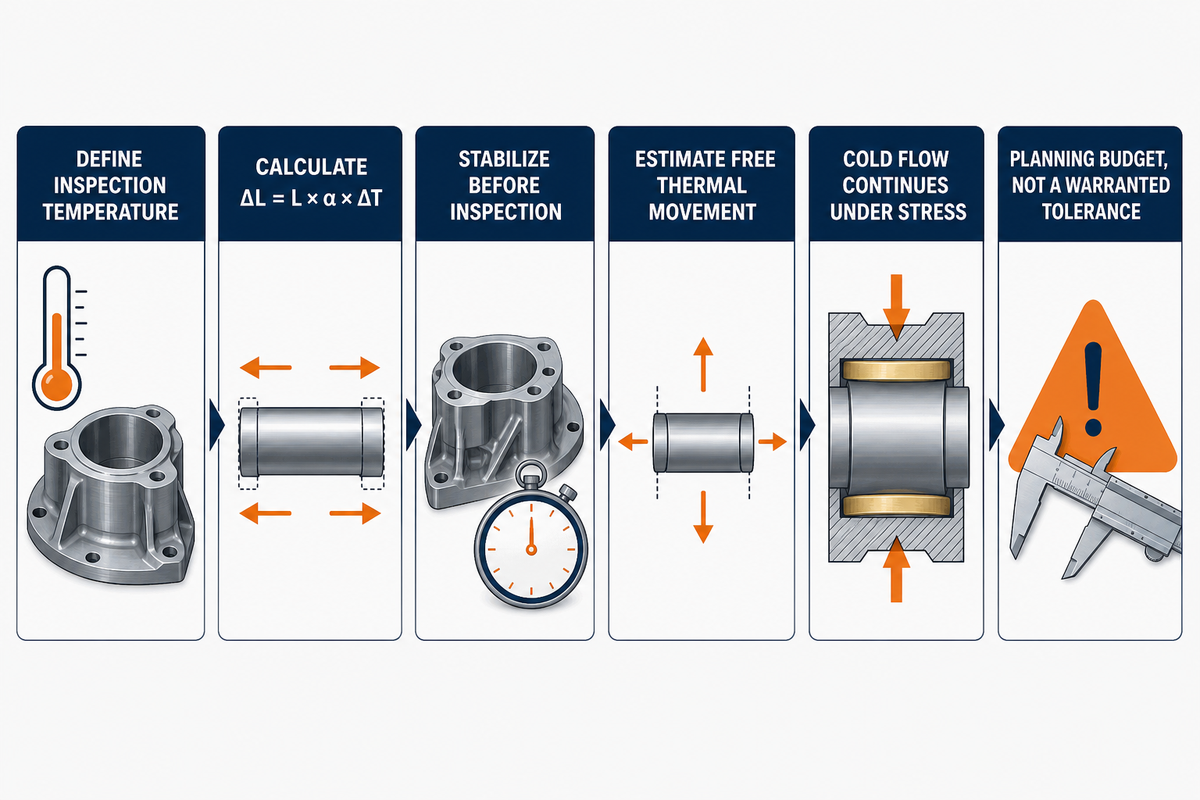
A common assumption about PTFE — “it can’t hold tight tolerances” — isn’t always accurate. Uncompensated thermal expansion and cold flow do move a part’s dimensions after it leaves the machine; that part is true. What’s not true is that this movement is unavoidable. Practitioner guides report about ±0.02 mm on controlled PTFE rotational-feature examples using temperature measurement and compensated programming, while also citing about ±0.05 mm for unmanaged virgin PTFE. These figures are planning references for surface finishes and tolerances, not blanket capability promises.
Named framework 9-Row Thermal Expansion Tolerance Matrix. The table applies the linear-expansion relation ΔL = L × α × ΔT to three feature sizes and three temperature differences, using the published unfilled-PTFE planning range of 100-200×10-6/°C. It estimates free thermal movement only; fixture stress and time-dependent cold flow require separate evaluation.
| Feature Type | Wall Thickness Band | Temp. Delta (as-cut to ambient) | Estimated Dimensional Movement* |
|---|---|---|---|
| 25 mm OD, ID or length | Not used in the equilibrium calculation | 5°C | 0.0125-0.0250 mm |
| 25 mm OD, ID or length | Not used in the equilibrium calculation | 10°C | 0.0250-0.0500 mm |
| 25 mm OD, ID or length | Not used in the equilibrium calculation | 15°C | 0.0375-0.0750 mm |
| 50 mm OD, ID or length | Not used in the equilibrium calculation | 5°C | 0.0250-0.0500 mm |
| 50 mm OD, ID or length | Not used in the equilibrium calculation | 10°C | 0.0500-0.1000 mm |
| 50 mm OD, ID or length | Not used in the equilibrium calculation | 15°C | 0.0750-0.1500 mm |
| 100 mm OD, ID or length | Not used in the equilibrium calculation | 5°C | 0.0500-0.1000 mm |
| 100 mm OD, ID or length | Not used in the equilibrium calculation | 10°C | 0.1000-0.2000 mm |
| 100 mm OD, ID or length | Not used in the equilibrium calculation | 15°C | 0.1500-0.3000 mm |
*Arithmetic: movement = feature size × CTE × temperature difference. Direction depends on whether the part is warming or cooling and whether the controlled feature is an OD, ID or length. Wall thickness affects heating, cooling and stress response, but it does not change the equilibrium linear-expansion calculation. Treat the result as a planning budget, not a warranted tolerance, and confirm the actual grade’s data plus the agreed inspection temperature.
Worked example. Take a turned PTFE bushing with a 40 mm OD, measured at 32°C after finishing and inspected at 22°C, a 10°C difference. Applying the same 100-200×10-6/°C range gives 40 mm × 10°C × 0.0001-0.0002, or about 0.040-0.080 mm of free thermal movement. Against a ±0.02 mm print tolerance, that estimate is two to four times the one-sided tolerance allowance before fixture stress or cold flow is considered. The example shows why a supplier needs grade-specific thermal data, a defined inspection temperature and validated compensation rather than a universal offset.
Cold flow adds a slower-acting variable to thermal movement: under sustained clamping or assembly stress, PTFE can continue to creep after machining. Practitioner reports describe rough-machining tight features, allowing a defined relaxation interval and then finishing to size. The interval is process-specific and should be validated for the actual grade, geometry, stress state and inspection plan rather than copied from a single shop example.
Cold flow can continue after the spindle stops when the part remains under clamping or assembly pressure. For tight-tolerance work, define when the part will be released, stabilized and inspected instead of assuming the warm, clamped machine reading is the final condition.
— Process risk summarized from the cited practitioner sources
What Is the Tolerance of PTFE Machining?
Achievable tolerance depends on grade, geometry, workholding, temperature and inspection method. Commercial practitioner guides cite about ±0.05 mm for unmanaged virgin-PTFE examples and about ±0.02 mm for controlled rotational examples using thermal compensation. Those figures are sourcing benchmarks, not a general capability promise. Filled grades may reduce thermal or creep response, but the exact improvement must come from the specified compound’s data and the supplier’s validated process.
Where a drawing requires tight control, compare machine setup, temperature control and inspection method together. Our precision CNC machining page is a related internal navigation target, not evidence of an achievable PTFE tolerance. The actual drawing and process still require review.
PTFE Grades and Fillers: How Glass, Carbon and Bronze Filling Change Machinability
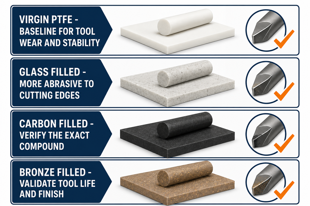
A drawing that says only “PTFE” leaves the supplier to infer whether the requirement is virgin material or a filled compound. Commercial grade guides distinguish glass-, carbon-, graphite-, bronze- and molybdenum-disulfide-filled formulations because each changes rigidity, wear, friction or chemical behavior. NASA’s cited technical brief also demonstrates the narrower point that a particular filled PTFE formulation can reduce thermal expansion materially; it does not establish one reduction factor for every commercial compound.
Filled grades can also be more abrasive to cutting tools, with glass fiber commonly identified as a source of faster edge wear than virgin PTFE. Supplier literature for different modified PTFE materials may use labels such as mechanical grade PTFE, improved mechanical properties, wear resistance, superior compressive strength and wear, or high resistance to wear. Those are vendor comparison phrases, not universal rankings; obtain the exact compound data sheet and validate tool life, compressive strength and wear resistance, and released dimensions on the intended geometry.
| Filler Type | Machinability Effect | Typical Wear/Tool Impact |
|---|---|---|
| Virgin / unfilled PTFE | Soft and susceptible to cold flow and tool drag | Baseline for comparing filler-related tool wear and stability |
| Glass fiber filled (15-25% by weight, common commercial grades) | Supplier guides describe greater stiffness and reduced creep for common compounds | More abrasive to cutting edges than virgin material |
| Carbon filled | Supplier guides describe improved rigidity, wear and electrical conductivity | Tool-life effect depends on the exact carbon compound |
| Bronze filled | Supplier guides describe improved compressive and wear behavior | Dense metal-filled compound; validate tool life and finish |
A located patent publication describes a nano-silica-modified PTFE formulation aimed at wear and creep performance. One dated patent does not establish a broad or current machining trend, so treat it as an example of formulation development rather than market evidence.
PTFE vs. UHMW, Delrin (POM) and PEEK: Machinability Compared
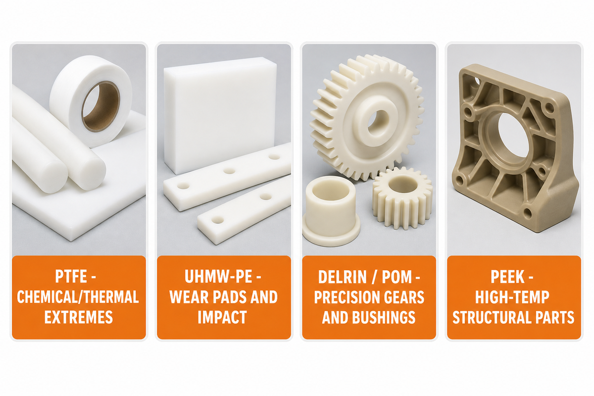
PTFE, UHMW-PE, acetal/POM and PEEK solve different combinations of chemical, temperature, friction, stiffness, wear and cost requirements. Materials described as similar to PTFE may match one property while differing sharply on another. A commercial comparison can screen candidates, but it cannot approve a substitute: the exact grade must be checked against the fluid, concentration, temperature, load and regulatory context. Use the table below as a planning prompt, then replace its approximate values with current manufacturer data for the shortlisted grade.
| Material | Machinability | Max Service Temp. | Relative Cost | Best-Fit Application |
|---|---|---|---|---|
| PTFE | Difficult (soft, cold-flows, thermal drift) | ~260°C | $15-40/kg | Chemical/thermal extremes, low-friction seals |
| UHMW-PE | Moderate (soft but less creep-prone than PTFE) | ~80-100°C | Low | Wear pads, low-cost slide surfaces, impact resistance |
| Delrin / Acetal (POM) | Easy (rigid, tight tolerances straightforward) | ~90-105°C | Low-moderate | Precision gears, bushings, structural plastic parts |
| PEEK | Moderate-difficult (hard, abrasive to tools, but dimensionally stable) | ~250°C | High | High-temp structural parts needing tight tolerance + strength |
Engineers often select PTFE when chemical resistance and low friction outweigh stiffness, tolerance stability and machining cost. Where that combination isn’t necessary, Delrin or UHMW-PE may be a more economical candidate, but the final choice still depends on the actual chemical, temperature, load and wear conditions.
Neither substitute is a universal cost-effective alternative for industries that face aggressive chemicals or high temperatures; the comparison is a screening step, not a material approval.
If the main design driver is tight tolerance, stiffness and straightforward machining rather than PTFE’s friction or chemical envelope, acetal/POM is one screening candidate; see our POM (Delrin/Acetal) CNC Machining Guide. Where high-temperature service and structural stiffness must coexist, PEEK CNC Machining is another candidate to compare. Neither statement is an approval without grade-specific compatibility and load data.
Common PTFE Machining Defects and How to Prevent Them
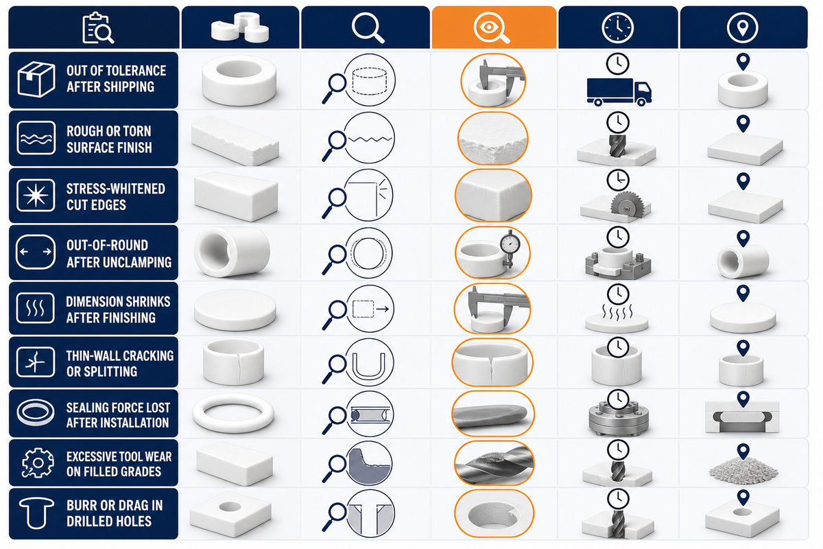
The symptoms below are a troubleshooting map assembled from published PTFE behavior and practitioner reports, not a record of Zhenling’s defect history. Each row is a hypothesis to test: inspection evidence still has to distinguish material relaxation, temperature, fixturing, tooling and design causes on the actual part.
Named framework 9-Row PTFE Defect-to-Root-Cause Matrix.
| Symptom | Root Cause | Fix |
|---|---|---|
| Part out of tolerance after shipping (measured in-spec at machine) | Cold flow / creep continuing after machining, especially under any residual clamping or assembly stress | Test a defined relaxation interval before the final pass; validate fixture pressure and the released inspection state |
| Rough, “furry” or torn surface finish | Dull tooling or metal-style cutting parameters dragging rather than shearing the material | Inspect edge sharpness and geometry; validate grade- and setup-specific cutting parameters on the first article |
| Whitening or stress-whitening along cut edges | Localized overheating or excessive cutting force at the tool contact point | Check heat and cutting force; test a lighter finishing cut and a validated chip-control strategy |
| Out-of-round or oval bore after unclamping | Excessive clamping force permanently deforming the soft material before release | Reduce or distribute clamping force, then remeasure after release; qualify the fixture on the first article |
| Dimension shrinks after finish pass, before shipping | Thermal contraction as the part cools from cutting temperature to ambient | Measure part temperature and test grade-specific compensation against the agreed inspection plan |
| Cracking or splitting of thin-walled features | Stress concentration from over-clamping or aggressive feed on a thin section | Reduce fixture and cutting load; validate the hole-making sequence on the first article |
| Sealing force lost weeks after installation | Cold flow under sustained compression, misdiagnosed as a machining defect months later | Review compression limits and compound creep data; evaluate a filled grade only with grade-specific evidence |
| Excessive tool wear on filled-grade parts | Abrasive filler content (glass fiber especially) accelerating edge wear | Track tool life and compare tool materials for the specified filled compound |
| Burr or drag on drilled/tapped holes | Chip packing and material drag in deep or small-diameter holes | Validate sharp drill geometry and a candidate chip-breaking cycle on the first article |
What Are the Downsides of PTFE?
PTFE’s main practical limitations in this machining context are low strength and stiffness relative to more rigid engineering plastics, wear concerns for some unfilled load cases and cold flow under sustained pressure. The importance of each limitation changes with grade, geometry, load, temperature and required service life.
These characteristics aren’t by themselves disqualifiers, but they do mean buyers choose PTFE primarily for its thermal and chemical properties rather than its structural rigidity. Designs should account for these behaviors through measures such as compression limits, a validated filled grade where wear or strength requires it, and an appropriate joining method.
Where Machined PTFE Parts Are Used: Seals, Bushings, Bearings and Valve Components
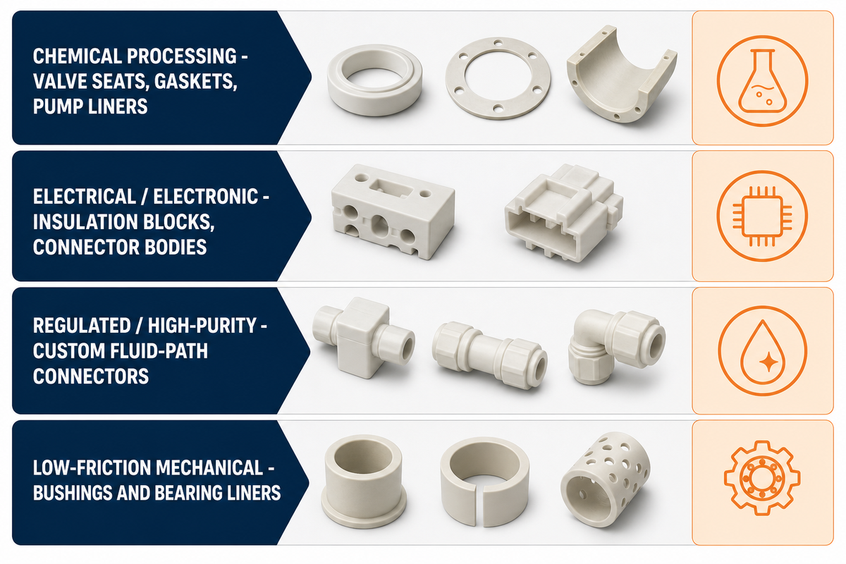
PTFE is screened for machined seals, bushings, bearings, valve components and insulators when low friction, electrical behavior, chemical compatibility or temperature capability matters. These are part-family examples, not proof that every PTFE grade is suitable for every industry listed below.
Source context: peer-reviewed PTFE material-property data.
For electronics and medical fluid-path parts, material selection still requires grade-specific checks for cleanliness, moisture behavior, chemical compatibility and the applicable regulatory requirements; the application label alone doesn’t prove suitability.
| Industry | Common Machined Parts | Key Property Required |
|---|---|---|
| Chemical processing | Valve seats, gaskets, pump liners | Chemical resistance to acids, bases, solvents |
| Electrical/electronic | Insulation blocks, connector bodies | Grade-specific dielectric data, temperature and geometry |
| Regulated or high-purity systems | Custom fluid-path connectors, valve components | Application-specific material compatibility, cleanliness and regulatory validation |
| Low-friction mechanical systems | Bushings, bearing liners, wear components | Load, creep, wear and lubrication conditions |
For related industry capability context, see Aerospace CNC Machining. This internal link is navigational only and does not replace application-specific PTFE grade approval or verify a part’s compliance.
What Drives the Cost of CNC-Machined PTFE Parts
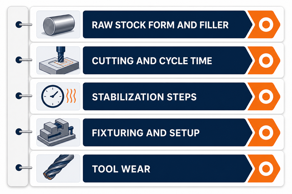
One commercial comparison places PTFE raw stock at roughly $15-40/kg, depending on form and filler content. Treat that range as a dated planning input rather than a current quote. Finished-part pricing also reflects cutting time, stabilization steps, fixturing, inspection and tool wear.
- Grade- and geometry-specific parameter selection can change cutting load, tool wear and cycle time.
- A roughing, relaxation and finishing sequence adds handling and elapsed shop time when the tolerance plan requires it.
- Filled-grade stock price and cutter wear vary with the specified compound and production quantity.
- Low-force or distributed-contact workholding can add fixture design and setup time.
- Temperature measurement, compensation trials and stabilized inspection add first-article engineering and quality-control time.
How to Evaluate a PTFE Machining Partner: A Buyer’s Checklist
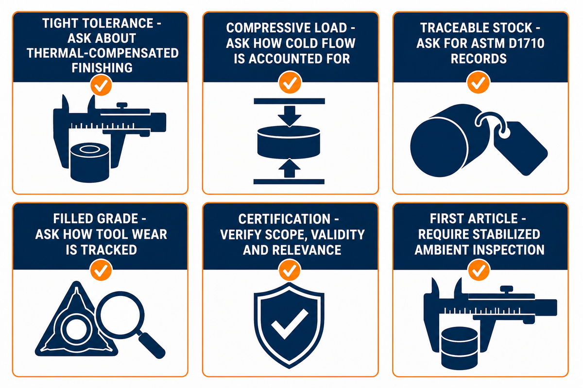
PTFE machining success depends on process rigor as well as machine capability, so ask any potential supplier how they manage the known behavior of this material, not just for an equipment list. Process controls, inspection state and material records are worth verifying before you commit a drawing.
| If Your Part Requires… | Ask Your Machinist About… |
|---|---|
| Tolerance tighter than ±0.05 mm | Whether they program a thermal-compensated finishing dimension and measure at stabilized ambient temperature |
| Sustained compressive load in service (e.g. a static seal) | How they account for long-term cold flow in the design tolerance, and whether a filled grade is recommended |
| Traceable, standard-conforming raw stock | Whether stock is sourced to ASTM D1710 (rod/tubing/shapes) and what mill certifications they retain |
| A filled grade (glass, carbon or bronze) | How they track tool wear and qualify tool material for the specified filled compound |
| Certification for export or regulated end use | The exact certificate, issuing body, scope, validity and relevance to the ordered part |
| A first article before a production run | Whether they measure and report dimensions at stabilized ambient temperature, not warm off the machine |
On facility and certification specifics: Shanghai Zhenling Hardware discloses that it operates an 8,000 sqm precision machining facility in Jiashan, Zhejiang, established in 2006, holds CE and ASME-applicable certifications, and exports approximately 80% of output to Europe, Singapore, the US and Australia. These are disclosed here as buyer-evaluation criteria: facility scale, certification, export track record — not as PTFE-specific performance claims.
If you already have a PTFE drawing, use our PTFE (Teflon) CNC Machining Services page as the commercial handoff for a scoped review. For first-party company background, see our About Us page. These links are navigation, not independent verification of capability, certification scope or suitability for a specific order.
Industry Standards for Machined PTFE: ASTM D1710, D4894 and What They Mean
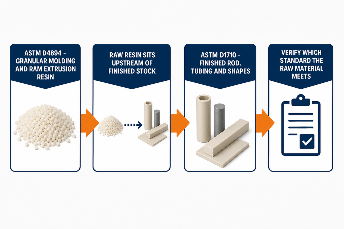
Two ASTM standards cover the PTFE finished-stock and upstream-resin scopes discussed here. ASTM D1710 covers extruded PTFE rod, heavy-walled tubing, and basic shapes made from virgin or reprocessed resin. ASTM D4894 covers PTFE granular molding and ram extrusion resins used to produce that stock in the first place; it sits one step upstream of D1710 in the supply chain, governing the raw resin rather than the finished extruded form.
| Standard | What It Covers | Status |
|---|---|---|
| ASTM D1710-15(2021) | Extruded PTFE rod, heavy-walled tubing and basic shapes (virgin or reprocessed resin) | Edition listed by the cited ASTM source: 2015, reaffirmed 2021 |
| ASTM D4894-19(2024) | PTFE granular molding and ram extrusion resins (upstream of D1710 finished stock) | Edition listed by the cited ASTM source: 2019, reapproved 2024 |
Ask which standard the raw material meets and keep the mill certification with the order record. That document helps identify the declared resin category and stock form, but it does not by itself prove finished-part quality or application suitability.
Q: Do PTFE and Teflon Mean the Same Thing on a Drawing?
Do not rely on either word alone: state PTFE plus the required grade, filler, resin category, stock form and applicable specification on the final drawing.
A drawing or RFQ that says only PTFE or Teflon does not define an interchangeable grade. State PTFE plus the required grade, filler percentage, virgin or reprocessed resin category, stock form and applicable specification. If a particular brand is mandatory, state that requirement separately and ask the supplier to confirm availability and certificate scope. Keep the supplier’s material certificate with the order record, and resolve any terminology that does not match the cited ASTM categories before approval.
Q: Can PTFE Material Be Machined?
Yes, PTFE is fully machinable with standard CNC equipment, but it needs process parameters tuned for its softness, thermal expansion and cold flow rather than the metal-cutting speeds and feeds a shop might default to first.
Yes — standard CNC mills and lathes can machine PTFE, although it behaves differently from metal because of its softness, high thermal expansion coefficient and capacity for cold flow under clamping pressure. A PTFE setup therefore needs grade-specific decisions for tool geometry, cutting parameters, workholding force and chip or coolant control rather than an untested transfer of metal-machining parameters.
Q: What Is PTFE?
PTFE is a fluoropolymer with low friction and broad chemical resistance; the cited ASTM listings distinguish upstream resin from finished rod, tubing and basic shapes used as machining stock.
PTFE (polytetrafluoroethylene) is a synthetic fluoropolymer with a repeating carbon-fluorine backbone, a very low coefficient of friction, broad chemical resistance and a useful operating range often cited at roughly -200°C to 260°C. The ASTM listings cited here distinguish upstream granular molding or ram-extrusion resin from finished extruded rod, tubing and basic shapes used as machining stock. Grade and application limits still control the usable temperature and chemical envelope.
Q: What Is CNC Machining?
CNC machining removes material from a solid block of stock using computer-guided cutting tools to produce a precise, custom part, following instructions generated directly from an electronic CAD design file.
CNC (Computer Numerical Control) machining is a subtractive process: computer-guided cutting tools remove material from a solid block of stock to produce a precise part straight from a CAD design file.
Q: How Does Acetal (POM) Compare With PTFE?
Acetal/POM is generally stiffer and easier to hold to tight tolerances, while PTFE is selected when low friction and chemical or thermal service matter more.
Acetal/POM and PTFE are different material families, so the choice should follow the service conditions rather than the familiar trade name on a request. Acetal/POM generally offers greater stiffness and more predictable tolerance control. Choose PTFE when low friction and a broader chemical or thermal envelope outweigh stiffness and machining cost. Confirm the exact grade against load, wear, chemical exposure and service temperature before approval, then record the approved grade and service limits on the drawing. See our POM (Delrin/Acetal) CNC machining guide for a more detailed comparison.
Q: Need Teflon (PTFE) CNC Machined Parts?
If your drawing is ready, submit it for a grade and tolerance review before requesting a scoped quote, with inspection conditions and application constraints stated in the RFQ.
If you already have a part drawing, define the grade, filler, stock form, tolerance, inspection temperature, quantity and application constraints before requesting a scoped review. Use our PTFE (Teflon) CNC machining services page as the commercial handoff, not as evidence that an unspecified tolerance or application has already been approved. For teams still comparing machinable plastic options broadly, treat PTFE as a distinct category rather than a drop-in swap for Delrin or PEEK.
Why We Write This
Zhenling prepared this guide from published standards, peer-reviewed research, practitioner sources and first-party company information. The references below are a selected reader-facing list rather than the complete claim-by-claim evidence record. That evidence frames drawing, material and supplier decisions without turning the selected list into a complete audit trail.
Statements about PTFE machinability, typical defects or material behavior rely on the documented evidence set; the article does not use undisclosed project histories as support.
References & Sources
- PTFE thermal and dielectric properties (Heliyon, Cell Press) peer-reviewed, hosted on NIH PMC
- Low-Thermal-Expansion Filled Polytetrafluoroethylene NASA Technical Reports Server
- ASTM D1710-15(2021) ASTM International official standard listing
- ASTM D4894-19(2024) ASTM International official standard listing
- CNC Processing of PTFE Materials: From Entry to Application Tirapid, practitioner machining guide (commercial source)
- How Do You Achieve ±0.02mm Accuracy When Machining PTFE and Teflon Parts? Hotean (commercial source)
- 7 PTFE Machining Mistakes to Avoid Advanced EMC (commercial source)
- PTFE machining properties Eng-Tips practitioner forum discussion