Get in touch with Zhenling Company

Updated August 2026
Inconel CNC Machining is rarely a one-speed, one-insert, or one-coolant phenomenon. Successful efforts begin with careful selection of alloy, manufacturing route, product form, heat-treatment state, feature geometry, cutting engagement, and acceptance requirements, not just a parameter from a chart or case history.
This guide explains which mechanical properties matter at the cut, why nickel-based superalloys concentrate heat, how work hardening and chip formation interact, how Inconel turning, CNC milling, drilling, and grinding differ, and how to recognize wear and dimensional drift. It is an informational framework, not a quotation page, capability statement, or drawing approval.
Inconel CNC Machining succeeds when the complete cutting system stays inside a verified evidence envelope. Match material route and condition, preserve cutting action, manage heat and chip exit, observe more than one signal, and verify the finished feature in its required state.
Key points before the first cut
- A discontinuous Inconel 718 drilling test lowered measured edge temperature while raising feed force, so interruption is a tradeoff rather than a simple penalty.
- Wrought and additively manufactured Alloy 718 can respond differently even when the nominal alloy name matches.
- Segmented chips may lower force in one regime yet increase force variation, wear, or surface risk in another.
- A published parameter is usable only with its alloy, condition, operation, tool, engagement, cooling, machine context, and measured outcome.
- Machining and dimensional inspection do not by themselves establish pressure-code conformity or part suitability.
| Lock before trial | Record | Do not substitute |
|---|---|---|
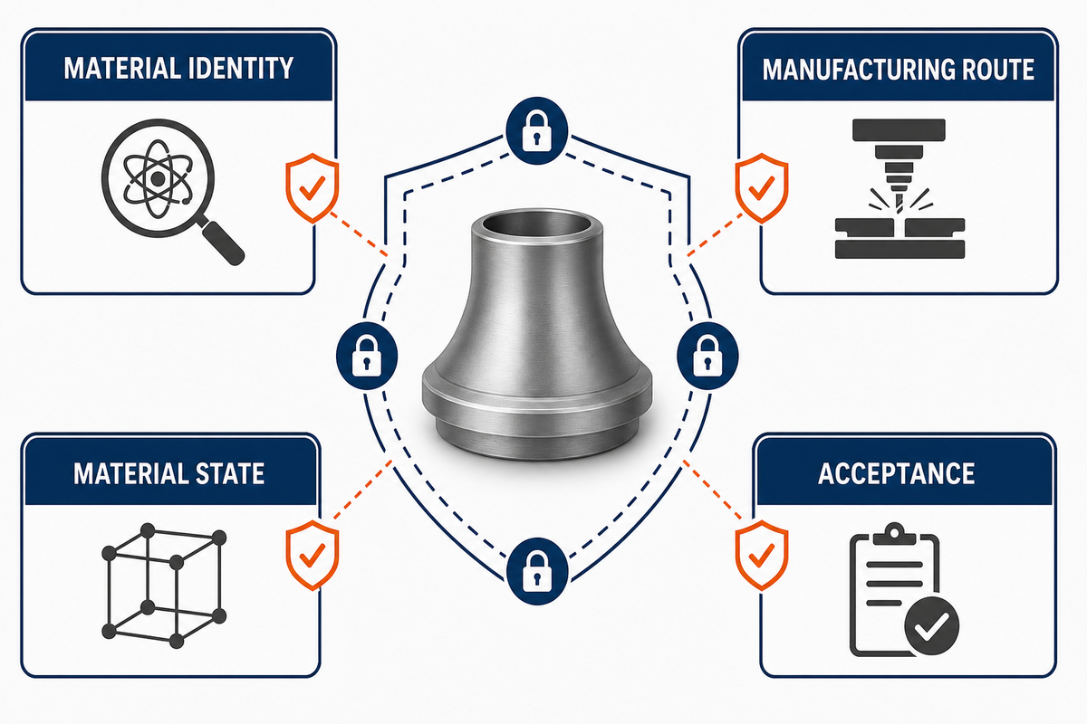
| Material identity | Alloy designation and governing specification | The word “Inconel” alone |
| Manufacturing route | Wrought, cast, powder route, or additive route | A matching nominal chemistry |
| Material state | Product form, heat treatment, hardness evidence, starting microstructure | An undocumented prior lot |
| Feature | Wall, reach, interruption, exit edge, datum, stock allowance | Machine-axis count |
| Cutting system | Substrate, coating, edge geometry, holder, runout, replacement threshold | A coating name |
| Cut | Speed, feed, depth of cut, radial engagement, entry, exit | One orphan number |
| Cooling and chips | Delivery point, flow state, chip exit, filtration, mist controls | “Flood” without observation |
| Acceptance | Part state, datum, instrument, coverage, surface requirement | A tolerance value without method |
1. Why Is Inconel So Difficult to Machine?
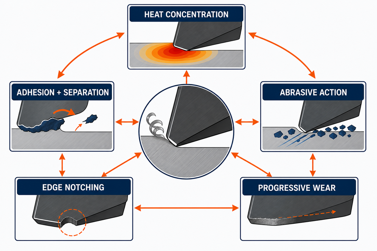
Inconel machining is difficult because retained strength, low heat dissipation, work hardening, adhesion, abrasive phases, and high cutting loads act together at the cutting edge; the relative importance of each mechanism changes with grade, condition, operation, engagement, tool system, and feature stiffness, so “hard material” is an incomplete diagnosis.
Peer-reviewed reviews of nickel-superalloy machining describe heat concentration near the tool, repeated adhesion and separation, abrasive action, edge notching, and progressive wear. High-temperature strength helps an alloy perform in demanding service, but during machining it also means the workpiece does not lose resistance as quickly as many common steels; depending on the setup, high strength at the cut may coincide with high cutting forces, rapid work hardening, or faster tool wear, so the cutting edge must carry mechanical load while heat remains localized.
Work hardening adds a location problem. Rubbing, repeated contact, or a damaged edge can leave the next pass cutting material whose near-surface state differs from the bulk. That doesn’t mean every bright rub mark proves hardening, or that a larger feed is always safer. It means the observation must be joined to load, chip, edge, and surface evidence before a correction is chosen. Both the 2022 tool-wear review and a broader 2023 Inconel machinability review support these coupled mechanisms.
A steel-derived rule can therefore fail even when the same machine and cutter style are used. Zhenling’s tool steel machining guide explains a different grade-condition-geometry logic; it is useful for comparison, not for transferring speeds or feeds into a nickel superalloy. No single machinability rating of Inconel or AISI machinability index can substitute for the grade-condition-operation evidence needed here.
First check: Separate the symptom from the cause. Record the chip, cutting edge, load trend, sound, surface pattern, and dimensional movement before describing the problem as hardness.
2. Match Inconel Grade, Route, and Material State to the Cut
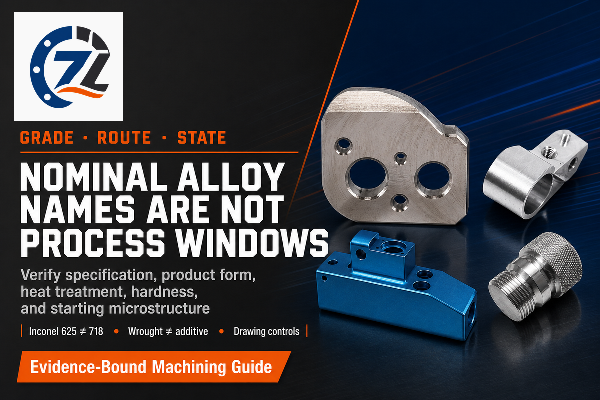
A valid machining brief for Inconel materials names the grade, specification, manufacturing route, product form, heat-treatment state, starting microstructure evidence, hardness when required, feature geometry, and acceptance plan. That brief keeps Inconel 625 and 718, wrought stock, cast stock, and additively manufactured stock from sharing a process window merely because they sit inside the Inconel family.
Official records show why condition language matters. ASTM lists B637-26 as active from April 16, 2026, with scope tied to specified precipitation-hardenable nickel-alloy rod, bar, forgings, and forging stock. SAE’s current panels identify AMS5662P as solution-treated Alloy 718 product forms and AMS5663P as solution-and-precipitation-treated forms. Those records—and nominal chromium or cobalt content—do not authorize substitution or approve a finished component.
Consider two blanks both labeled Alloy 718. One is wrought and supplied under a named solution-treated condition; the other is powder-bed-fusion material after a post-build route. One 2026 study compared as-built, hot-isostatically-pressed, heat-treated, and wrought material and found distinct microstructures and machining responses. Cemented carbide was more sensitive to condition in that test, while binderless cubic boron nitride behaved more consistently across the additive conditions. Those samples were small and cutting lengths short, so the useful decision is to add route and microstructure to the transfer checklist, not to declare one tool universally best.
In addition, the full Alloy 718 route comparison reported different roughness, residual-stress penetration, subsurface deformation, and tool wear. An earlier heat-treatment review likewise connects composition, production route, microstructure, and heat treatment to machinability.
Application labels set context, not approval. Inconel applications described as aerospace applications, gas turbine engine components, or chemical processing applications may emphasize different high-temperature or corrosion-service requirements, but phrases such as excellent corrosion resistance or oxidation resistance do not select a grade, prove service suitability, define the cut, or establish final assembly acceptance. Machining Inconel on a 5-axis center may solve access or datum-transfer problems; the axis count still doesn’t establish the tool, fixture, process window, or inspection result.
Use the site’s machining material options to compare the Inconel family, Hastelloy, and other material families, but let the governing drawing and material documents control the final grade and condition.
3. Use the Rub–Harden–Heat–Wear Interaction Map
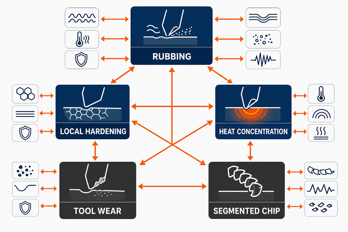
The Rub–Harden–Heat–Wear Interaction Map treats rubbing, local hardening, heat, tool wear, chip segmentation, and fracture as interacting paths rather than a fixed four-step cascade. With grade, route, and material state fixed, each path may reinforce load and damage, or a competing mechanism may reduce cutting force while creating a different surface, stability, or wear penalty.
Clean cutting action can deteriorate when the edge dulls, the tool deflects, or engagement falls below the effective chip-forming condition. More rubbing may increase heat and alter the next layer. Rising wear can then change geometry, contact length, chip flow, and load. Yet the sequence is not inevitable: localized thermal softening or fracture can change force and produce serrated chips before the assumed downstream stage appears.
| Node | Can increase | Can be countered by | Observe | Boundary |
|---|---|---|---|---|
| Rubbing | Contact heat, smearing, near-surface change | Restored edge condition or effective chip formation | Chip thickness, surface wipe, edge image | A shiny mark alone does not prove hardening |
| Local hardening | Next-pass load and notch risk | Route change that avoids recutting the affected layer | Load at re-entry, edge location, depth history | Bulk hardness does not locate the altered layer |
| Heat concentration | Adhesion, diffusion, edge softening | Chip removal and qualified coolant access | Edge temperature proxy, discoloration, wear location | Cooler is not automatically mechanically safer |
| Tool wear | Contact area, force variation, dimensional drift | A defined replacement threshold | Flank, notch, chipping, size trend | Predictable short life may beat random failure in one production case |
| Thermal softening | Shear localization | Strain and strain-rate hardening | Chip segmentation and force waveform | Lower force can coexist with surface or wear penalties |
| Fracture | Chip separation and force variation | Ductile flow under another condition | Crack path, chip root, surface damage | A broken chip is not proof of an acceptable surface |
| Segmented chip | Evacuation and periodic loading | A stable continuous chip in another regime | Segment pitch, evacuation, vibration | Segmentation does not always improve accuracy |
| Built-up material | Geometry change and tearing | A stable edge and verified cutting state | Edge deposit and transferred material | Deposit and coating failure require different evidence |
| Dimensional drift | Compensation pressure | Error-source isolation | Tool offset, thermal state, datum, independent measurement | Offsetting the wrong cause can hide the defect |
“The serrated or segmented chip phenomenon is desirable in reducing the level of cutting force.”
But this statement can represent just one desirable outcome—not the sum result. That work also covers dynamic force fluctuations, variations in finish and accuracy, and increasing tool wear. Accelerated tool wear remains a possible outcome to verify, not a guaranteed consequence of segmented chips. Therefore, a general analysis tool or a graphic such as this will lead one to investigate potential causes or effects, not prescribe results.
For comparison, a separate carbon steel machining guide may help readers see how chip and heat behavior changes with material family, but its process window must stay outside an Inconel setup.
4. Choose Turning, Milling, Drilling, or Grinding by Cut Continuity and Load
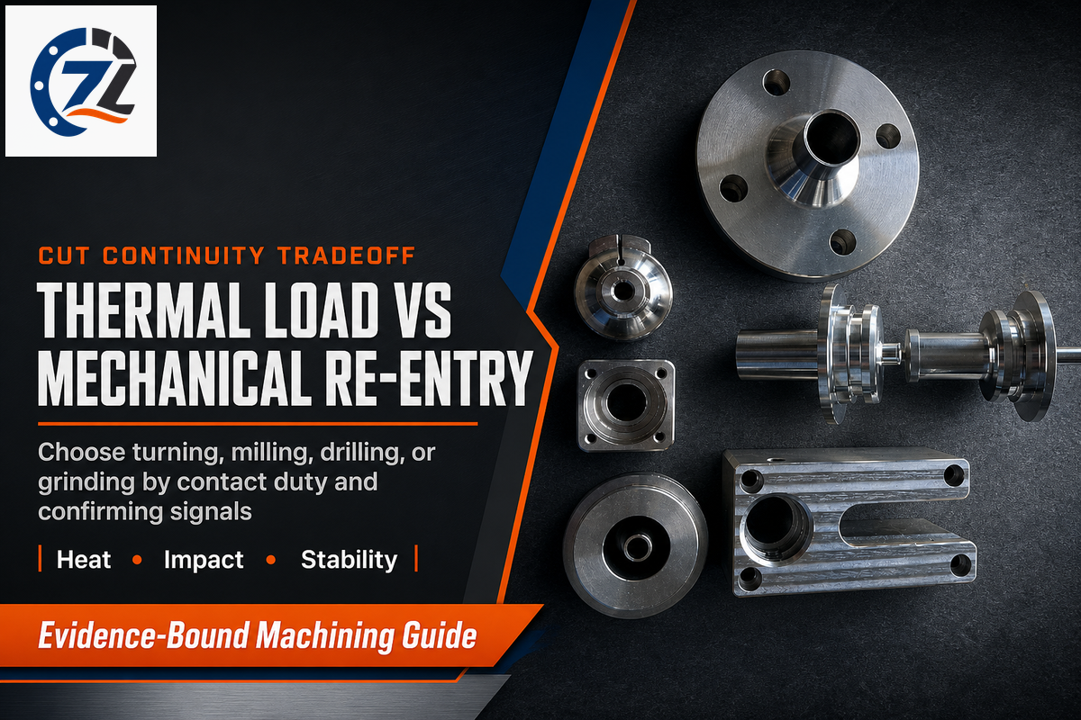
Which operation to choose—continuous turning or interrupted cutting—depends on a tradeoff: thermal load for mechanical re-entry, exit, impact, force, reach, and stability. This interaction map shifts the comparison among Inconel machining processes from slogans to evidence: evaluate machining strategies by contact duty rather than cycle time alone; neither a high-speed label nor a nominal constant chip load replaces observed chip and load signals. Continuous turning may retain heat at the edge, while milling or interrupted drilling adds re-entry load and idle time. Neither condition is automatically better; feature geometry and observed signals determine the safer route.
One source-bound drilling comparison makes the tradeoff visible. After a reported 8,800 mm drilling path in Inconel 718, conventional drilling measured 399 °C at the cutting edge and discontinuous drilling measured 361 °C. The interrupted strategy improved coolant access, but feed force rose; after 10,480 mm, chisel-edge contact area was 55% larger. That’s a 38 °C measured difference, about 9.5% relative to 399 °C, inside one experiment. It isn’t a shop setting or a promise that interruption will extend tool life.
399 °Cconventional edge temperature
361 °Cdiscontinuous edge temperature
8,800 mmtemperature-comparison path
55%larger chisel contact after 10,480 mm
The open-access drilling study supplies the measured comparison; its 38 °C gap remains specific to that test. NIST adds another boundary: when cutting time becomes small relative to idle time, highly interrupted machining can violate assumptions used by conventional regenerative-stability models. Stability charts for one continuity pattern may not transfer to another.
| Cut class | Thermal exposure | Mechanical or re-entry load | First control variable | Confirming signals | Limitations / not suitable for |
|---|---|---|---|---|---|
| Continuous outside turning | Sustained contact | Steady radial and tangential load | Edge state and chip control | Chip, flank wear, size trend | Not a model for cross holes or interrupted skin |
| Facing toward center | Changing surface speed | Changing chip formation | Path and center behavior | Chip change, center finish | One diameter does not represent the full pass |
| Light peripheral milling | Intermittent cooling periods | Repeated entry | Radial engagement and runout | Tooth-to-tooth wear, sound | Not equivalent to full slotting |
| Full-slot milling | Restricted chip and coolant access | High engagement | Chip evacuation | Recutting, load, flute packing | Peripheral data cannot be copied directly |
| Interrupted pocket milling | Idle cooling between contacts | Impact and re-entry | Edge preparation and toolpath | Chipping, notch location, vibration | A patent or supplier test does not rank all tools |
| Cross-hole turning | Repeated hot-cold contact | Edge shock at interruption | Entry geometry and edge strength | Chipping at interruption, burr | Continuous-turning life is not predictive |
| Shallow drilling | Heat near margins and chisel | Thrust and rubbing risk | Margin condition and coolant access | Thrust, chip form, hole size | Does not model deep-hole chip travel |
| Deep-hole drilling | Restricted evacuation and delivery | Bar, guide, and alignment loads | Chip exit and alignment | Torque, thrust, straightness, chips | Shallow-hole settings are insufficient evidence |
| Grinding after treatment | Localized surface heating | Abrasive contact and wheel condition | Wheel state and thermal damage check | Burn, residual stress, size, dust control | Not a substitute for a surface-integrity plan |
5. Select Tool Material, Edge Geometry, and Coating as a System
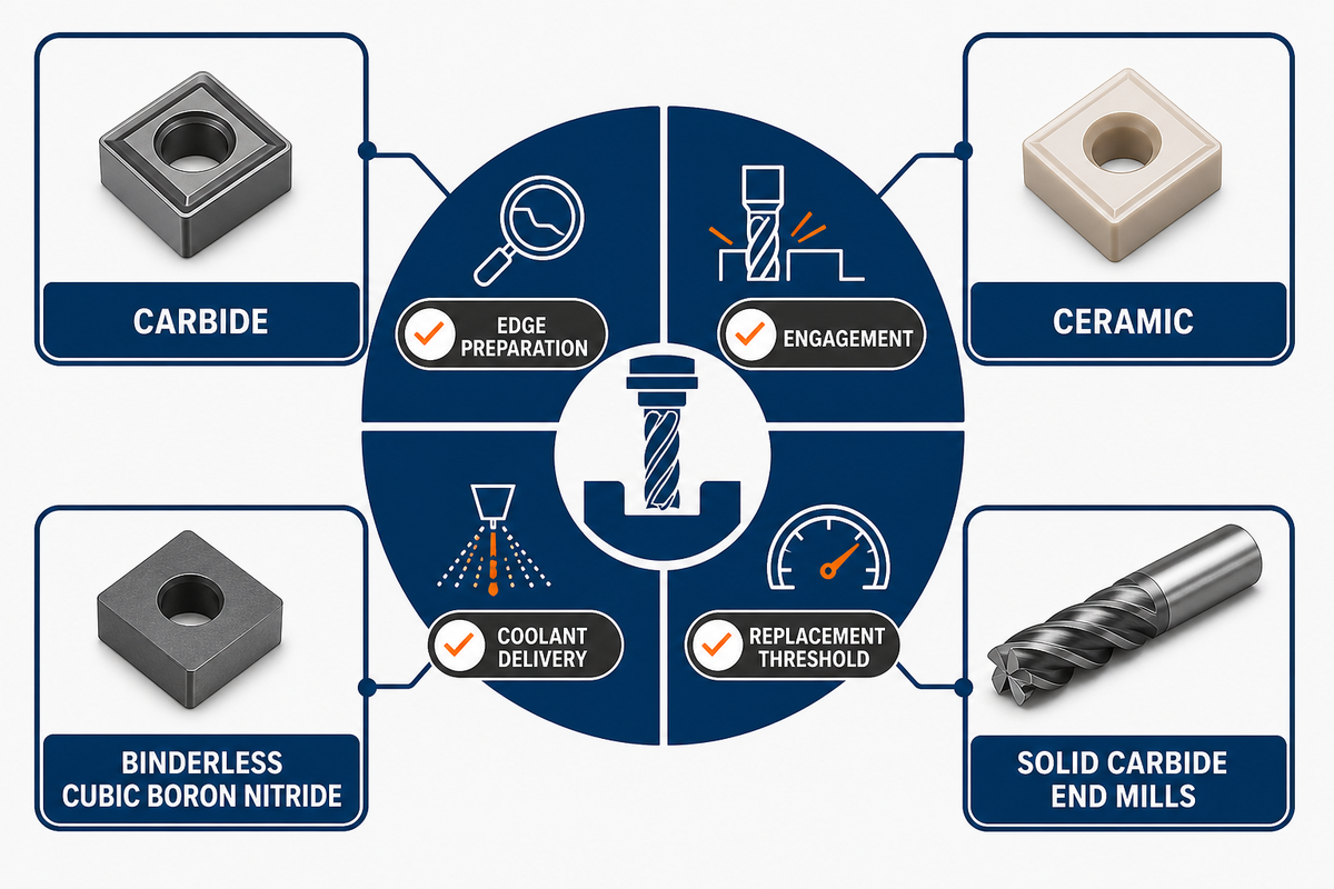
An Inconel cutting tool is a system of substrate, edge preparation, rake and clearance geometry, coating, holder, runout, engagement, coolant delivery, and replacement threshold. Carbide, ceramic, cubic boron nitride, or an aluminum titanium nitride coating label can’t predict success without the operation, material state, continuity, and failure mode.
Sharper cutting edges may reduce rubbing and force, but insufficient edge strength can raise chipping risk under interruption. Rounded or prepared edges may survive longer while changing contact, heat, and the final surface. The reviewed Inconel 718 literature index captures this tradeoff: edge design can improve tool life while harming surface integrity under another condition.
Patents require the same evidence discipline. The public record for US11389879B2 lists Maryam Aramesh as inventor and McMaster University as both the current and original assignee for the ultra-soft coating concept. Its test setup names 50 m/min, 0.1 mm/rev, 0.15 mm depth of cut, 0.3 mm flank wear as the failure threshold, and a 0.4 mm nose radius; those values describe the patent’s test, not a recommendation. The record establishes attribution and a claimed test setup, not universal performance, freedom to operate, or a ranking among turning, milling, drilling, and grinding; even the stated 50 m/min belongs only to that patent test.
- Carbide: specify grade, geometry, coating, edge preparation, and the engagement it must survive.
- Ceramic: evaluate heat strategy, continuity, edge preparation, and predictable replacement; don’t treat “ceramic” as one behavior.
- Binderless cubic boron nitride: treat the 2026 route study as a bounded comparison, not a family-wide recommendation.
- Solid carbide end mills: check flute space, radial engagement, reach, runout, and chip exit before increasing cutting parameters.
Replacement rule: define the edge condition that ends the test before dimensional drift, surface damage, or random fracture defines it for you.
6. Build a Source-Bound Parameter and Coolant Envelope
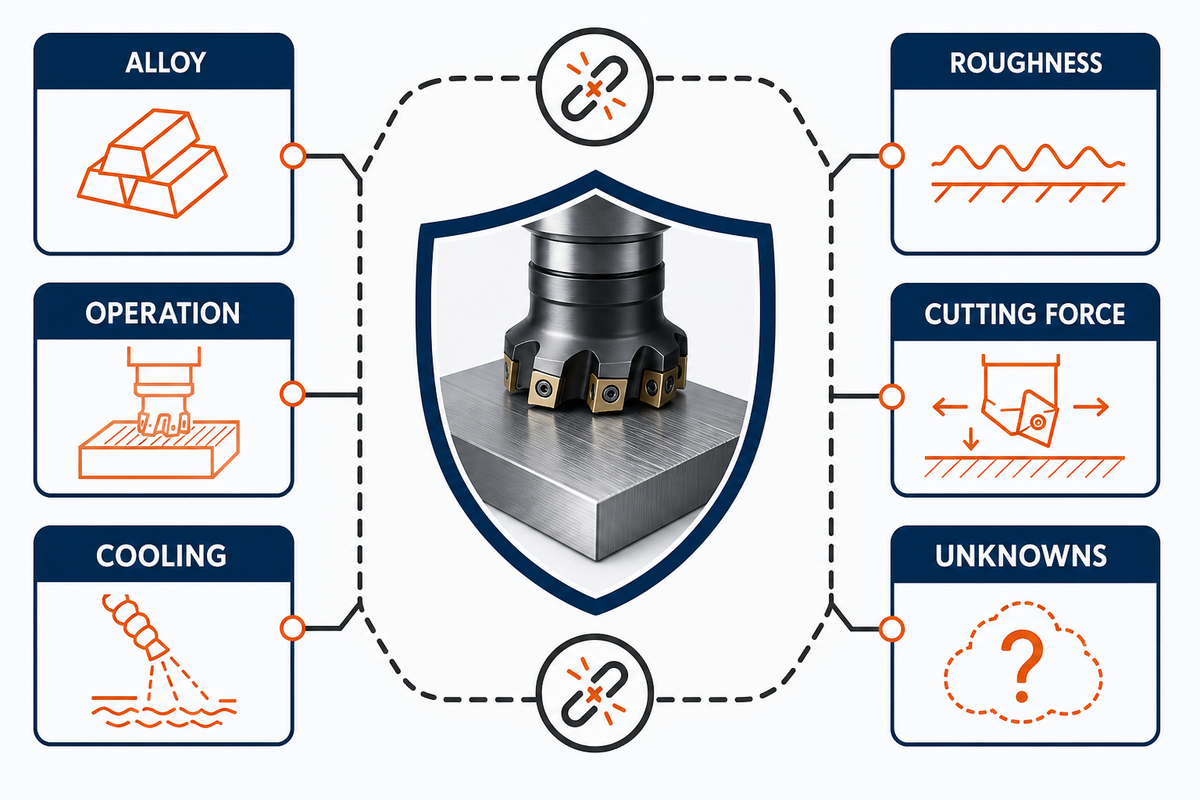
Published speeds and feeds become a candidate starting envelope only when the source exposes alloy, route, condition, operation, tool, edge, engagement, coolant, rigidity, measured outcome, and failure signal. Missing fields stay unknown. A successful value from one face-milling test is not a general Inconel 718 or Inconel 625 recommendation.
A peer-reviewed face-milling study provides a useful worked example precisely because its numbers remain attached to the test. At a reported 100 m/min and 0.15 mm/tooth under its chilled minimum-quantity-lubrication condition, the paper reported 0.221 µm roughness and 163 N cutting force. Its tool-life figures conflict between the abstract or conclusion and the results section, so this guide excludes a tool-life value rather than turning an internally inconsistent report into a shop setting.
| Evidence field | Published test record | Transfer question | Decision |
|---|---|---|---|
| Alloy | Inconel 718 | Is the intended stock the same grade? | No transfer to Inconel 625 by family name |
| Operation | Face milling | Does the intended cut have the same engagement? | No direct transfer to turning or drilling |
| Speed | 100 m/min | Do tool, edge, contact, and cooling match? | Candidate only after all checks |
| Feed | 0.15 mm/tooth | Do runout and actual chip load match? | Do not detach from the cutter |
| Cooling | Chilled minimum-quantity lubrication | Can delivery, temperature, and mist controls be reproduced? | No substitution by label alone |
| Tool-life reporting | Excluded | Do the results and conclusion use the same end-of-life metric? | Paper sections conflict; no transfer value used |
| Roughness | 0.221 µm | Do instrument, location, cutoff, and surface function match? | Not a tolerance or surface-integrity claim |
| Cutting force | 163 N | Do dynamometer and engagement match? | Do not use as a machine-load guarantee |
| Unknowns | Any field not reproduced | Can a controlled trial close the gap? | Keep unknown until measured |
A sound transfer decision doesn’t scale 100 m/min or 0.15 mm/tooth with a universal percentage. It writes the source row beside the intended row, marks mismatches, then designs a conservative controlled trial whose stop signals are defined before cutting. The trial records chip form, edge wear, load, roughness, and size; it changes one input and preserves the rejected result as evidence.
Coolant delivery and workplace aerosol control are separate obligations. One NIOSH evaluation of a CNC department observed airborne metalworking-fluid mist, poor containment at one machine, and inconsistent mist-collector use. That field observation supports a short boundary: reproduce the cutting-fluid condition only under the site’s qualified maintenance and industrial-hygiene controls. It doesn’t supply a universal exposure estimate.
7. Protect Thin Walls, Exit Edges, and the Final Surface
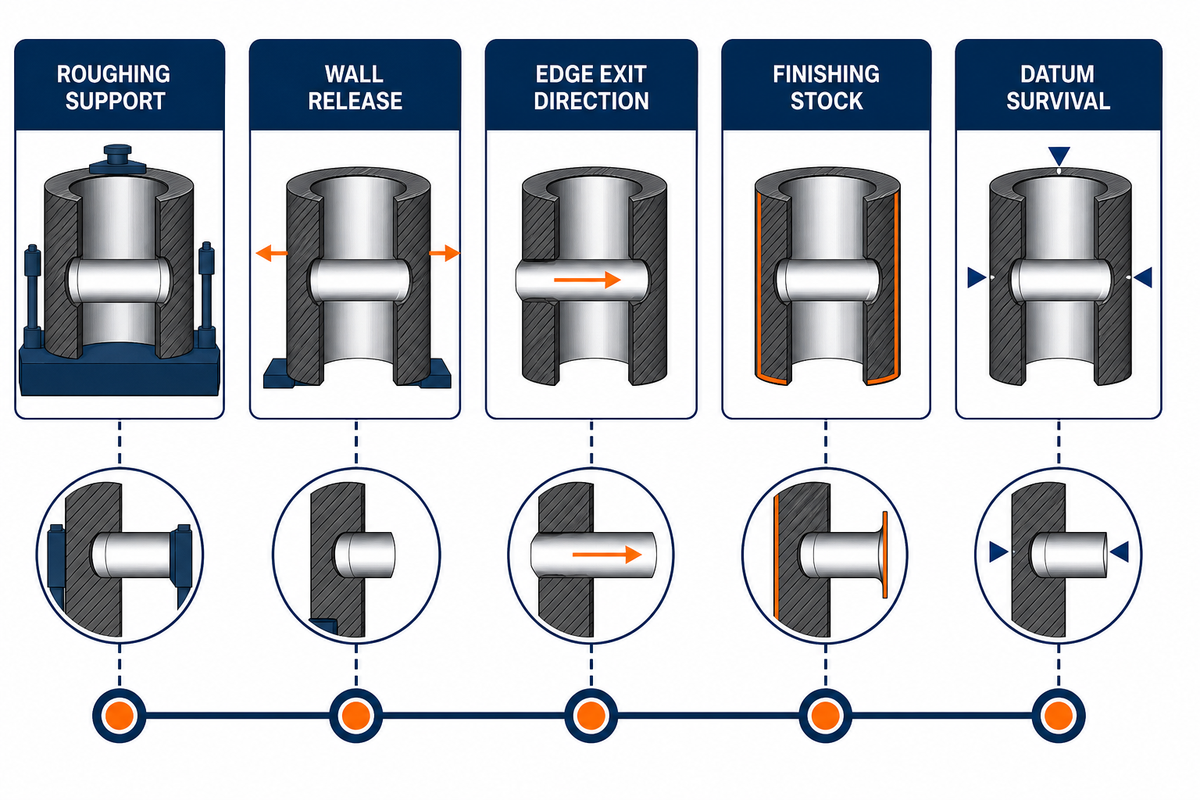
Thin walls, long reach, exit edges, burr-sensitive intersections, and fatigue-critical surfaces change the machining route because stiffness, release, cutting direction, and subsurface condition become acceptance variables. This parameter envelope also means low roughness readings cannot prove that residual stress, work-hardened layers, deformation, burr condition, or final part geometry is acceptable.
Start from the finished feature, then work backward. Define where support is available during roughing, when the wall is released, which direction the cutting edge exits, how much stock remains for finishing, and whether the datum survives a fixture change. Long reach and weak support may turn an apparently modest depth of cut into a deflection or chatter problem.
Picture a thin annular wall with a cross hole near the final edge. Continuous turning provides a stable contact until the tool reaches the interruption; then entry, exit, burr formation, and local wall compliance join the problem. The practical route is to identify which feature is cut first, how the wall is supported at each stage, where the edge exits, and which state governs inspection. Changing speed alone cannot resolve an order-of-operations or restraint error.
Surface finish needs its own acceptance language. State the roughness parameter, direction, measurement location, and instrument conditions; add burr, edge, residual-stress, or subsurface checks only when function, drawing, or quality planning requires them. The 2026 route study found different residual-stress penetration and plastic deformation among its Alloy 718 conditions, which is evidence against treating roughness as the complete surface record.
When not to chase a lower roughness number: Stop if the change worsens wall movement, edge condition, thermal damage, or subsurface risk. The function and drawing decide whether a smoother arithmetic value is actually better.
8. Diagnose Wear, Burrs, Chatter, and Dimensional Drift
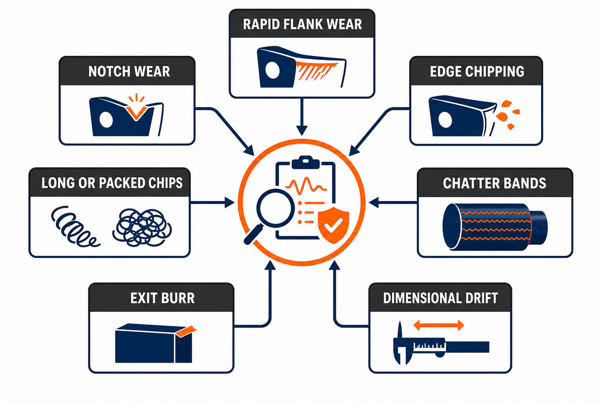
Inconel failure diagnosis should move from one symptom to several plausible mechanisms, then to at least two discriminating observations, one bounded change, and an independent verification. Those observations include flank wear, notch wear, chipping, burrs, chatter, chip changes, and size drift as evidence channels; none identifies one cause by itself.
NIST’s sensor-fusion study found that no individual sensor responded to every monitored machining phenomenon, while a suite covered chip segmentation, chip breakage, and vibration-related events. Another NIST report on intermittent inspection distinguishes process errors visible through on-machine pre-finish inspection from machine-geometry errors requiring independent measurement.
| Symptom | Plausible mechanisms | Observation 1 | Observation 2 | One bounded change | Independent verification | Limitations / not suitable for |
|---|---|---|---|---|---|---|
| Rapid flank wear | Heat, abrasion, unsuitable edge state | Wear image at fixed interval | Load and chip trend | Change one cooling or engagement input | Repeat edge inspection | Do not assume coating failure |
| Notch wear | Depth boundary, hardened layer, oxidation, chip contact | Notch location | Depth and stock history | Shift one engagement boundary | Compare notch location | No universal depth change |
| Edge chipping | Impact, runout, weak edge, chatter | Tooth-by-tooth damage | Entry and vibration record | Change entry path or edge preparation | Inspect all teeth | Do not hide runout with a stronger edge |
| Built-up material | Adhesion, unstable cutting state, edge damage | Edge microscopy | Surface tearing and chip | Change one edge or cutting-state input | Material-transfer check | Deposit is not automatically coating loss |
| Long or packed chips | Chip-break failure, blocked flute, delivery loss | Chip shape and color | Flute or bore inspection | Change one chip-control input | Confirm evacuation | Shorter chip is not proof of good finish |
| Unexpected segmentation | Shear localization, fracture, state change | Segment pitch | Force or vibration waveform | Change one engagement input | Inspect surface and edge | May help evacuation yet harm accuracy |
| Chatter bands | System mode, intermittent stability, reach, runout | Frequency or sound | Tool and fixture response | Change one dynamic input | Independent surface check | A conventional stability lobe may not fit interruption |
| Exit burr | Exit direction, edge wear, weak wall, stock condition | Burr location and orientation | Edge and support state | Change exit path or support | Measure burr and feature | Deburring cannot repair subsurface damage |
| Dimensional drift | Wear, deflection, thermal state, datum, machine geometry | On-machine trend | Independent measurement | Change one verified error source | Recheck datum and geometry | Do not compensate before isolation |
The table is a diagnostic table, not a treatment guide. Each item has been provided with two observations, as there are a number of mechanisms available to explain an individual symptom.
Do
- Photograph or measure the edge at fixed intervals.
- Record chip, load, sound, surface, and size together.
- Change one bounded variable.
- Verify with an independent measurement.
Don’t
- Name one cause from one symptom.
- Change feed, speed, coolant, tool, and fixture together.
- Compensate drift before isolating the error source.
- Turn a successful correction into a family-wide rule.
9. The Parameter Evidence Envelope: What Transfers Between Setups?
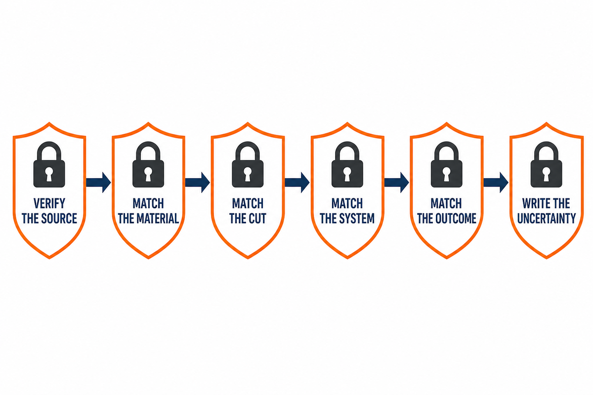
A machining result transfers only as far as its evidence envelope matches the next setup. That symptom-to-evidence method sets the minimum comparison: source quality, alloy, manufacturing route, starting microstructure, condition, product form, operation, tool, engagement, coolant, machine-fixture context, measured outcome, uncertainty, and the current revision of any cited specification.
Score each field as matched, different, or unknown. A difference is not automatically disqualifying, but it must become a test question. An unknown isn’t a safe value and shouldn’t be silently replaced by similarity. This approach is more useful than a market forecast for a stable, low-volume query because it changes an engineering decision today.
- Verify the source: identify whether it’s an official record, peer-reviewed study, trade case, forum observation, or patent claim.
- Match the material: compare grade, route, product form, heat treatment, starting microstructure, and hardness evidence.
- Match the cut: compare operation, tool system, depth of cut, radial engagement, entry, exit, and chip path.
- Match the system: compare holder, runout, machine, fixture, reach, cooling, filtration, and measurement method.
- Match the outcome: compare the tool-life criterion, force channel, roughness method, size state, and surface-integrity requirement.
- Write the uncertainty: mark every unreported field, design one controlled trial, and preserve both successful and rejected results.
Specification currentness belongs in the same envelope. B637-26 replaced the initial assumption that B637-23 was current, while AMS5662P and AMS5663P retain different condition wording. A designation copied without edition, scope, and ordered requirements can make the material brief look precise while leaving the actual condition unresolved.
Keep the measured examples separate: the drilling record contains 399 °C, 361 °C, 38 °C, 9.5%, an 8,800 mm temperature-comparison path, and 55% larger chisel-edge contact after 10,480 mm; the face-milling record retains 100 m/min, 0.15 mm/tooth, 0.221 µm, and 163 N, while excluding the paper’s internally inconsistent tool-life figure. Combining them into one process window would erase two different tools, operations, cooling methods, and measured outcomes.
Key takeaway
A number detached from its material route, cutting system, measured outcome, and uncertainty is not a transferable starting rule.
10. When General Guidance Ends: Drawing-Specific Review

General guidance ends when the decision depends on part geometry, material substitution authority, high-temperature or corrosive service, pressure-code scope, critical surfaces, special-process qualification, inspection coverage, or acceptance criteria. Those questions require the responsible drawing, material, design, quality, code, and manufacturing authorities rather than a generic machining article.
An official ASME and National Board conformity guide shows the boundary. Conformity can span material, design, fabrication, examination, inspection, marking, nonconformance, and data reports. A dimensionally correct machined part doesn’t automatically satisfy those separate controls.
Shop safety also sits outside the parameter chart. Controls for grinding dust, machining aerosol, fluids, guarding, and personal protective equipment must come from the facility’s qualified safety and industrial-hygiene program after it evaluates the actual task. This machining guide doesn’t estimate exposure or prescribe medical action, exposure limits, or protective equipment.
If the question has moved from general evidence to custom Inconel parts, a precision CNC quotation, a specific drawing, material state, operation route, inspection plan, or commercial request, use the custom Inconel part manufacturing scope page. That page owns service capability, quotation, lead-time, and drawing-review intent; this guide doesn’t duplicate those modules.
Frequently Asked Questions
How do you machine Inconel?
Short answer
Machine Inconel by first locking the alloy, manufacturing route, product form, condition, starting microstructure, feature, tool system, engagement, cooling, and acceptance criteria. Choose the operation by continuity, reach, exit, and chip path. Maintain verified chip-forming action, then observe the cutting edge, chip, load, sound, surface, and size together. Change one bounded variable, apply a written stop rule, and confirm the feature with an independent measurement. A family-wide speed-and-feed chart is not a substitute for that controlled trial.
What are standard finishes for machined Inconel?
Short answer
There is no single standard finish for all machined Inconel parts. The drawing and function should identify the roughness parameter, measurement direction and location, edge and burr condition, coating or post-process state, and any residual-stress or subsurface requirement. A low roughness number alone does not prove surface integrity, fatigue performance, sealing behavior, or acceptance in the assembled state.
Is Inconel 718 hard to machine?
Short answer
Inconel 718 is commonly treated as difficult to machine because it retains strength, concentrates heat, work hardens, and can drive adhesion, notch wear, and edge damage. Difficulty still depends on manufacturing route, heat-treatment state, product form, feature, and operation. Wrought, powder-bed-fusion, as-built, hot-isostatically-pressed, solution-treated, and precipitation-treated material should not be assumed equivalent. Even when chemistry matches, starting microstructure can change hardness, chip formation, tool wear, roughness, residual stress, and subsurface deformation. Compare the exact evidence envelope before adopting a process window.
Is Inconel harder to machine than titanium?
Short answer
A family-wide ranking is not reliable. Compare the exact alloys, conditions, feature, operation, tool system, and acceptance requirement instead of transferring a generic machinability score.
Can you 3D print with Inconel?
Short answer
Selected Inconel alloys can be made by additive manufacturing, but printed route, build orientation, porosity, hot isostatic pressing, heat treatment, stock allowance, and starting microstructure affect finishing. The 2026 Alloy 718 comparison found different machining and surface-integrity responses among as-built, post-processed, and wrought conditions. Its small samples and short cutting lengths limit transfer. This guide therefore treats additive route as an evidence-envelope input, not a complete additive process specification or universal tooling recommendation.
What cutting parameters should I use for Inconel 718?
Short answer
No value can be selected from the grade name alone. Use a documented source whose route, condition, operation, tool, engagement, cooling, and failure criterion match, then run a controlled trial with written stop signals.
How We Set the Evidence Boundary
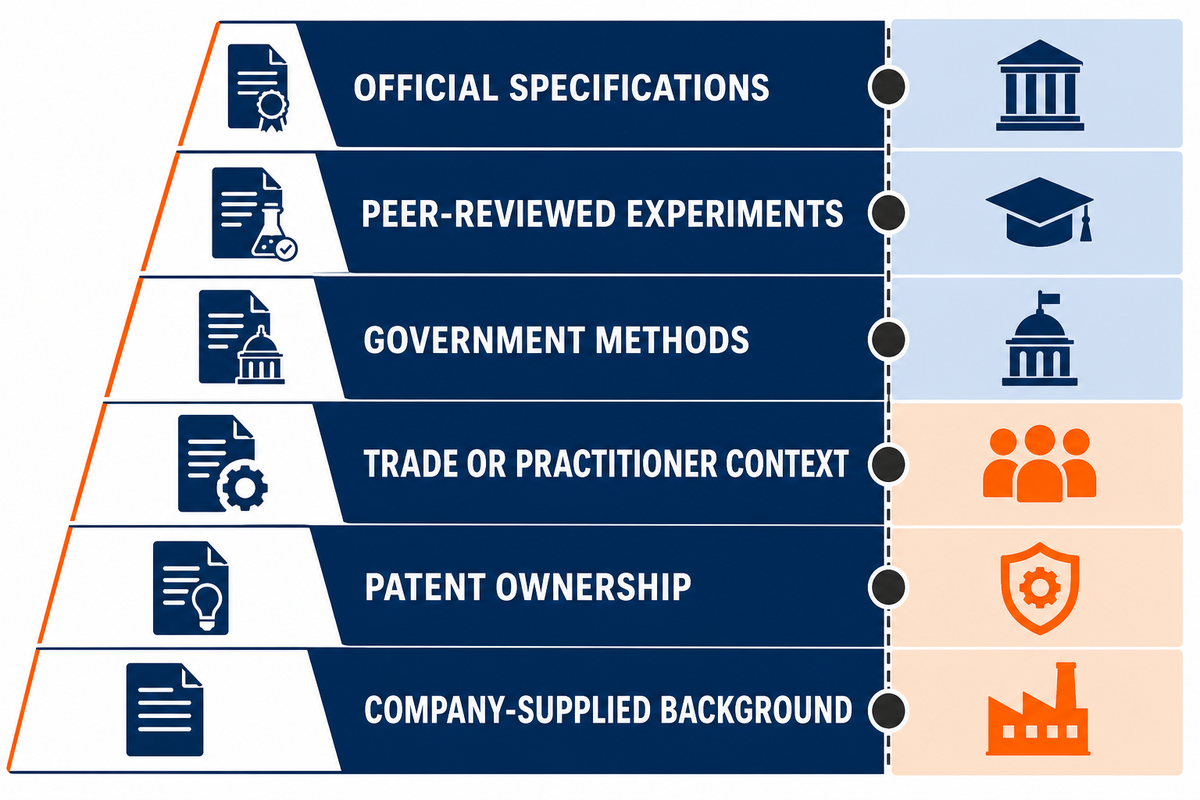
The Inconel CNC machining evidence method separates official specifications, peer-reviewed experiments, government methods, trade or practitioner context, patent ownership, and company-supplied background. According to company-provided information, Shanghai Zhenling Hardware Co., Ltd. has manufactured non-standard metal components since 2006; that profile doesn’t prove an Inconel grade, tolerance, certification scope, process window, or project result. Learn more about Zhenling.
References & Sources
- Tool Wear in Nickel-Based Superalloy Machining Processes, MDPI
- Review of Inconel Machinability Metals, MDPI
- ASTM B637-26 Catalog Record ASTM International
- SAE AMS5662 Alloy 718 Record SAE International
- SAE AMS5663 Alloy 718 Record SAE International
- Machinability and Surface Integrity of Additively Manufactured Alloy 718 The International Journal of Advanced Manufacturing Technology
- Effect of Heat Treatment on Inconel 718 Machinability Journal of Physics: Conference Series
- Chip Formation Mechanism of Inconel 718 Chinese Journal of Mechanical Engineering
- Discontinuous Drilling of Inconel 718 Production Engineering
- Interrupted Machining Stability Theory National Institute of Standards and Technology
- Inconel 718 Research Overview ScienceDirect Topics
- US11389879B2 Patent Record United States patent record hosted by Google Patents
- Chilled-MQL Face Milling of Inconel 718 Jurnal Tribologi
- Health Hazard Evaluation Report 2014-0050-3234 National Institute for Occupational Safety and Health
- Detection of Cutting Phenomena Using Sensor Fusion National Institute of Standards and Technology
- Compensating Errors Detected by Process-Intermittent Inspection National Institute of Standards and Technology
- ASME Conformity Assessment Guide American Society of Mechanical Engineers and National Board
![Shop-Floor Carbon Steel CNC Machining Guide [2026]](https://zhenlingmetal.com/wp-content/uploads/2026/08/carbon-steel-cnc-machining-handbook-r2-featured-150x150.png)