Get in touch with Zhenling Company

Bronze CNC Machining: An Engineering Guide to Alloy, Geometry, and Acceptance

Updated August 2026
Bronze CNC Machining is a precision CNC machining process; a reliable, high-quality result starts by replacing the family word “bronze” with a named alloy, product form, supplied condition, feature set, operation, and acceptance requirement. That identity determines which evidence can transfer. Results from turning one wrought alloy cannot become a milling rule for a cast propeller alloy or an acceptance plan for a porous bearing.
The short answer
- Verify the alloy designation, governing specification, form, condition, and traceability.
- Plan turning, milling, drilling, and boring as different evidence envelopes.
- Match support and measurement to walls, bores, threads, interruptions, and released part state.
- Separate solid bronze from porous or oil-impregnated bearing material.
- Diagnose the observed failure signature before changing a cutting variable.
- Keep workplace, end-use, drawing, and commercial acceptance boundaries distinct.
This guide is an engineering decision framework, not a universal speeds-and-feeds table. Published studies below remain attached to their alloys, tools, operations, and measured outcomes; labels such as “precision bronze” or “better surface” are not transferable acceptance requirements. Its purpose is to help an engineer, buyer, or quality team ask for evidence that makes a bronze part manufacturable and inspectable without turning a case result into a promise.
Engineering note: A published setting is candidate evidence only when alloy, product form, condition, operation, tooling, setup, measured response, and acceptance purpose match the part under review.
Why “Bronze” Is Not a Machining Specification
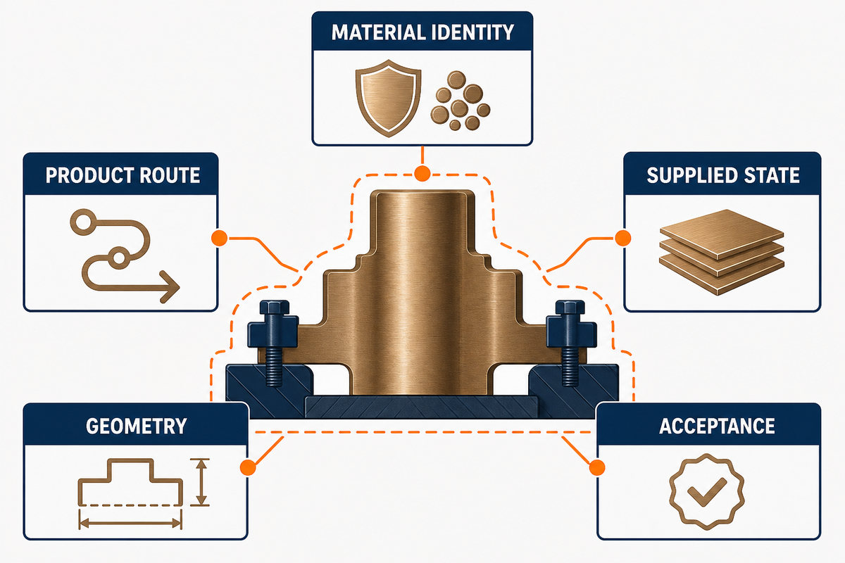
Bronze describes a broad family of copper alloys. It does not, by itself, state chemistry, lead or beryllium status, wrought or cast form, heat history, porosity, lubricant state, mechanical properties, or the specification controlling the supplied stock. Those details can change chip formation, edge loading, burr behavior, surface response, exposure controls, and final acceptance for bronze components.
Start with the exact drawing and material documents. Supplier shorthand, a legacy name, or a generic “bearing bronze” description may help locate a candidate, but it cannot approve substitution. If the drawing, purchase order, certificate, and stock marking disagree, stop at the identity question. Cutting tests cannot resolve a materials-control conflict.
| Bronze Input Identity Card | Record before planning | Decision it controls | Do not substitute |
|---|---|---|---|
| Material identity | Alloy designation, governing specification and edition | Applicable properties, restrictions, and source data | Color, family name, or a nearby trade label |
| Product route | Wrought, continuous-cast, centrifugal-cast, sand-cast, sintered, or other form | Stock variability, porosity boundary, datum and sampling plan | Results from another form |
| Supplied state | Condition, heat/lot, hardness or other required property evidence | Trial envelope and inspection risk | Handbook average without condition |
| Geometry | Walls, bores, threads, interruptions, reach, exit edges, datums | Workholding, operation, toolpath, and measurement state | Generic tolerance class |
| Acceptance | Dimensions, finish, surface condition, cleanliness, function, records, authority | What must be measured, witnessed, or certified | “Machined successfully” as proof of suitability |
This card also protects procurement. Calling stock “machinable” or using a machinability rating can help frame a trial, while a material standard can define a supply scope. Neither automatically proves that the proposed alloy, form, or finished route satisfies a particular drawing; the broader manufacturing services overview is a navigation aid, not substitution approval.
How Named Bronze Alloys and Product Forms Change Machinability
Ask “which bronze, in which form, under which cut?” before asking whether bronze is easy to machine. Leaded bearing bronze, aluminium bronze, phosphor bronze, and porous powder-metallurgy bronze do not form one cutting group. Even two named materials can rank differently when the measured response changes from force to finish, wear, corrosion, or bearing function.
Official Copper Development Association records illustrate the boundary. C36000 is identified as wrought free-cutting leaded brass with a relative machinability rating of 100. C93200 is identified as cast high-leaded tin bronze with a rating of 70 and separate casting routes. Those numbers are reference indices for named alloys. They are not cutting speeds, a service ranking, or permission to replace one material with the other.
One 2025 controlled dry-turning study comparing Brass C26000 with Bronze C51000 reached a defined winner for its force and deformation framework. That is useful counter-evidence to the claim that no comparison can ever have a winner. It still does not show that brass is universally superior for a bearing, wear surface, corrosive environment, electrical part, or another alloy pair. Responsible conclusions keep both truths: a bounded metric can rank candidates, while the family label cannot.
Bronze Product-Route Transfer Boundary
Match the alloy designation, form and condition, operation, tool and edge, engagement, fluid state, setup rigidity, measured response, and acceptance purpose. Mismatches do not make a study useless; they change the result from a candidate setting to mechanism or boundary evidence.
Plan Turning, Milling, Drilling, and Boring as Different Cuts
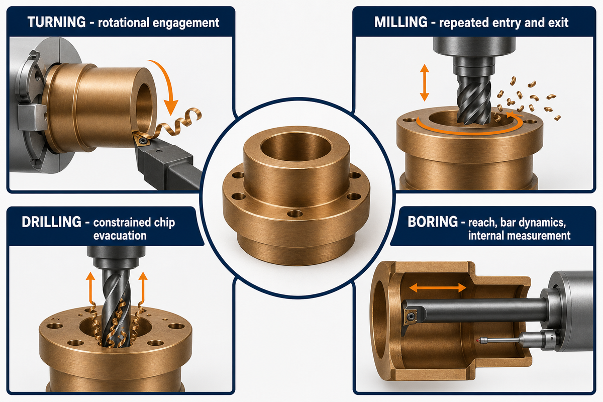
A bronze CNC machining process does not create one repeatable tool-contact event. These machining operations impose different evidence boundaries: CNC turning has continuous or interrupted rotational engagement, CNC milling repeatedly enters and exits, drilling must create and evacuate chips through a constrained path, and boring adds reach, bar dynamics, and an internal measurement problem. Tool geometry, support, chip exit, fluid delivery, and the meaning of a finish result change with the operation.
Two studies show why a universal table is unsafe. The C62300 turning experiment used a 20 mm bar, 800–1,200 rpm, 0.4–0.8 mm depth of cut, and 0.15–0.25 mm/rev feed. The paper reports that a particular tool-construction variant could reduce cutting power by about 30% and machined-surface roughness by about 90–100% within that experiment. Separately, a NIST C95800 milling study reported more than a tenfold material-removal-rate increase against its baseline while tracking force, flank wear, and finish. Neither result is a shop-wide bronze setting.
| Evidence envelope | What was reported | What it can support | What it cannot support |
|---|---|---|---|
| C62300 turning | Bounded bar, speed, feed, depth, and tool comparison | Tool-specific power and roughness response in that test | Universal turning, milling, or different-alloy settings |
| C95800 milling | High-speed milling performance against a study baseline | Proof that a qualified setup can change the productivity envelope | A transferable removal-rate promise |
| First controlled cut | Load, sound, chip, edge, size, temperature state, and surface record | Evidence for one bounded correction | Changing several variables and guessing which one worked |
Metalworking fluid belongs on the same machining process record. OSHA guidance identifies cooling, lubrication, and corrosion-control functions and separates inhalation of mist or aerosol from skin contact. Its health-effects overview makes risk conditional on fluid composition, additives, contaminants, operation, maintenance, hygiene, and exposure conditions. That does not establish a universal fluid recipe or a bronze-specific exposure conclusion.
For planning, record the fluid identity and condition, concentration or maintenance control where applicable, delivery and enclosure state, observed mist or skin-contact route, and post-machining cleanliness requirement. Treat those as process and workplace inputs, not hidden details beneath the alloy name.
Controlled qualification cuts also need a stop rule. Define the expected load band, inspection point, tool-review interval, chip and burr condition, and the characteristic that would trigger engineering review. Preserve the original tool, edge, fluid, fixture, and measurement record when a change is made. Without that baseline, a better-looking surface may conceal faster wear, size drift, unstable chip evacuation, or a fluid-maintenance problem. For repeat work, the useful output is not merely a successful first piece; it is a bounded route that identifies what was held constant, what was adjusted, and what must be checked again when the alloy heat, stock form, tool lot, machine, fixture, or acceptance requirement changes.
Control Thin Walls, Bores, Threads, and Interrupted Features
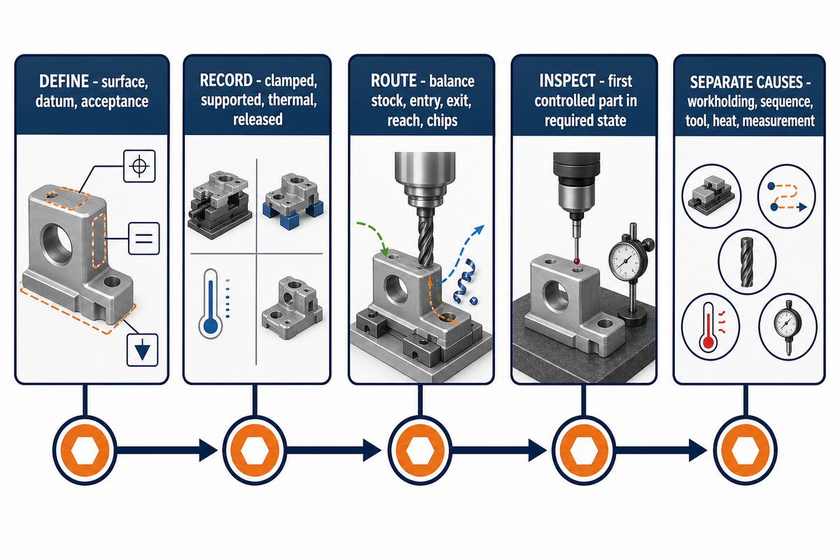
Feature geometry changes the system that produces the measurement. Thin walls may conform while clamped and move after release; bores can show acceptable arithmetic roughness but unsuitable texture or form. Threading combines flank geometry, burr control, entry and exit condition, and gauging method, while interrupted surfaces repeatedly load and unload the edge.
One peer-reviewed thin-wall review identifies stiffness, clamping force, cutting force, temperature, tool geometry, and material history as interacting deformation drivers. Its machining techniques and experiments are in aluminium, so its numerical settings do not transfer to bronze. What transfers is the control architecture: support deliberately, balance stock removal, define the restrained and released measurement states, and remeasure after release when the drawing or process risk requires it.
Direct bronze evidence reinforces that inspection must follow function. One six-page study machined twenty CuSn7Zn4Pb7-C bronze holes using four finishing methods. The method with the best initial finish did not produce the most favorable later wear evolution. One roughness reading therefore cannot choose a bore route when the bore has a functional wear requirement.
Feature control sequence
- Define the functional surface, datum, and acceptance method before toolpath selection.
- Record the clamped, supported, thermal, and released states in which dimensions matter.
- Choose stock-removal balance, entry and exit direction, reach, and chip path around the weakest feature.
- Inspect the first controlled part in the state required by the drawing or quality plan.
- If error appears, separate workholding, sequence, tool condition, thermal state, and measurement state before changing the alloy conclusion.
Separate Solid Bearing Bronze from Porous and Oil-Impregnated Parts
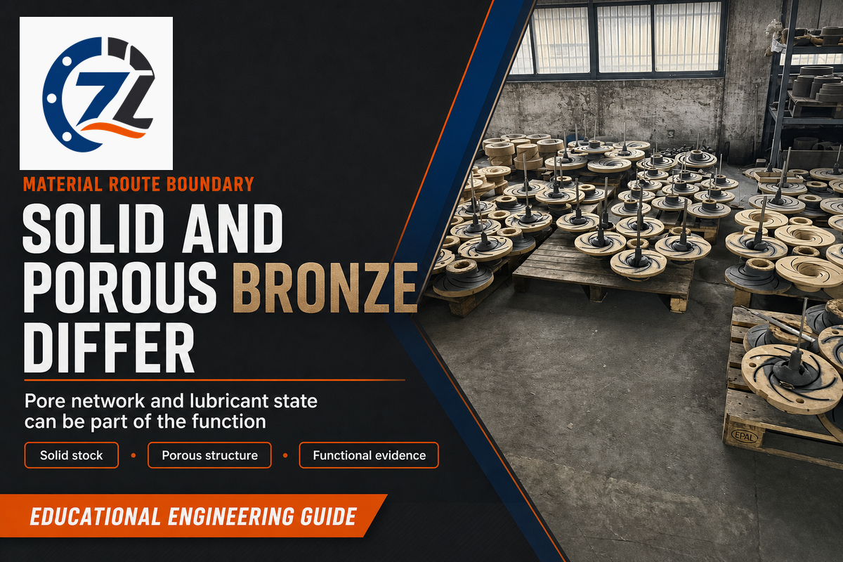
Solid cast or wrought bearing components and porous, sintered, oil-impregnated bearings can share a bronze label while requiring different handling and acceptance. In the porous part, the pore network and lubricant state are part of the function. Cutting that improves a visible surface may smear or close pores, disturb oil behavior, or change an acceptance characteristic that roughness alone cannot represent.
One 2025 porous-bronze fly-cutting study reported pore smearing and collapse with a negative 25-degree rake condition. In one air-bearing-restrictor setup, it reported 4.8% porosity and 0.146 µm roughness. Those values describe one emerging method and one setup; they are not a universal pore or finish target.
ASTM B438-25 shows the broader public acceptance architecture for oil-impregnated powder-metallurgy bronze bearings: grade and type, chemistry, density, minimum oil content, radial crushing strength, dimensions, and optional breaking load are among the named items. That public page is not the purchased standard. It does establish why an attractive surface, visible pores, or one roughness number cannot stand in for all required evidence.
Compare Bronze and Brass Without a One-Word Winner
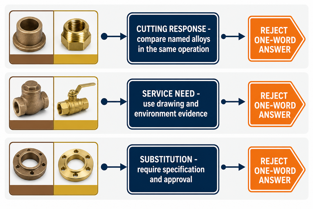
The bronze vs brass question cannot be answered from family names alone. Bronze is not always harder to machine than brass machining stock, and brass is not always the better finished-part choice. A useful comparison names both alloys, separates machining response from service performance, and preserves lead status, form, condition, feature, quantity, inspection, and destination-market requirements.
| Question | Evidence needed | Unsafe shortcut |
|---|---|---|
| Which material cuts with lower force in this operation? | Named alloys, condition, tool, operation, engagement, and measured force | “Brass is easier” without an envelope |
| Which meets the service need? | Drawing properties, environment, wear/corrosion/load basis, governing authority | Using machinability as a service ranking |
| Can one replace the other? | Specification, form, certificate, functional review, and approval | Substitution from color, name, or relative rating |
This approach permits a clear answer when the evidence supports one. It also prevents the answer from expanding beyond the metric that was actually measured. Procurement can then compare cost and availability only after technical candidates share an approved requirement basis.
Inspect Dimensions, Surface Condition, and Functional Evidence
Inspection should answer the drawing’s question, not simply report what is easiest to measure. Dimensions, form, orientation, runout, threads, burrs, arithmetic roughness, texture, pore condition, cleanliness, and functional tests are different evidence objects. Their relevance depends on the surface and service risk.
Build an acceptance map before production: characteristic, datum, method, instrument, restraint state, temperature state, sampling point, frequency, record, and responsible authority. If a wall moves after release, record both process state and acceptance state. If a bore’s wear function matters, do not treat a roughness value as a complete proxy. If porous material is involved, preserve its specification-led evidence.
Visual defects need the same separation. Bright surfaces can still have form error, smeared pores, embedded material, burrs, or an unacceptable texture. Conversely, a visible cutting pattern does not automatically fail a part unless the drawing, specification, or validated function defines it as unacceptable.
Internal casting integrity is another evidence object. The public scope of ASTM E310-21(2026) separates tin-bronze radiographic indications such as gas porosity, sand inclusions, shrinkage, hot tears, inserts, and chaplets, while leaving minimum acceptability to purchaser-supplier agreement. Dimensions, chemistry, arithmetic roughness, and external surface review cannot silently replace the examination method and acceptance level required by the drawing or contract.
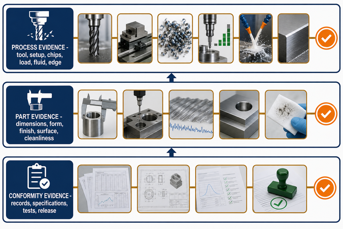
Three evidence levels
Process evidence: tool, setup, chips, load, fluid, edge condition, and controlled adjustments.
Part evidence: dimensions, form, finish, surface condition, internal-integrity examination where required, cleanliness, and functional tests.
Conformity evidence: material records, approved specifications, authority-defined tests, certification, and release responsibility.
Use the Bronze Failure Signature Atlas to Troubleshoot the Cut
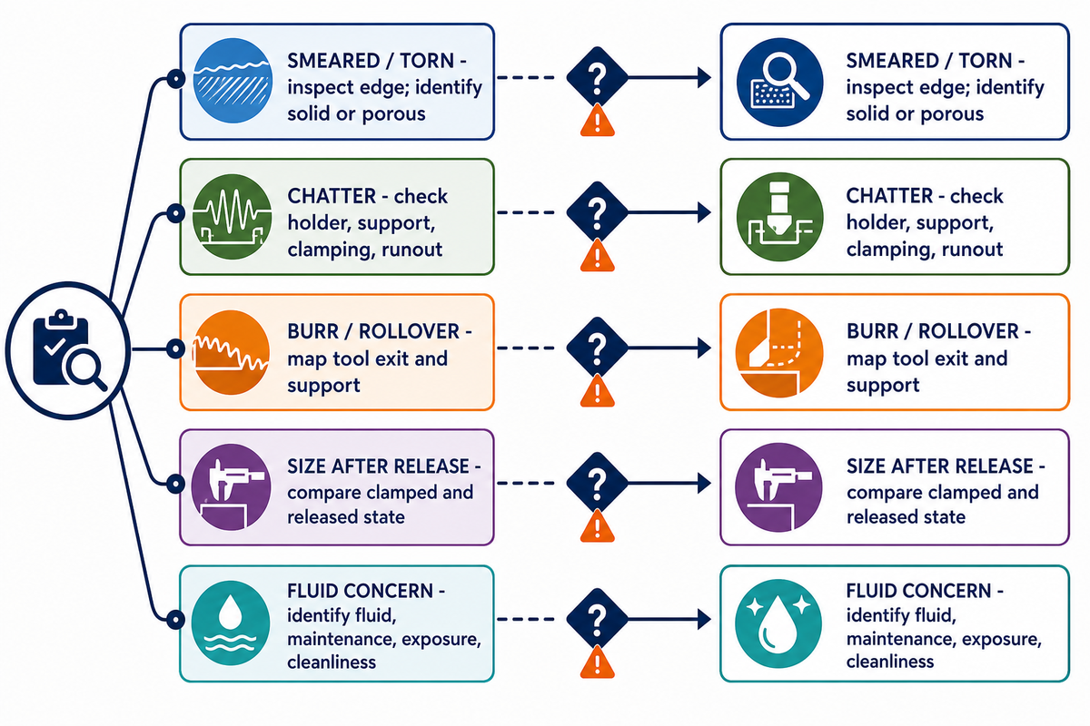
Each symptom is a starting signal, not a diagnosis. Machinists should preserve the baseline, choose a discriminating check, change one bounded variable, and verify the result. This is more defensible than changing speed, feed, depth, coolant, tool, and clamping together.
| Bronze Failure Signature Atlas | Plausible mechanisms | Discriminating first check | Bounded response | Verification |
|---|---|---|---|---|
| Smeared or torn surface | Edge deposition, dull or unsuitable geometry, rubbing, pore smearing | Inspect edge and identify solid versus porous material | Correct one edge or engagement variable within qualified data | Surface, edge photo, dimension, pore condition if relevant |
| Chatter bands | Low dynamic stiffness, reach, support loss, unstable engagement | Check holder, support, clamping, runout, and repeat spacing | Shorten or support the system, then adjust one engagement variable | Sound/load record, finish, and released geometry |
| Burr or exit-edge rollover | Unsupported exit, edge wear, path direction, insufficient cutting action | Map burr location to tool exit and support | Change support or exit strategy before adding deburring | Edge profile and dimensional effect |
| Size changes after release | Clamp distortion, stock imbalance, thermal state, residual stress | Measure clamped and released state at a defined temperature | Rebalance sequence or support; avoid cutting to the clamped error | Repeated released-state measurement |
| Fluid residue, odor, mist, or skin-contact concern | Fluid condition, contamination, delivery, enclosure, hygiene, cleaning mismatch | Identify fluid and review maintenance, exposure route, and cleanliness criterion | Follow the responsible workplace and process-control route | Fluid record, control check, and cleaned-part acceptance |
This atlas deliberately uses “plausible mechanisms.” Similar marks can come from different causes, and more than one mechanism can be active. Verification should show improvement in the target signal without damaging another requirement such as size, pore condition, edge integrity, cleanliness, or tool life.
Where General Guidance Ends: Drawing and Acceptance Boundaries

Machining feasibility does not establish workplace compliance, material substitution, potable-water suitability, bearing acceptance, or service conformity. These decisions may share evidence, but they have different owners and controlling documents. The responsible owner must confirm both applicability and the final acceptance path.
| Bronze Acceptance Boundary Matrix | Trigger | Evidence needed | What machining evidence cannot prove | Handoff |
|---|---|---|---|---|
| Alloy identity | Material callout or substitution request | Specification, edition, form, condition, certificate, approval | Equivalence or service suitability | Engineering and materials control |
| Cast internal integrity | Tin-bronze casting with an internal-discontinuity requirement | Drawing or contract-defined examination method, category, and acceptance level | Internal acceptability from size, chemistry, roughness, or appearance | Purchaser, supplier, qualified inspection personnel, and quality authority |
| Beryllium-bearing material | Verified composition within the applicable occupational scope | Applicable exposure assessment and controls | Compliance from clean chips or a finished surface | Responsible workplace safety authority |
| Lead-bearing material | Composition plus cutting, grinding, or another exposure pathway | Applicability and exposure assessment | A universal exposure level | Responsible workplace safety authority |
| Copper dust, mist, or fine powder | Machining, finishing, handling, or cleanup creates process-specific particulate | Particle-state and exposure assessment plus the applicable ignition and housekeeping review | Safety from the absence of lead or beryllium, or from bulk-metal behavior | Responsible workplace safety authority |
| United States potable-water use | Covered pipe, fitting, fixture, faucet, solder, or flux | Scope, wetted-surface calculation, exemptions, and required conformity route | Acceptability from alloy name alone | Applicable United States authority and certification path |
| European potable-water use | Material or product contacting water intended for human consumption | Destination-specific positive-list and conformity review; Decision (EU) 2024/367 is stated to apply from 31 December 2026 | Global acceptance from a United States threshold | Controlling European and destination-market authority |
| Porous bearing | Sintered or oil-impregnated function | Applicable material, density, oil, strength, dimension, and functional evidence | Acceptance from roughness or visible pores | Drawing, specification, and quality plan |
| Commercial execution | Drawing, quantity, delivery, or quotation decision | Drawing package and supplier-specific review | Price, lead time, capacity, or result from this guide | Commercial solution owner |
8-Row Source-Bounded Evidence Matrix
Use this register to identify where a number came from before it is repeated. Rows are intentionally incompatible with one another: machining-test inputs, measured outcomes, workplace limits, and end-use thresholds answer different questions.
| Evidence type | Source-bounded values | Allowed use | Transfer stop |
|---|---|---|---|
| C62300 workpiece | 20 mm bar | Identify the turning experiment | Not another alloy, form, or diameter |
| C62300 spindle range | 800 rpm to 1,200 rpm | Describe tested endpoints | Not a recommended machine setting |
| C62300 cut inputs | 0.4 mm to 0.8 mm depth; 0.15 mm/rev to 0.25 mm/rev feed | Keep outcomes attached to test limits | Not milling or different-tool data |
| C62300 outcome | Paper-reported reductions of about 30% in cutting power and about 90% to 100% in surface roughness for one tool variant | Compare variants inside that study | Not a supplier or production promise |
| Porous-bronze setup | Negative 25° rake; 4.8% porosity; 0.146 μm roughness in one setup | Identify a pore-smearing counterexample | Not a universal pore or finish target |
| OSHA beryllium | 0.1 μg/m³ action level; 0.2 μg/m³ over 8 hours; 2.0 μg/m³ short-term limit | Flag the applicable occupational route | Not proof of shop exposure |
| OSHA lead | 30 μg/m³ action level; 50 μg/m³ over 8 hours | Flag composition and exposure assessment | Not a universal bronze result |
| United States potable-water scope | 0.25% weighted wetted-surface threshold; 0.2% for solder and flux | Identify the covered end-use question | Not a global alloy limit |
For United States workplaces, OSHA’s current beryllium standard lists an eight-hour permissible exposure limit of 0.2 µg/m³, an action level of 0.1 µg/m³, and a short-term exposure limit of 2.0 µg/m³. Its lead standard lists an eight-hour action level of 30 µg/m³ and a permissible exposure limit of 50 µg/m³. These numbers belong to their legal scopes; they do not show that every bronze operation reaches or exceeds a limit.
Copper particulate remains a separate question even when lead and beryllium are absent. The NIOSH Pocket Guide entry for copper dusts and mists treats that exposure state separately and distinguishes noncombustible bulk copper from powdered material that may ignite. It does not prove that a specific bronze process creates a given concentration; it requires the process, particle state, exposure route, and responsible controls to be assessed rather than inferred from alloy chemistry alone.
For covered United States potable-water products, the Environmental Protection Agency explains a 0.25% weighted average lead content across wetted surfaces and separate treatment of solder and flux, along with statutory scope and exemptions. That is a United States end-use boundary, not a global bronze chemistry rule.
For the European route, Commission Implementing Decision (EU) 2024/367 establishes positive lists for drinking-water-contact materials, including metallic compositions in Annex II, and states that it applies from 31 December 2026. On this article’s 5 August 2026 research date, that application date was still in the future. Destination and product scope must be checked against the controlling text rather than inferred from this summary.
Minimum package for a drawing-level review
- Drawing revision, three-dimensional model where applicable, quantity, and required delivery stage.
- Exact alloy designation, governing specification and edition, product form, supplied condition, and required material records.
- Critical characteristics, datum scheme, threads, edges, surface requirements, cleanliness, and any released-state measurement rule.
- Service environment and the authority that owns material, workplace, potable-water, pressure, marine, wear, or other regulated acceptance.
- Required inspection method, sampling level, internal-integrity category where applicable, first-article or batch records, and any witness or certification obligation.
- Known restrictions on fluid, particulate, residue, cleaning, deburring, marking, packaging, housekeeping, or traceability.
Missing information should remain marked as unknown. Manufacturing review can identify questions and propose a qualification route, but it should not silently fill a regulatory or functional gap with a familiar alloy, tolerance, or process assumption.
Translate search vocabulary into evidence
Phrases such as precision bronze machining, custom bronze, CNC machining services, bronze materials, aluminum bronze’s machining characteristics, bronze CNC machining service, feed rate, machining capabilities, advanced machining techniques, high-precision, material properties, precision bronze components, and successful bronze machining are request labels until the drawing fixes the evidence envelope.
The same rule applies to standard bronze, machining approaches, precision parts, advanced CNC, bronze grades, CNC-machined bronze, rough machining, different bronze, machining applications, proper machining techniques, tight tolerances in bronze, bead blasting, bronze bushings, and different CNC machining routes. Each phrase still needs alloy-and-form context.
Likewise, machining materials, custom bronze parts, ultra-precision bronze, CNC machining facility, common bronze, various bronze, machining industry, machining tolerances, bronze stock, machining requirements, and CNC operations describe search or procurement categories, not verified performance.
Terms such as machining services, aerospace, industrial applications, tight tolerances, corrosion resistance, wear resistance, bushing, and machined bronze describe possible inquiry context. Their presence is not evidence that a particular alloy, process, supplier, or finished part meets any of those requirements.
When the discussion moves from education to a real part, the neutral next step is a drawing-specific bronze machining review. That handoff is where supplier-specific questions belong; this guide does not state Zhenling bronze production results, tolerances, certifications, capacity, prices, lead times, or customer outcomes.
Bronze CNC Machining Questions
Is bronze easy to CNC machine?
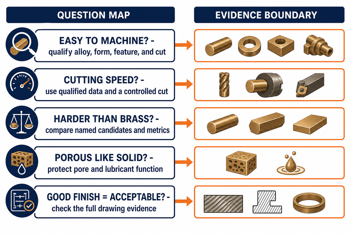
Some named bronze alloys and conditions can machine productively, while others create higher force, edge deposition, wear, burr, porosity, or workholding challenges. “Easy” is meaningful only after the alloy, form, condition, feature, operation, tool system, and acceptance requirement are known. Stable external turning on solid bar may need a different route from a deep bore, interrupted blade surface, slender wall, or oil-impregnated bearing. In practice, qualify the exact material and feature, observe a controlled first cut, and verify the part in its required measurement state.
What cutting speed should be used for bronze?
There is no defensible family-wide speed. Start with qualified data for the exact named alloy, condition, operation, tool and coating, engagement, fluid state, and machine setup. Run a controlled cut, record the response, and change one bounded variable at a time. Treat any published value as a trial boundary until chip behavior, tool wear, temperature, finish, dimensional stability, and burr condition have been checked on the actual part.
Is bronze harder to machine than brass?
Not as a universal rule. One named brass may rank better for a machining metric, yet one named bronze may be selected for a different service requirement. Compare specific alloys, product forms, operations, measured responses, and functional priorities instead of comparing family names. Useful comparisons put drawing-specific candidates under the same cutting test and acceptance method rather than treating broad labels as equivalent materials.
Can porous bronze be finished like solid bronze?
Do not assume so. Porous or oil-impregnated parts have a pore and lubricant function that cutting can change. Applicable material specifications, drawings, and quality plans should define which dimensions, density, oil, strength, surface, and functional evidence are required.
Does a good surface finish prove a bronze part is acceptable?
No. Arithmetic roughness is one measurement. Form, texture, burrs, pore condition, cleanliness, material identity, strength, fit, functional tests, and conformity records may also control acceptance. Use the drawing and applicable specification to decide which evidence matters.
References & Sources
The article uses the following government, academic, association, standards, and established industry sources. Study results remain limited to their published materials and setups.
- NIST — Tool Wear and Surface Finish in High-Speed Milling of Aluminum Bronze.
- Peer-reviewed C62300 turning study.
- 2025 C26000/C51000 dry-turning comparison.
- CuSn7Zn4Pb7-C bore-finishing and wear study.
- 2025 porous-bronze fly-cutting study.
- Copper Development Association C36000 record and C93200 record.
- ASTM B438-25 public scope.
- OSHA 29 CFR 1910.1024 — Beryllium and 29 CFR 1910.1025 — Lead.
- OSHA Metalworking Fluids Safety and Health Best Practices Manual and Health Effects.
- NIOSH — Risk Factors and Work Activities for Lead.
- NIOSH Pocket Guide — Copper (dusts and mists, as Cu).
- United States Environmental Protection Agency — Safe Drinking Water Act lead-free scope.
- ASTM E310-21(2026) public scope — Standard Reference Radiographs for Tin Bronze Castings.
- EUR-Lex — Commission Implementing Decision (EU) 2024/367 and the European Commission drinking-water overview.
Evidence note: this article found no authoritative bronze-specific year-over-year market driver and therefore does not include a market-growth forecast. It also does not claim client-specific bronze results or conformity.
![Shop-Floor Carbon Steel CNC Machining Guide [2026]](https://zhenlingmetal.com/wp-content/uploads/2026/08/carbon-steel-cnc-machining-handbook-r2-featured-150x150.png)



ZHENLING / MADE-TO-PRINT MANUFACTURING
From Engineering Question to RFQ-Ready Drawing
Zhenling supports custom flanges, valve bodies, rolls, bent pipe, and profiled machined parts for industrial buyers. Our engineers review the drawing, material condition, tolerance stack, quantity, and inspection requirements before the machining route is quoted.
START WITHDrawing · Sample · Critical dimensions
DEFINEMaterial · Quantity · Tolerance · Certification
DRAWING / MATERIAL / TOLERANCE
Prepare Your Part Brief
- PART INPUT
- 2D/3D drawing or sample
- PROCESS REVIEW
- Machining · forming · welding · inspection
- RESPONSE ROUTE
- Submit the website inquiry form
We use your details to review and respond to the enquiry. See our Privacy Policy.