Get in touch with Zhenling Company

Updated August 2026
Titanium CNC machining refers to the controlled turning, milling, drilling, or finishing of titanium stock into a defined part and accepted evidence state. It isn’t governed by a single speed-and-feed chart. Reliability comes from connecting the exact material condition, cutting engagement, edge condition, coolant access, chip flow, part support and inspection plan. Vary any one of those variables and an acceptable cut may compromise tool life, surface integrity or the released geometry.
This guide explains how to frame those decisions before a parameter becomes a production rule. Commercial capability and quotation review belong on the solution page; this article is an educational process-control reference.
Why Titanium Moves Heat and Load Into the Cutting Edge
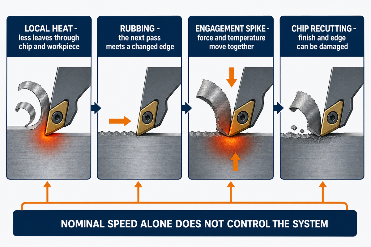
Titanium presents unique challenges because the cutting zone can retain heat while the tool repeatedly meets a strong, elastic workpiece. Low thermal conductivity means less heat leaves through the chip and workpiece than a machinist may expect from metals like aluminum. Local rubbing, an unstable edge, or poor chip evacuation can therefore accelerate tool wear before the whole titanium part feels hot.
This guide does not publish a universal recipe or claim that Zhenling has aerospace, defense, medical, dental, or implant approval.
That mechanism also explains why “titanium is difficult” is too vague to guide a machining project. Titanium’s strength, ductility, chemical reactivity at elevated cutting temperatures, and tendency to work harden can interact with tool geometry and engagement. High tensile strength or a high strength-to-weight ratio describes material performance; it does not reveal whether a mill, turning center, drill, carbide grade, holder, or coolant route is suitable for the released feature.
Heat buildup is usually local. If the edge dwells or rubs, the next pass meets a changed surface and a changed tool. If engagement spikes at a corner, force and temperature can change together. If a chip is recut, it can damage the surface finish and edge without any change in programmed feet per minute or meters per minute. Stable titanium machining therefore depends on the system around the nominal cutting speed.
Published experiments illustrate the importance of a complete envelope. One finish-turning study used 120 m/min, 0.25 mm depth of cut, 0.1 mm/rev, and minimum-quantity lubrication at 30 ml/h and 0.7 MPa. Tool life was compared by removed-material volume until each insert reached its stated wear criterion; the sharp uncoated insert lasted more than 3 times coated insert A and more than 5 times coated insert B in that setup. Those numbers describe one study, not a general prescription. Review the study conditions before using its result.
Titanium Grade, Condition, Manufacturing Route, and Microstructure: Why the Label Is Not a Recipe
That thermal-and-load picture is incomplete without the material definition: a titanium grade is one part of the definition and does not, by itself, represent the cutting condition. Certificates, form, heat treatment, method of manufacture, and microstructure can affect how the titanium alloy responds at the cutting edge. Labels such as “Grade 5”, “commercially pure titanium”, and “wrought titanium” are useful starting identifiers, but they cannot release a job by themselves.
Current material documentation still has product-form boundaries. For example, ASTM B348/B348M-25 covers titanium and titanium-alloy bars and billets, while ASTM B265-25 covers annealed strip, sheet, and plate. A callout for one form does not silently establish another form’s condition, certification, or process history.
Working with titanium starts by asking whether the specified grade is the right material for the application. Titanium Grade 5 is one frequently discussed alloy, but its name alone does not establish the product form, heat treatment, mechanical properties, or acceptance plan. If titanium is not yet fixed, use the broader materials library and CNC material selection guide to separate material screening from the machining evidence reviewed here.
Some applications requiring low mass and corrosion resistance may favor titanium; titanium is also discussed for its strength and corrosion resistance across a range of applications. Those general reasons do not prove that a finished part will be resistant to corrosion in its actual environment, hold tight tolerances, or carry the same evidence burden across prototypes and production parts.
| Identifier | Question to resolve | Why it matters at the cut | Transfer limit |
|---|---|---|---|
| Grade and specification | Which current designation and substitution rule control? | Narrows chemistry and required material evidence | Does not define a universal cutting parameter |
| Product form and condition | Bar, billet, sheet, plate, forging, casting, or other form? | Changes stock history, allowance, and support questions | One form’s document does not qualify another |
| Manufacturing route | Wrought, additively manufactured, or another declared route? | May introduce anisotropy, porosity, or route-specific thermal history | Grade equivalence does not prove route equivalence |
| Microstructure and post-process | Which heat treatment and microstructural state apply? | Can change force, wear, and surface response | A laboratory result stays inside its test envelope |
Microstructure is not a theoretical footnote. A micromilling paper compared 4 Ti-6Al-4V microstructures with a 200 µm, two-flute tool and found lower force and wear for a fully lamellar condition in that specific experiment. It does not prove that fully lamellar stock is always easier to machine at conventional scale. Likewise, a review of additively manufactured and wrought titanium discusses anisotropy, porosity, thermal history, and post-processing as route-dependent influences. Use those findings to ask for material history, not to invent a cross-route parameter.
Evidence boundary: Cited micromilling work used a 200 µm cutter, while another cited milling experiment used a 20 mm tool and the finish-turning study used a 0.25 mm depth of cut with 0.1 mm/rev feed. That face-milling study’s 6 mm stock thickness is likewise a test condition, not a thin-wall acceptance limit. These dimensions describe three different test envelopes; they cannot be blended into one recipe.
| Published source envelope | Reported condition | What the value supports | Transfer limit |
|---|---|---|---|
| Finish turning | 120 m/min cutting speed | Identifies the reported comparison point | Not a universal titanium speed |
| Finish turning | 0.25 mm depth of cut | Bounds the reported engagement | Does not define a milling depth |
| Finish turning | 0.1 mm/rev feed | States the reported feed basis | Cannot be converted into feed per tooth without a new setup |
| Finish-turning lubrication | 30 ml/h at 0.7 MPa | Identifies the reported delivery envelope | Not a general fluid recipe |
| Micromilling | 200 µm two-flute cutter | Bounds the reported microstructure comparison | Does not establish conventional-scale behavior |
| Face-milling workpiece | 100 × 100 × 6 mm Ti-6Al-4V | Identifies the reported workpiece envelope | Does not represent every wall or pocket |
| Face-milling tool | 20 mm, four-flute carbide tool | Identifies the reported tool scale | Does not establish a universal flute count |
| Face-milling lubrication | 40 ml/h at 0.7 MPa | Identifies the second delivery envelope | Cannot be blended with the turning result |
Application labels require the same restraint. Designers may use titanium instead of steel or aluminum when a defined combination of mass, strength, and corrosion behavior supports the design. Titanium may also be selected for excellent corrosion resistance or high corrosion resistance in a defined environment, or for properties valued in aerospace and medical and dental contexts. Terms such as corrosion resistance, biocompatibility, implant, and extreme temperatures do not prove that a particular supplier, material lot, or machined titanium part is qualified for a regulated use.
The Titanium Cut Stability Envelope
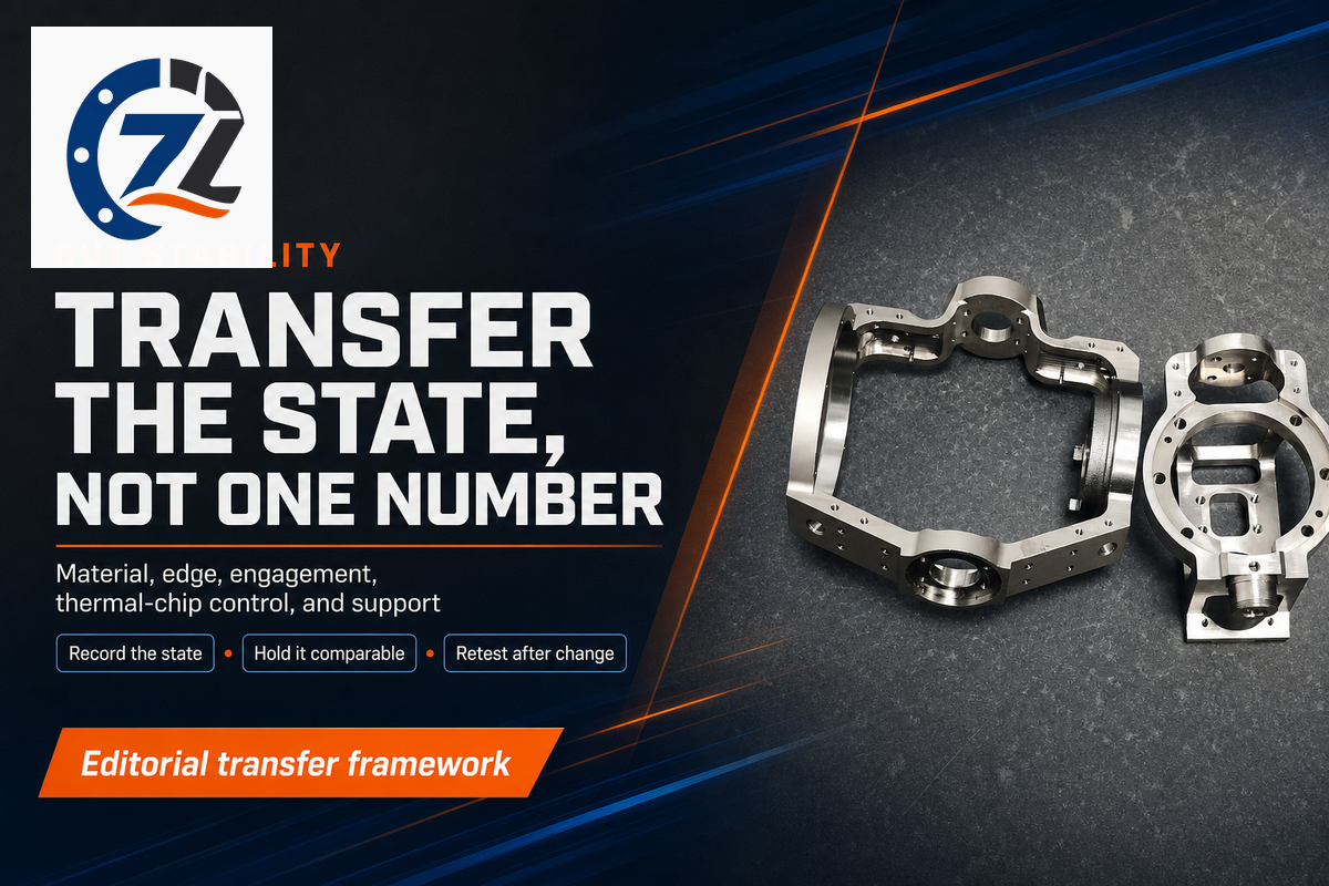
The Titanium Cut Stability Envelope records material state, edge state, engagement, thermal-chip control, and support. A cutting condition is reusable only while those states remain bounded. The envelope tests whether a result can transfer between comparable cuts; it does not screen drawing completeness, qualify a supplier, or replace a material specification.
| Cut state | Record | Warning signal | Next bounded check |
|---|---|---|---|
| Material state | Grade, lot, form, route, heat treatment | A new lot or route behaves differently | Reconfirm certificate and baseline coupon |
| Edge state | Tool, coating, geometry, run time, wear location | Force, burr, color, or finish trends drift | Compare at a defined wear interval |
| Engagement | Radial and axial engagement, path, entry, exit | Corner or slot creates a load spike | Change the path while holding the other states |
| Thermal-chip control | Coolant mode, access, pressure, flow, chip form | Re-cut chips, localized heat, unstable evacuation | Verify delivery at the actual contact zone |
| Support | Fixture, wall span, tool and holder overhang | Vibration, taper, springback, released movement | Compare supported and released states |
Feeds and speeds sit inside the envelope; they do not replace it. Revolutions per minute depend on cutting speed and tool diameter. Feed rate depends on the selected feed measure, tooth count or revolution basis, and the operation. Depth of cut may refer to axial or radial engagement. Before asking “What RPM is needed for titanium machining?” define the cutter or workpiece diameter, operation, chip-load basis, and every envelope variable. That linked finish-turning study is one example of why speed, depth, feed, lubrication, and wear criterion must travel together.
Do
- Record the 5 envelope variables with each successful cut
- Trend edge condition instead of waiting for visible failure
- Confirm coolant and chip access at the real contact zone
- State whether a value is axial depth, radial width, or feed
Don’t
- Copy a Grade 5 chart across unlike material routes
- Treat spindle RPM as a complete cutting condition
- Change edge, engagement, and coolant together during diagnosis
- Call one acceptable part a stable production process
Operation and Geometry Change the Titanium CNC Control Problem
Within the five-variable envelope, turning, peripheral milling, slot milling, trochoidal milling, drilling, tapping, and thin-wall finishing do not load the tool and workpiece in the same way. Operation choice changes contact time, chip path, entry and exit, cutting direction, and support. Index each titanium CNC result to the feature and operation, not merely to the alloy.
Use the milling-versus-turning drawing and inspection guide when the unresolved question is which route owns a feature or datum. Even so, the comparison does not replace a titanium-specific trial.
| Operation or feature | Primary control question | Useful observation | Premature conclusion |
|---|---|---|---|
| Turning | Is contact, chip breakage, and coolant access stable? | Wear location, chip form, finish trend | One diameter proves all turned features |
| Peripheral milling | Does radial engagement stay bounded through the path? | Load at entries, exits, and corners | Programmed feed equals constant chip load |
| Slot or pocket | Can heat and chips leave the enclosed cut? | Chip recutting, evacuation, wall marks | A shallow test validates a deep cavity |
| Hole or thread | How are torque, chip packing, runout, and access controlled? | Torque trend, exit condition, gauge result | Tool reach proves hole quality |
| Thin wall | Does removal change part support and dynamic response? | Supported, released, and rested geometry | A lower force guarantees a better wall |
Thin walls are a useful counterexample to simplistic force rules. In one study that compared thin-walled titanium alloy, aluminum alloy, and carbon-fiber-reinforced polymer under the same milling conditions, decreasing thickness and increasing unsupported length were associated across the tested materials with a 42% to 60% drop in maximum vertical force and a 55% to 65% rise in the ratio of vertical-force amplitude to its mean. Roughness for the titanium alloy deteriorated by about 30% between the stated extreme geometry conditions. Lower peak force did not mean a more stable wall.
For a thin titanium workpiece, measure the state that matters: supported during cutting, released from the fixture, and rested before acceptance if the drawing or plan requires it. Controller position alone does not establish released workpiece geometry or isolate fixture distortion, and one finished wall does not establish recurring capability across a longer span or different removal balance. That thin-wall study supports this diagnostic boundary, not a universal compensation value.
Coolant Access and Chip Control Are Part of the Heat System
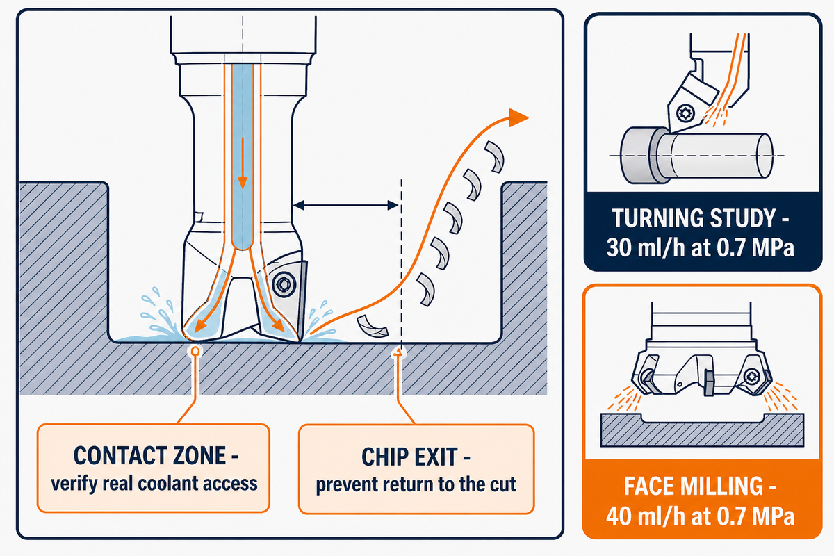
Once operation geometry and part support are defined, coolant still is not a checkbox. Delivery mode, fluid condition, access, pressure, flow, nozzle position, enclosure, and chip path determine whether fluid reaches the active zone. Nominal flood or minimum-quantity lubrication can look adequate from outside the cut while chips recirculate in a pocket or the edge loses access at depth.
One milling experiment used a 100 × 100 × 6 mm Ti-6Al-4V workpiece, a 20 mm four-flute titanium-aluminum-nitride-coated carbide tool, 3-times-diameter overhang, and minimum-quantity lubrication at 0.7 MPa and 40 ml/h. An earlier turning study used 30 ml/h and also stated 0.7 MPa, but it involved a different operation and test system. Those dimensions make each result interpretable; they do not make the 10 ml/h difference a transferable recommendation. Record the delivery envelope whenever a cut is compared.
Chip form is both an output and a control signal. Long or recut chips can redirect heat and damage a finished surface. Discoloration, edge buildup, burr change, or an altered chip rhythm may signal a changing system, but no single visual symptom proves its cause. Check edge state, engagement, coolant access, and evacuation together, then change one separating variable.
Fluid selection also has a workplace-health boundary. OSHA reports that poorly managed metalworking-fluid exposure has been associated with skin, eye, and respiratory effects, including bronchitis and asthma, and with rare cases of hypersensitivity pneumonitis. This guide cannot select a fluid, exposure limit, ventilation system, or protective equipment for a site. Use the current safety data, workplace assessment, fluid-management plan, and applicable rules.
Surface Integrity Needs More Than a Dimensional Pass
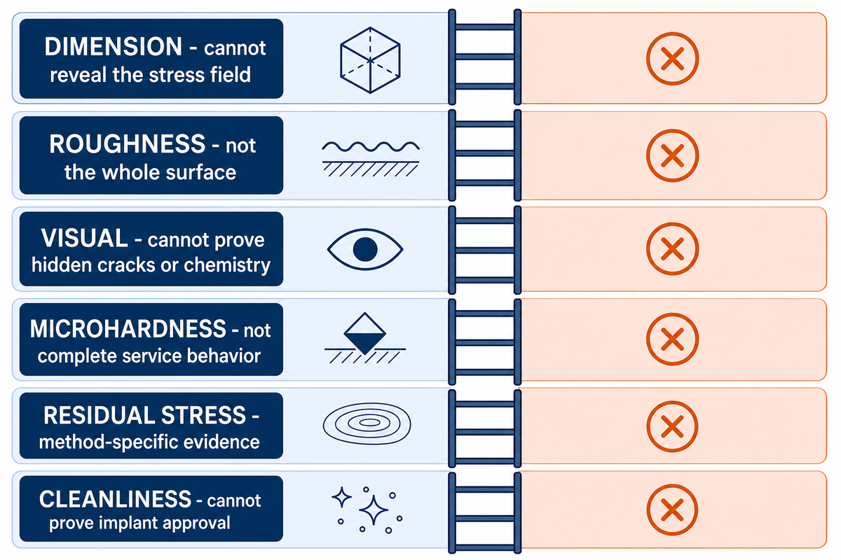
Even when the tool and the workpiece produce a dimensionally acceptable feature, the surface condition may remain unresolved. Surface roughness, burrs, smearing, heat-affected appearance, microhardness change, residual stress, subsurface deformation, and contamination answer different questions. Inspection planning should select the characteristics tied to function instead of assuming that a single roughness value represents the whole surface.
Residual stress is especially easy to miss. Published titanium-alloy research found nonlinear relationships among cutting parameters and residual-stress response and reported model error rather than a universal direct conversion. Coordinate measurement or calipers cannot reveal that stress field. If surface integrity matters to the released function, the drawing owner must define the applicable method, location, sampling, and acceptance rule.
| Characteristic | What it can reveal | What it cannot prove alone |
|---|---|---|
| Dimension and geometry | Size, form, orientation, or location in a defined state | Subsurface or residual-stress condition |
| Roughness metric | A specified profile statistic under a defined method | All waviness, lay, damage, or function |
| Visual inspection | Visible burrs, color, chips, obvious marks | Hidden cracks, stress, or chemistry |
| Microhardness | Localized hardness response under a defined test | Complete service behavior |
| Residual-stress method | Method-specific stress information | Causation without a process record |
| Cleanliness record | Defined residues or process controls | Biocompatibility or implant approval |
That cited finish-turning experiment also warns against compressing surface evidence. Its roughness-quality analysis did not give a conclusive result for the uncoated tool even though wear differences were large. Tool wear, surface finish, and statistical confidence are connected but not interchangeable. For custom titanium parts, bind every acceptance result to feature, location, method, tool state, material lot, and revision.
Titanium Chips, Dust, and Metalworking Fluids Need a Documented Safety Plan
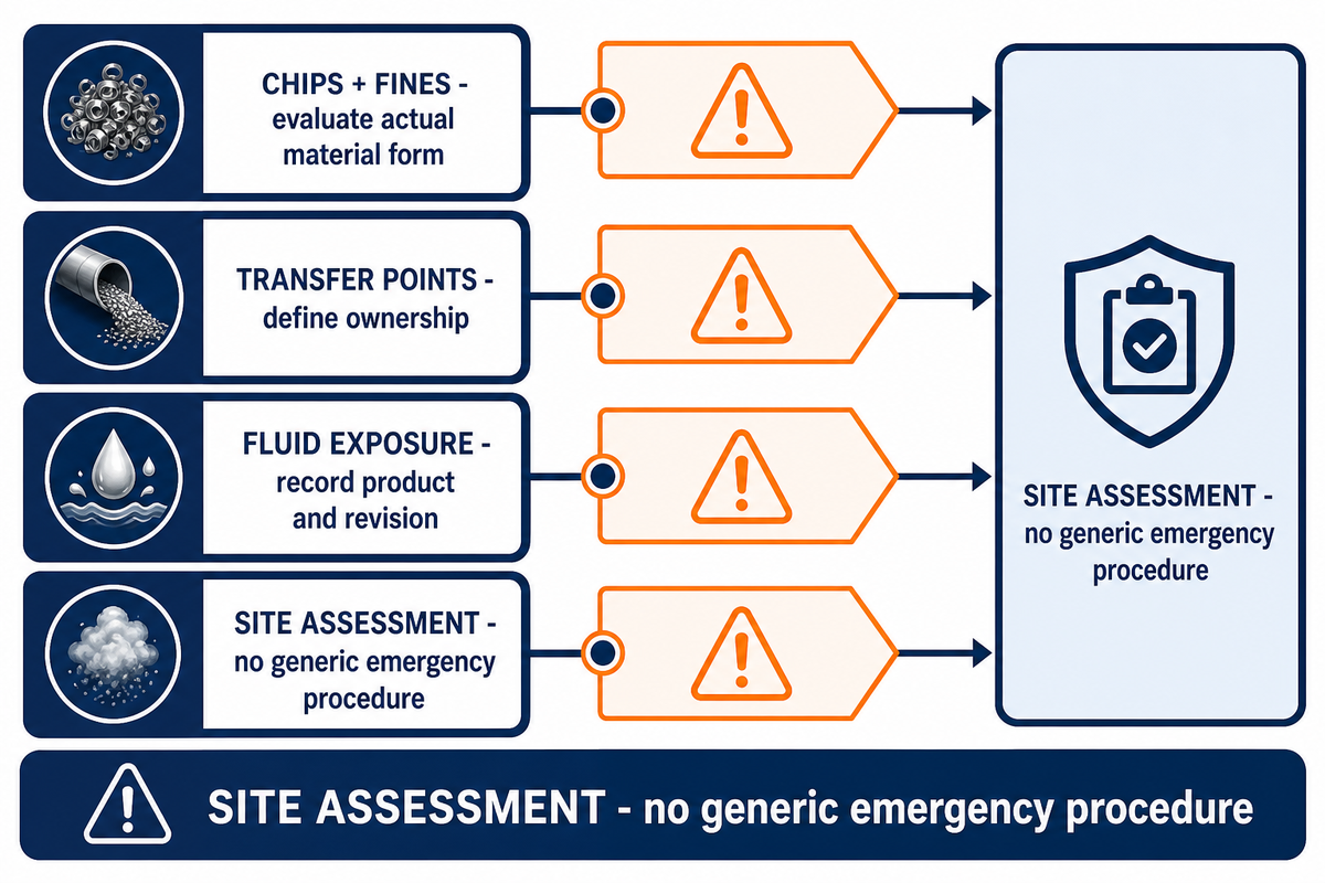
Titanium chips or dust, ignition hazards, and metalworking-fluid exposure require a site-specific safety assessment. The shape, size, moisture or contamination state, collection method, accumulated quantity, ignition sources, equipment, and applicable jurisdiction can change the hazard. This web article cannot prescribe firefighting, housekeeping, extraction, or personal protective equipment decisions.
“Any combustible material can burn rapidly when in a finely divided form.”
U.S. Occupational Safety and Health Administration, Combustible Dust
That statement is a screening boundary, not a titanium-specific emergency procedure. Evaluate the actual chips and fines, process equipment, collection system, and current site rules with qualified safety personnel.
As a conservative editorial screening boundary, treat wet-looking chips, a closed machine, and a familiar coolant as observations rather than evidence that every hazard has been eliminated. Material may move between the cutting zone, conveyor, separator, vacuum, container, and waste stream. The plan should define ownership at each transfer, prohibited mixtures, inspection and housekeeping records, and the response to an abnormal condition without improvising from a generic blog.
Occupational exposure needs the same specificity. OSHA’s metalworking-fluid guidance discusses multiple health effects and management factors, but it does not turn one fluid name into a safe-use approval. Record the product and revision, concentration-control method, mist or aerosol assessment, maintenance, enclosure or ventilation, worker tasks, and medical or industrial-hygiene escalation route required by the site.
Separate Titanium Drift by Event, Cause, and Evidence
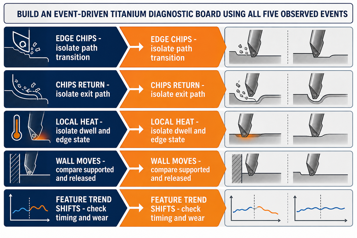
Titanium process drift is easier to investigate when the first question is “what changed, where, and after which event?” A visible symptom can narrow the next test, but it cannot identify a cause by itself. Hold the other cut states constant, document the time and path location, and compare the suspected source against a known baseline.
| Observed event | Source to isolate first | Evidence to compare | What the event cannot prove |
|---|---|---|---|
| Edge chips at entry or exit | Path transition and local engagement | Edge location, path position, and contact interval | A universal coating or speed correction |
| Long chips return to the cut | Chip exit path and coolant access | Chip form, recut marks, and contact-zone delivery | Material chemistry or tool wear as the sole cause |
| Local heat color or buildup appears | Dwell, rubbing, and edge condition | Tool edge before and after the affected path segment | Subsurface condition or service damage |
| Thin wall moves after release | Support, sequence, and measurement state | Supported and released geometry at the same interval | Residual-stress magnitude or cause |
| Bore, thread, or finish trend shifts | Tool state, evacuation, and sampling point | Wear location, chips, surface evidence, and timing | That every feature in the setup changed equally |
This diagnostic table cannot identify material microstructure, hidden porosity, residual stress, internal defects, fluid exposure, combustible-dust risk, measurement uncertainty, or regulatory requirements. It also cannot prove causation when several variables changed together. Those limits are deliberate: process observations must stay paired with material, safety, and quality evidence.
A published finish-turning study records tool-wear and surface-response results together. That pairing illustrates why one observation should not stand in for the complete evidence set; it does not validate the diagnostic table above.
Compare each event across a defined cut interval, not as an isolated snapshot. A load change without an edge check may be fixture or engagement drift. A surface mark without chip history may be recutting. A worn edge without material-lot identity may be a transfer error. Select the next bounded test, change one condition, and do not authorize a universal correction from the first symptom.
Current Document Checks: NFPA 660 After NFPA 484
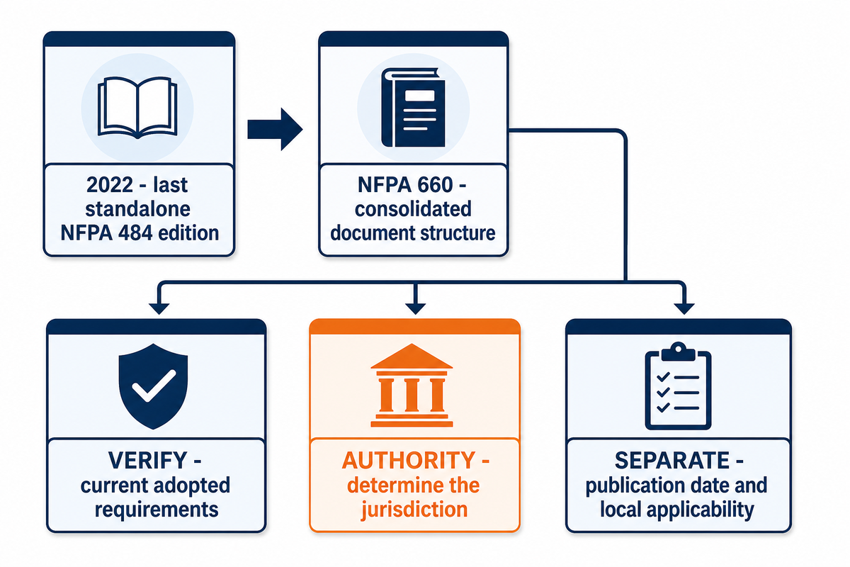
Because process observations cannot close a standards question, safety references must be checked by current edition and adopted jurisdiction. NFPA identifies the 2022 edition of NFPA 484 as the last standalone edition and states that the material was consolidated into NFPA 660. A procedure that cites NFPA 484 without checking the current document structure may be relying on an obsolete map even if its underlying hazard concern remains valid.
In practice, the check is documentary: identify the operation and material form, determine the authority having jurisdiction, confirm the current adopted requirements, and involve qualified safety personnel. As an editorial legal-scope boundary, treat publication date and local applicability as separate checks; verify the controlling adopted requirement rather than using a standards landing page as a substitute for the controlling edition or site assessment.
The NFPA 484 development page provides the transition context. OSHA’s combustible-dust and metalworking-fluid pages provide federal safety context. Together they show why document currency, material form, and exposure route must be recorded; they do not provide a complete titanium-shop safety program.
Run a Bounded Titanium Trial Before Releasing a Cutting Condition
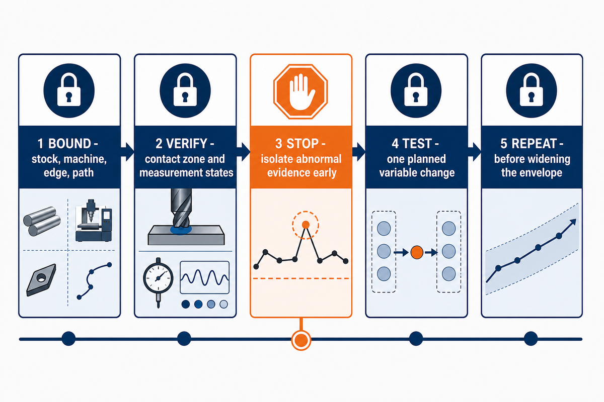
A published or previously successful number becomes a candidate starting point only after the new cut is bounded. Use a short trial sequence that keeps the material, tool, path, coolant access, support, and observation interval identifiable. The objective is to learn whether the cutting condition transfers, not to qualify a supplier or assemble a request-for-quotation package.
The CNC machining DFM guide explains how geometry affects manufacturability. The sequence below starts later, at the point where a specific titanium cut must be tested without changing several process variables at once.
| Trial check category | Required process record | Decision protected |
|---|---|---|
| Isolate the starting stock | Material lot, form, condition, and a baseline coupon | Is this trial tied to one identifiable material state? |
| Confirm the machine baseline | Warm-up state, work offset, runout, and signal scaling | Can machine drift be separated from cut drift? |
| Lock the edge system | Tool, edge preparation, coating, holder, and overhang | Can later wear be compared against one starting edge? |
| Lock the engagement path | Operation, entry, exit, axial and radial engagement | Are load changes attributable to a known path segment? |
| Verify contact-zone access | Coolant delivery and the actual chip exit route | Can chips leave without returning to the cut? |
| Define measurement states | Supported and released observations at fixed intervals | Will part movement be separated from measurement timing? |
| Set an early stop trigger | Edge damage, recutting, unstable load, heat evidence, or movement | Will an abnormal event stop the trial before evidence is mixed? |
| Run a short staged cut | One planned variable change and a fixed cut interval | Did the trial isolate the intended comparison? |
| Compare the evidence trend | Edge, chip path, load context, surface, and released geometry | Do several observations support the same bounded conclusion? |
| Repeat before widening | Defined interval, stop condition, and a second comparable run | Is the condition repeatable inside the same cut envelope? |
This sequence keeps a prototype observation from silently becoming a production claim. It also prevents a strength-and-lightweight material narrative from replacing the evidence needed for CNC-machined titanium parts. A successful sample is useful, but a transferable cutting condition needs a defined material state, process state, observation interval, and trigger for a new trial.
Search language needs the same intent routing. Queries such as “titanium milling,” “turning titanium,” and “end mills for titanium” belong with operation and tooling evidence. Questions about thin-wall movement, edge chipping, or chip recutting belong with bounded process diagnosis. “Stainless steel CNC” and “Titanium 3D printing” are separate material or process comparisons, not proof for this route.
When the remaining question moves from process education to project fit, use Zhenling’s titanium project-fit criteria. That solution page owns drawing-specific service, configuration, quotation intent, and searches for CNC machining services. This guide does not promise size, tolerance, volume, certification, price, or lead time.
Frequently Asked Questions
Can titanium be CNC machined?
Yes. The cited studies document titanium turning and milling, while each drilling or finishing route still needs its own validated grade, tool, thermal-chip, support, and inspection state.
After a bounded trial, the useful question is not simply whether a machine can cut titanium. It is whether the exact grade, form, route, geometry, tool, engagement, coolant access, chip path, support, and observation plan can produce acceptable evidence repeatedly. Titanium components range from simple stock-like features to complex titanium thin walls and pockets. Validate the specific feature and released state instead of transferring one generic parameter.
Why is titanium so difficult to machine?
Titanium concentrates local heat, edge load, elastic response, and chip-control sensitivity, so small changes in engagement, support, or coolant access can accelerate wear or surface damage.
Low thermal conductivity can retain heat near the tool, while material strength and ductility keep the edge loaded. Rubbing or unstable engagement can harden the local surface and accelerate wear. Long chips, poor coolant access, tool overhang, weak support, and thin-wall vibration can amplify the problem. The exact balance depends on the grade of titanium, material condition, operation, tool, and workpiece geometry.
What RPM or cutting speed should be used for titanium?
There is no defensible universal RPM or cutting speed for titanium; calculate RPM from the selected surface speed and diameter inside a validated operation and tooling envelope.
RPM depends on cutting speed and tool or workpiece diameter. A valid starting condition also needs the exact titanium alloy and state, operation, tool material and geometry, coating, radial and axial engagement, feed basis, coolant delivery, overhang, support, and acceptance plan. Published numbers are test envelopes. Use machine, toolmaker, material-owner, and controlled trial evidence for the actual feature rather than copying one value.
What should stop a titanium trial before parameters are transferred?
Stop and isolate the cause when edge chipping, chip recutting, unstable load, local heat evidence, surface drift, or released-part movement leaves the original cut envelope.
Stopping does not diagnose the cause. Record the path location and cut interval, preserve the tool and chips where practical, compare supported and released geometry, and check whether material state, edge, engagement, coolant access, chip exit, or support changed. Resume with one bounded change and a defined observation point. Do not transfer the original parameter merely because the first part remained dimensionally acceptable.
Does titanium’s corrosion resistance guarantee a durable machined part?
No. Corrosion resistance is alloy-, environment-, surface-, and application-specific.
It does not prove geometry, fatigue life, cleanliness, surface integrity, coating compatibility, or regulatory approval. Connect the alloy, environment, loads, finish, cleaning, inspection, and service requirements for the actual part. Also separate general alloy behavior from the effects of machining damage, contamination, residual stress, joining, and later surface treatment. Each claim needs evidence for the intended exposure and service condition. A coupon or certificate can answer only the question it was designed to test. It cannot establish the effect of an unrecorded finish, trapped residue, mixed-metal contact, or a later cleaning step. As an editorial evidence rule, keep the corrosion claim tied to the declared alloy state, surface route, test method, environment, duration, and acceptance criterion.
How This Guide Was Built
Research for this guide combines current ASTM product-form scopes, OSHA workplace guidance, NFPA document-transition information, peer-reviewed titanium research, and bounded vendor-authored practitioner context. The Titanium Cut Stability Envelope is an editorial organization tool, and the event-driven diagnostic table is not a validated causal model. No private Zhenling production result, certification, patent ownership, or universal parameter was added.
References & Sources
- ASTM B348/B348M-25: Titanium and Titanium-Alloy Bars and Billets ASTM International
- ASTM B265-25: Titanium and Titanium-Alloy Strip, Sheet, and Plate ASTM International
- Effect of Ti-6Al-4V microstructure in micromilling PubMed record
- Machinability of additively manufactured titanium alloys peer-reviewed review in PubMed Central
- Tool wear and surface response in finish turning Ti-6Al-4V peer-reviewed article in PubMed Central
- Machining parameters and residual stress in titanium alloy peer-reviewed article in PubMed Central
- Machining dynamics of thin-walled Ti-6Al-4V peer-reviewed article in PubMed Central
- Minimum-quantity-lubrication milling experiment Journal of Manufacturing and Materials Processing
- Combustible Dust U.S. Occupational Safety and Health Administration
- Metalworking Fluids: Health Effects U.S. Occupational Safety and Health Administration
- NFPA 484 standard development and consolidation notice National Fire Protection Association
- Turning formulas and definitions Sandvik Coromant supplier reference
- Titanium corrosion and surface-state context International Titanium Association publication
- A systems approach for successful titanium machining Kennametal-engineering-authored vendor article published by Modern Machine Shop
- What you need to know about chip formation Seco Tools supplier reference
- Metalworking Fluids: Safety and Health Best Practices Manual U.S. Occupational Safety and Health Administration
- Indexable milling tool formulas and definitions Sandvik Coromant supplier catalogue