Get in touch with Zhenling Company

3-Axis vs 4-Axis vs 5-Axis CNC is not a contest in which the machine with more motion automatically wins. Select the lowest-burden route that can reach the features, protect their datum relationships, support the planned quantity, and generate the inspection evidence required by the drawing.
Updated August 2026 · Written for engineers, procurement teams, quality staff, plant managers, and owners sourcing custom machined parts.
Direct answer
Choose 3-axis for accessible prismatic features, 4-axis when one rotary direction removes the right setups, and 5-axis when compound orientations or a changing tool vector justify two rotary axes. Axis count alone does not set tolerance, speed, or accepted-part cost.
Quick Specs: Route Questions Before the Quote
- How many independent tool-access directions does the part require?
- Which features must hold position or orientation to one shared datum?
- Does the tool vector change during cutting, or can rotary axes index and lock first?
- What measurement method and conformity decision rule will govern acceptance?
Scope note: this is a machining-service route guide, not a machine-buying price list. Equipment prices, generic hourly rates and supplier-independent tolerance promises are omitted because the evidence examined didn’t justify confident global values.
3-Axis vs 4-Axis vs 5-Axis CNC at a Glance
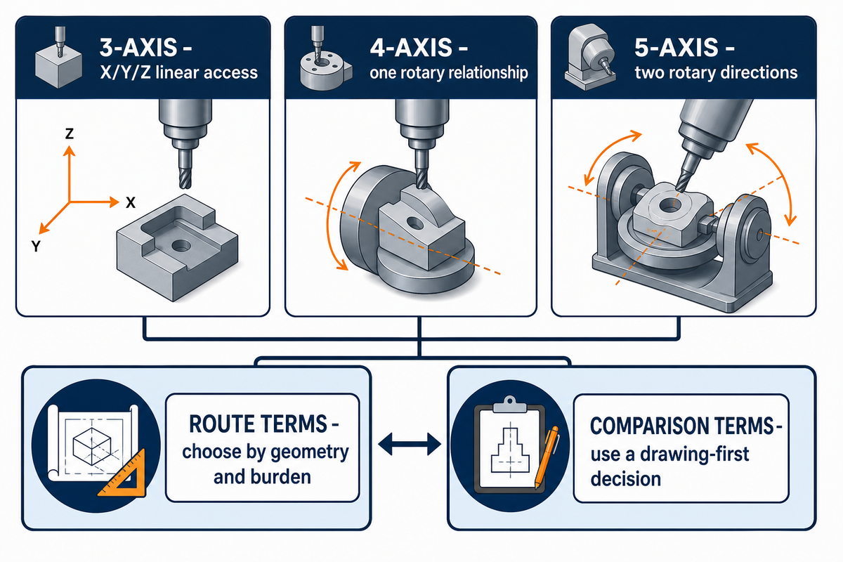
Axis count describes controlled directions of relative motion between the cutting tool and workpiece. Three-axis machining uses the X-axis, Y-axis, and Z-axis as linear axes; four-axis adds one rotational direction; five-axis adds two rotational axes. In supplier shorthand, 3 axis CNC machining, 4 axis CNC, and 5 axis CNC machining label those route families. Machine architecture varies, so a universal statement that both spindle and workpiece rotate is inaccurate.
ISO 10791-6 covers machining centres with 3 linear axes plus 1 or 2 rotary axes. It also describes several arrangements: rotary motion may sit in the spindle head, on the workpiece side, or in a swivel-head/rotary-table configuration. Useful comparisons begin with what motion and access the route controls–not which component appears to move in a single picture.
| Route | Controlled motion | Useful starting fit | Limitations / not suitable for |
|---|---|---|---|
| 3-axis | X/Y/Z linear axes | Open prismatic geometry, plates, accessible pockets and holes | Needs extra orientations when features sit on other faces |
| 4-axis | X/Y/Z plus 1 rotary axis | Radial holes, wrapped paths, indexed sides and cylindrical work | Cannot independently orient features around a second rotary direction |
| 5-axis | X/Y/Z plus 2 rotary axes | Compound orientations, obstructed access and freeform tool-vector control | Programming, collision, calibration and workholding burden may exceed the benefit on simple parts |
What’s the Difference in Common CNC Route Terms?
- Three-axis terms: For understanding 3-axis, read 3-axis milling, 3-axis CNC milling, traditional 3-axis, and 3-axis milling machines as CNC milling machines that use 3 axes to move along three linear directions—the X, Y, and Z linear axes of movement—within the wider types of CNC.
- Fourth-axis terms: A 4th axis is one additional axis, commonly an A-axis, so the workpiece turns around the X-axis and can rotate through indexed or continuous 4-axis machining; 4-axis machining allows a machine shop to index multiple sides, but access to 4 sides in a single setup depends on workholding, travel, and clearance, while 4-axis milling on a 4-axis CNC machine still controls only one rotary relation.
- Five-axis terms: The two main types of 5-axis are indexed 3+2 and fully continuous 5-axis machining; both control 5 axes; a buyer may encounter B axis and C axis—also written B-axis and C-axis, or B and C—in a machine manual, but those labels are configuration-specific, while the axes in 5-axis CNC describe motion in relation to the cutting tool and workpiece.
- Route terms: For parts that require complex 3D shapes, 5-axis CNC milling or 5 axis machining may provide a higher level of flexibility, but the capabilities of 5-axis and flexibility and precision remain separate claims; CNC machined parts benefit from 5-axis only when the added motion removes a named burden.
- Comparison terms: The phrase “what’s the difference” should lead buyers to compare 3-axis and 5-axis CNC, 4-axis and 5-axis machines, and 4-axis and 5-axis routes against the drawing, then select the right CNC process instead of ranking machine types by axis count alone.
Advantages and limitations: an added axis can remove a fixture or unlock an approach direction, but the value exists only when that motion addresses a feature the lower-axis route cannot handle with acceptable setup and evidence burden.
When 3-Axis Machining Is the Lowest-Burden Capable Route
Three-axis machining is the better route when the required features remain reachable with stable tooling and the remaining orientations do not threaten functional relationships. Several operations may still be needed; the decision turns on operation order, workholding feasibility, available locating datums, quantity, and inspection—not on whether the model looks visually simple.
In an archived 1995 University of Maryland setup-planning model for prismatic parts on a 3-axis vertical machining centre, researchers identify 3 determinants: precedence among operations, feasibility of vise workholding, and availability of datum faces. That is a stronger test than “simple versus complex,” but it remains a bounded planning model rather than current universal shop data. NIST also documented a vertical machining workstation for a family of prismatic parts with integrated process planning and NC-code generation.
Can a 3-axis CNC machine make a multi-sided part?
Yes. Controlled reorientation lets a 3-axis CNC machine make a multi-sided part through a tombstone, dedicated fixture, or divided operations. Buyers must decide whether those transfers preserve critical datum relationships at an acceptable cost. If every new orientation needs fresh alignment, probing, inspection, or a custom fixture, a rotary-axis route deserves evaluation. If the features are open, quantities support a repeatable fixture, and relationships across faces are not critical, 3-axis may remain the lower-burden route.
Example: a rectangular electronics enclosure has top pockets, side connector openings, and a noncritical bottom relief. Two stable fixtures may serve production better than placing several housings on a smaller trunnion. Batch density and unattended capacity can outweigh the appeal of “one setup.” This is a route hypothesis for supplier review, not a guaranteed answer.
When a Fourth Axis Removes the Right Setup
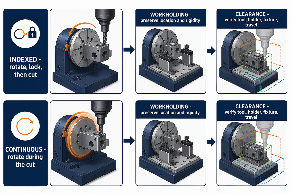
Four-axis CNC machining adds one rotary relationship to X/Y/Z cutting. On a common table-mounted configuration, that additional rotational axis is the A-axis, although the named axis depends on machine architecture. It fits parts whose key features can be reached by indexing or cutting around a common rotary direction, such as radial holes, flats around a shaft, wrapped slots, or repeated faces. Independent compound orientations erase that advantage.
Indexed 4-axis work rotates the part, clamps the rotary axis, and continues traditional linear cutting. Continuous 4-axis work rotates during the cut, which may suit helixes or wrapped geometry. Quotations should specify which mode is suggested because the programming, prove-out, surface path, and inspection consequences differ.
What are the key differences between 3-axis and 4-axis CNC machining?
Three-axis machining reaches features through X/Y/Z motion and relies on fixtures or manual orientation for other sides. Four-axis machining adds a rotary axis that can index or move during cutting. The practical difference is not “one more degree of quality.” Value appears when a single rotary relationship replaces enough handling, datum transfer, and idle time to offset rotary workholding, programming, and clearance constraints.
“We needed a setup … with enough clearance for machining on both sides.”
That specific case involved a horizontal machining and workholding problem. Its value here is the reasoning—access, rigidity, pallet geometry, and operator handling—not its cycle or tolerance numbers.
5-Axis Is Two Decisions: Indexed 3+2 or Simultaneous Motion
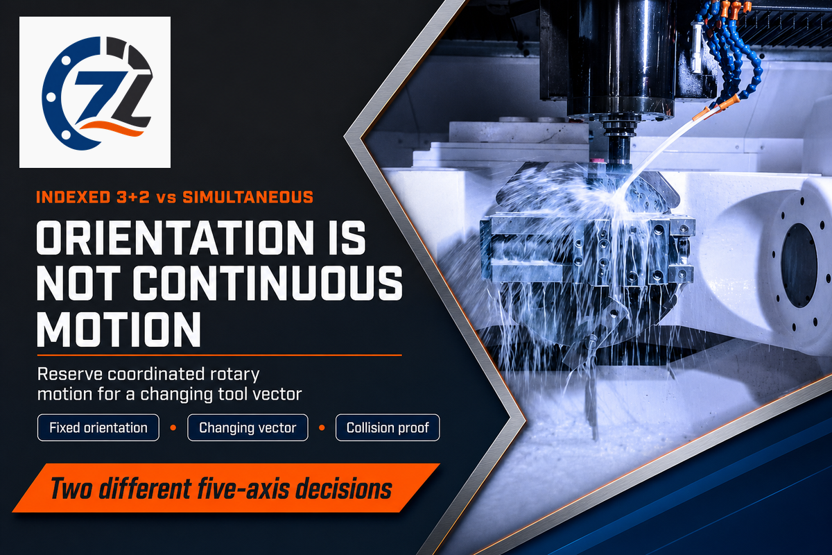
Indexed 3+2 machining positions two rotary axes before X/Y/Z cutting resumes; simultaneous 5-axis machining coordinates linear and rotary motion during the cut. On either route, the milling machine, control, postprocessor, workholding, and cutting tool must be treated as one configured system. Choose indexed work when orientation unlocks the feature. Reserve simultaneous 5-axis milling for changing tool-vector, freeform, swarf, interference-avoidance, or surface-continuity requirements that cannot be met by fixed orientations.
American Machinist’s technical article “When 2+3 Doesn’t Equal 5” illustrates the motion distinction. ISO 10791-6 also addresses coordinated motion and tool-centre-point control. Neither source says simultaneous motion is the default winner.
| Decision field | Indexed 3+2 | Simultaneous 5-axis |
|---|---|---|
| Rotary motion during cut | Positioned and locked | Coordinated with X/Y/Z |
| Primary need | Compound access | Changing tool vector |
| Programming burden | Lower, configuration-dependent | Higher; post and machine model matter |
| Not suitable for | Continuous freeform orientation changes | Simple fixed-orientation parts where added prove-out brings no return |
Is 5-axis CNC machining faster?
Sometimes, but cutting time is only one component of the process. Five-axis can eliminate fixtures, handling, positioning, or long-tool access; simultaneous paths may also add programming, simulation, postprocessor, calibration, and first-piece verification effort. In a 2026 NIST MEP success story, McQuillen Manufacturing president Rob McQuillen said the project helped reduce setup times by up to 30% after training, probing, and process work. That bounded testimonial is evidence that five-axis improvement is possible, not a universal saving.
The 8-Input Route Burden Ledger
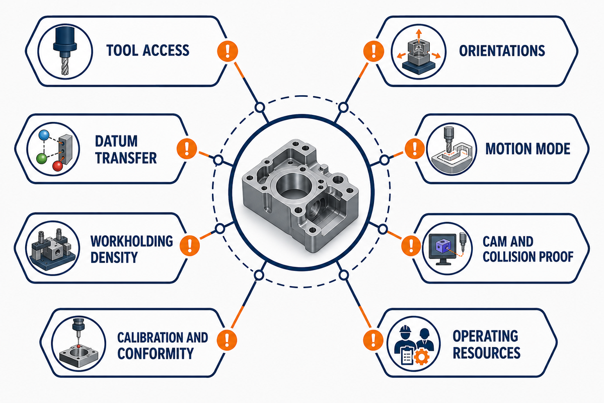
The 8-Input Route Burden Ledger is a screening aid, not a complete machine error budget. It identifies the first burden that may justify a more complex route: access, orientations, datum transfers, motion mode, workholding density, CAM/collision proof, machine-specific calibration/conformity, and operating resources. Supplier evidence must finish the decision.
| Input | Question to answer | Escalation signal | Limitations / not suitable for |
|---|---|---|---|
| 1. Tool access | Which approach vectors are blocked? | Shorter, safer tool orientation needs a rotary move | Does not solve an undefined feature or tolerance |
| 2. Orientations | How many independent directions are required? | Compound faces exceed one rotary relationship | Visual complexity alone is not evidence |
| 3. Datum transfer | Which relationships cross setups? | Re-clamping breaks a functional relationship | One setup still needs valid workholding and probing |
| 4. Motion mode | Index and lock, or move during the cut? | Tool vector must change continuously | Simultaneous motion is unnecessary for fixed orientations |
| 5. Workholding density | How many accepted parts fit per cycle? | Extra axes remove more handling than they remove capacity | A small trunnion may reduce batch density |
| 6. CAM and collision proof | Is the post/machine/fixture model verified? | Rotary clearance cannot be proven with a simpler path | Software availability does not prove shop competence |
| 7. Calibration and conformity | What error evidence and decision rule apply? | Rotary/coordinated error or uncertainty is material | A standard test piece is not the buyer’s production part |
| 8. Operating resources | Do energy, coolant, idle time, skill, or utilization alter the route? | Long cycles or low use make auxiliary cost material | No universal resource number is supplied |
Ledger rule: move to a higher-axis route only when the proposal names the burden it removes and the new evidence burden it creates.
Compare Cost per Accepted Part, Not Machine Rate
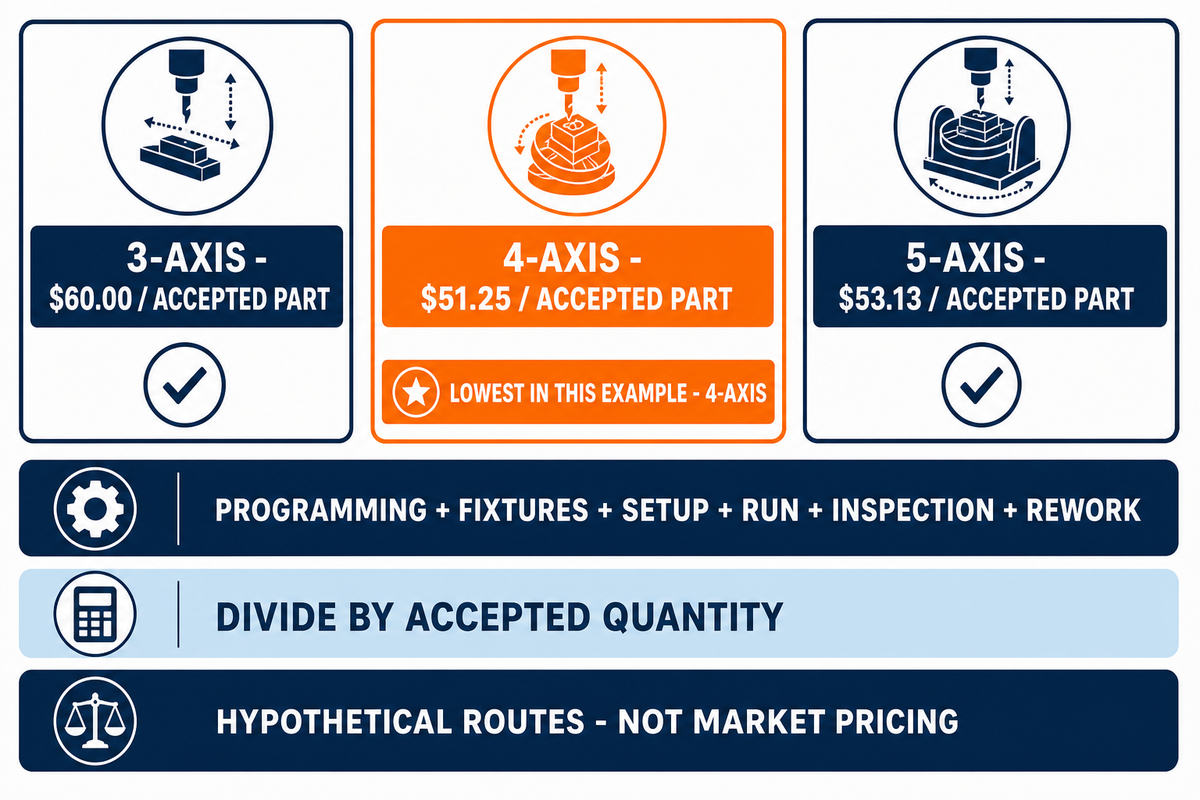
A 3 axis vs 4 axis vs 5 axis CNC cost comparison should normalize route cost by the quantity that passes the agreed acceptance rule. Add programming, fixtures, setup, machine and auxiliary run, inspection, and rework; then divide by accepted quantity. The model avoids universal hourly prices and exposes where a higher machine rate may—or may not—remove other costs.
Three-Route Accepted-Part Cost Comparator
(Programming + Fixtures + Setup + Machine/Auxiliary Run + Inspection + Rework) ÷ Accepted Quantity
Use supplier quotation fields. Add energy or auxiliary-system cost only when it’s material and documented.
Worked example: assume each route produces 80 accepted parts. Values below are hypothetical buyer inputs only; they show the arithmetic, not market pricing or a Zhenling quotation.
| Hypothetical route | Cost inputs | Total | Cost / accepted part |
|---|---|---|---|
| 3-axis | $600 + $900 + $750 + $1,800 + $450 + $300 | $4,800 | $4,800 ÷ 80 = $60.00 |
| 4-axis | $750 + $600 + $500 + $1,650 + $400 + $200 | $4,100 | $4,100 ÷ 80 = $51.25 |
| 5-axis | $1,200 + $350 + $350 + $1,900 + $350 + $100 | $4,250 | $4,250 ÷ 80 = $53.13 |
In the example, 4-axis is the lowest-cost route. Change fixture quantity, accepted yield, programming, energy, or inspection and the result can move. Quotations should expose those inputs rather than asserting that one axis count is inherently cheaper.
More Axes Do Not Automatically Mean Tighter Accepted Parts
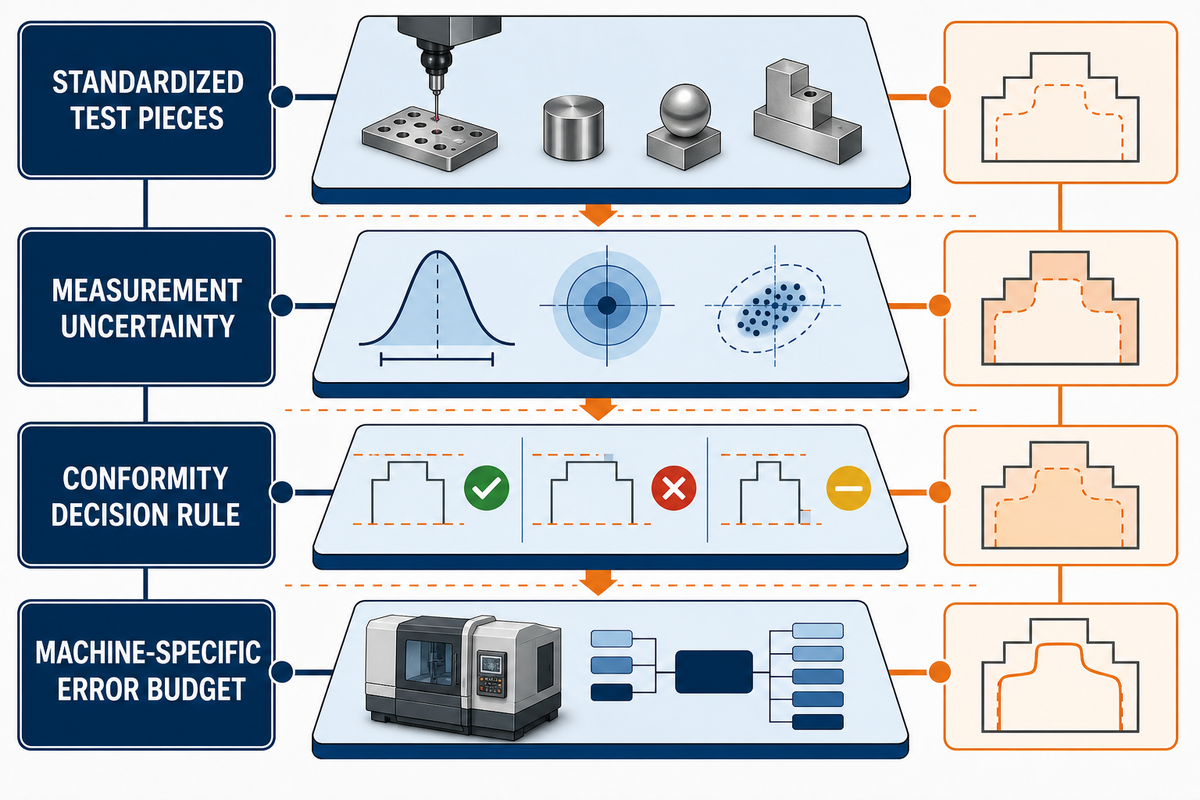
Axis count can change access and setup transfer, but accepted-part accuracy still depends on machine-specific geometric, rotary, thermal, load, dynamic, tool, workholding, material, and measurement effects. Standardized test pieces can characterize machining-centre performance; they cannot by themselves decide whether a buyer’s production feature conforms to its drawing.
ISO 10791-7:2020 uses finished test pieces to assess cutting accuracy for machining centres with 3 to 5 simultaneous axes. ISO 230-12:2022 describes several error contributors and test objectives. Standardized part tests are machine-performance evidence, but the buyer’s released part still needs its own conformity route.
Near a specification limit, ISO 14253-1:2017 requires measurement uncertainty to enter the conformity decision. Supplier and customer should agree on a decision rule when uncertainty creates a zone in which a measured value alone cannot prove conformity or nonconformity.
In a 2020 University of Wisconsin–Madison ultra-precision experiment, rotary-axis rigidity, tool stiffness, position/orientation errors, and measurement uncertainty affected the reported setup. That study does not rank every 3-axis and 5-axis machine; it shows why a nominal configuration is not a machine-specific error budget.
Acceptance rule: ask what was measured, with which method, under which state, and which decision rule turned the result into “accept” or “reject.”
Match Part Geometry to the Lowest-Burden Capable Route
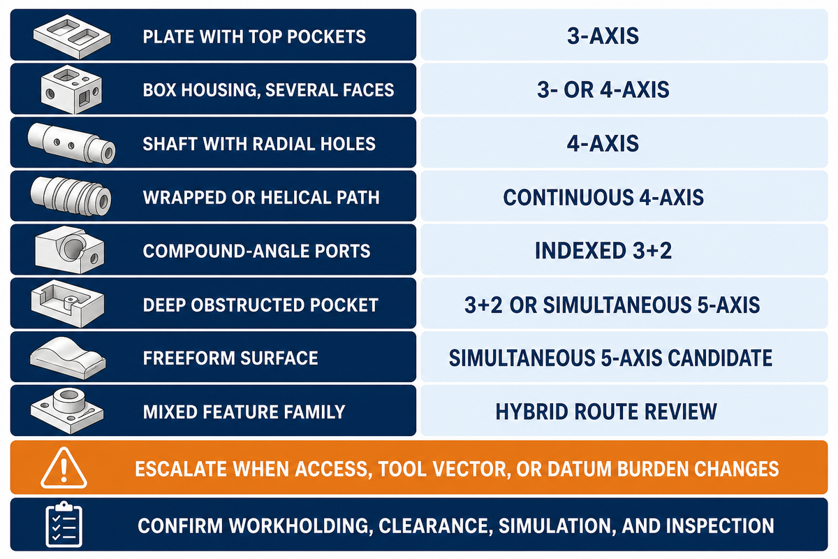
Geometry should select the starting route through feature access, orientation, shared datums, tool reach, and surface continuity. The same framework resolves 3-axis vs 5-axis CNC and 3 vs 4-axis CNC comparisons without treating axis count as a quality grade. Suppliers may propose a different route when quantity, material, machine layout, batch density, probing, or inspection changes the burden. Used as a screening aid, the matrix below exposes escalation triggers.
| Part scenario | Starting route | Why | Escalation trigger | Limitations / evidence needed |
|---|---|---|---|---|
| Plate with top pockets | 3-axis | All features accessible from Z | Critical side feature appears | Confirm flatness and workholding |
| Box housing, several faces | 3- or 4-axis | Route depends on datum transfer and batch fixture | Repeated radial indexing removes transfers | Compare parts per cycle |
| Shaft with radial holes | 4-axis | Features share one rotary relationship | Compound angles leave the rotary plane | Confirm runout and axis location |
| Wrapped or helical path | Continuous 4-axis | Cut follows one rotary axis | Tool vector needs a second rotation | Verify feed interpretation |
| Compound-angle ports | Indexed 3+2 | Orientation, not continuous motion, unlocks access | Vector changes during cut | Prove holder and fixture clearance |
| Deep obstructed pocket | 3+2 or simultaneous 5-axis | Tilt may allow a shorter tool | Continuous avoidance needed | Check stick-out, holder and collision model |
| Freeform surface | Simultaneous 5-axis candidate | Tool vector and engagement change | Surface can be segmented into fixed orientations | Require post, simulation and test-piece evidence |
| Mixed feature family | Hybrid route review | No single axis label explains every operation | One machine can consolidate verified operations | Return assumptions and inspection stages |
Scenario: a valve-style body has planar flange faces, radial ports, and 2 compound-angle bores tied to one datum system. Planar work does not justify simultaneous motion; the compound bores may justify indexed 3+2. If complex geometries inside a transition require the tool vector to change while cutting, simultaneous 5-axis becomes a separate, evidence-backed machining operation rather than a label applied to the entire part. The selected axes must therefore follow the feature relationship, not the appearance of the whole model.
What to Put in an Axis-Route RFQ
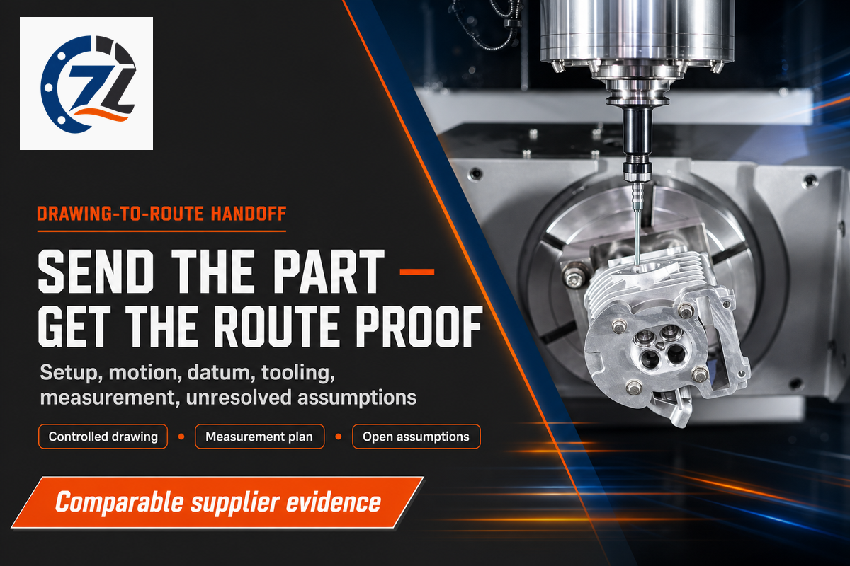
An axis-route request for quotation should define the part and acceptance need, then ask the supplier to return its setup, motion, datum, tooling, measurement, and unresolved assumptions. NIST identifies machine setup, machine kinematics, and product tolerances as distinct information classes for verification. Ask for evidence without dictating the supplier’s exact manufacturing method.
University of Florida CNC laboratory guidance also requires an accurate detail drawing, feature tolerances, finish requirements, tool details, and datum/zero locations for each operation.
Drawing-to-Route Decision Packet
- Controlled 2D drawing, revision, units, and usable 3D model.
- Material grade, product form, delivery condition, and quantity.
- Critical features, datums, finish, secondary operations, and records.
- Supplier’s proposed setup count and indexed/simultaneous motion mode.
- Access, tool reach, fixture, batch-density, and collision assumptions.
- Machine-specific calibration or test evidence relevant to critical features.
- Measurement method, uncertainty/decision rule where material, and reporting plan.
- Unresolved assumptions, exclusions, packaging, destination, and schedule basis.
Use Zhenling’s public 5-axis process fit screener to identify the first geometry questions, then check the package with the CNC RFQ readiness checker. These tools screen inputs; they do not approve a process or tolerance.
What Is Changing: More Axis Choice Requires More Process Proof
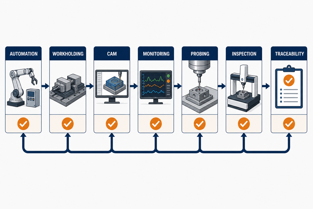
For 2026, buyer risk comes from treating one machine feature as the production system, not from a shortage of axis labels. Current evidence points toward integrated automation, workholding, CAM, monitoring, probing, inspection, and traceability. More motion expands access, while process proof determines whether that access produces accepted parts at a defensible cost.
EMO Hannover’s 25-page 2025 technical report repeatedly connects machine tools with automation, clamping, software, measurement, and digital traceability. The patent page for the 2025 publication US20250276421A1 lists China University of Petroleum (East China) as the assignee; the publication is another signal that digital-twin and feedback approaches remain active development areas, not Zhenling technology or proof of common adoption.
Interest in the exact comparison query has risen from a low United States base, but the series is volatile and does not prove machine-market growth. For 2026 sourcing, the actionable step is narrower: ask each supplier how its proposed route handles simulation, setup, probing, conformance, and repeat production before treating “5-axis” as evidence.
Frequently Asked Questions
Can a 3-axis machine cut all six sides of a part?
Yes, through controlled reorientation, fixtures, or additional operations.
A 3-axis machine can cut all 6 sides when the process includes suitable workholding and orientation changes. The decision is whether those transfers preserve functional relationships and remain economical for the quantity. A 4-axis or 5-axis route becomes attractive when it removes important datum transfers, access conflicts, or handling, not merely because another side exists.
Is 4-axis CNC always simultaneous?
No—4-axis work may be indexed or continuous.
Indexed 4-axis work rotates the workpiece to a position, locks the rotary axis, and resumes X/Y/Z cutting. Continuous 4-axis work rotates during material removal. A supplier should state the proposed mode because tool paths, feed interpretation, surface path, prove-out, and inspection can differ even though both routes are called 4-axis machining.
Is 3+2 machining the same as simultaneous 5-axis?
No—3+2 positions and locks the rotary axes before X/Y/Z cutting, while simultaneous 5-axis coordinates linear and rotary motion during the cut for changing tool-vector requirements.
Both routes use a machine with 5 controlled axes, but they solve different problems. Indexed 3+2 is often enough for compound faces and angled holes that become accessible from fixed orientations. Simultaneous 5-axis is reserved for changing tool vectors, continuous freeform surfaces, swarf paths, or interference-avoidance needs that cannot be represented as separate locked orientations.
Does 5-axis machining guarantee tighter tolerances?
No, axis count cannot guarantee a finished-part tolerance.
Fewer setup transfers may remove one error source, while rotary, thermal, load, tool, fixture, material, dynamic, and measurement effects remain. Acceptance still needs a defined method and decision rule.
Does 5-axis always cost more per part?
No—accepted-part cost depends on programming, fixtures, setup, machine and auxiliary run, inspection, rework, and accepted quantity, not the axis label or hourly rate alone in practice.
A 5-axis route may carry higher programming, prove-out, or machine cost and still remove fixtures, handling, long tools, secondary operations, or rework. A 3-axis route may hold more parts per cycle and remain cheaper for accessible repeat geometry. Compare programming, fixtures, setup, machine and auxiliary run, inspection, and rework, then divide by accepted quantity. Supplier-specific values are required; generic hourly ranges do not answer the question.
What should I send for an axis-route quotation?
Send the controlled drawing and model, material condition, quantity, datums, finish, inspection and reporting needs, delivery inputs, plus any known process constraints or unresolved assumptions.
Ask the supplier to return setup count, motion mode, access and fixture assumptions, measurement plan, material uncertainties, exclusions, and schedule basis. That makes competing routes comparable without forcing every supplier to use the same machine.
Need a drawing-specific route review?
Send the controlled drawing, material condition, quantity, critical datums, and inspection needs. Zhenling can review whether conventional CNC milling service, indexed work, or a 5-axis CNC machining service is a plausible starting route.
How This Comparison Was Built
Source work combines current search-result analysis, public standards scopes, government and university research, a named trade case, and Zhenling’s published process-fit and RFQ tools. Public first-party pages are treated as attributed inputs rather than independent proof of capability. No customer outcome, default tolerance, legal entity name, or market price was inferred.
Related CNC Resources
References & Sources
- ISO 10791-6:2014 public scope International Organization for Standardization
- Estimation of Setup Time for Machined Parts University of Maryland
- Five-axis NC machining of compound sculptured surfaces Purdue University
- NIST MEP five-axis improvement case National Institute of Standards and Technology
- ISO 10791-7:2020 public scope International Organization for Standardization
- ISO 230-12:2022 public scope International Organization for Standardization
- ISO 14253-1:2017 public scope International Organization for Standardization
- Rotary-axis errors and uncertainty study University of Wisconsin–Madison
- Enabling Machining Vision Using STEP-NC National Institute of Standards and Technology
- CNC Mill Training Resources University of Florida
- EMO Hannover 2025 Technical Report Institute of Production Engineering and Machine Tools, Leibniz University Hannover