Get in touch with Zhenling Company

Updated August 2026
Direct answer: Tool Steel CNC Machining is the controlled production of tool-steel features by matching the exact grade, supplied condition, target hardness, feature geometry, and inspection method as one process chain. A family letter or hardness value alone cannot select a reliable route.
Tool Steel CNC Machining is a process-chain discipline, not merely a cutting operation. Tool steel is chosen for demanding combinations of wear resistance, toughness, hot strength, dimensional stability, or cutting performance. Those same properties can make machining less forgiving. In practice, the question isn’t simply whether a CNC machine can cut the steel. It is which material state should be cut, which features should wait until after heat treatment, and what evidence will show that the chosen route is still under control.
This guide helps engineers and buyers reason through those decisions without pretending that one speed, feed, allowance, or tool material fits every tool steel grade. It also separates common AISI letter-series language from current standard scopes. That distinction matters because an educational family label isn’t a complete material callout.
When machining tool steel for tool and die work, the ability to cut steel is only the entry condition. Tool steel machining shares some principles with general steel machining, yet machining steel in a hardened, carbide-rich, interrupted, or thermally sensitive state demands a narrower evidence window.
Why Tool Steel Machinability Is More Than a Grade Label
Tool steel machinability is a system response. Grade chemistry and carbide population matter, but so do microstructure, supplied condition, hardness, feature geometry, interruption, workholding, cutting tool, engagement, runout, thermal behavior, and the required surface. Change one of those inputs and the same grade may behave like a different machining problem.
That is why a machinability rating should be treated as a relative comparison under stated conditions, not a material constant. “Easy to machine” in an annealed bar doesn’t promise the same behavior after hardening. Nor does a good turning result predict drilling, tool steel milling, grinding, or wire electrical discharge machining. Each operation loads the edge and workpiece differently.
A 2026 experiment on AISI D2 at 60 HRC illustrates the problem. In that test, coated carbide led on tool wear, material removal rate, and cost, while cubic boron nitride produced lower burr height. One tool did not win every outcome. What matters is the trade-off, not a universal tool ranking.[D2 study]
Do
- Record the exact grade and governing specification.
- State the current and target hardness condition.
- Tie each machining value to its tool, operation, engagement, and setup.
Do not
- Rank all tool steels by one machinability number.
- Transfer a turning value directly to milling or drilling.
- Treat hardness as a complete predictor of wear.
9 Common AISI Tool Steel Series and What the Letters Do Not Prove
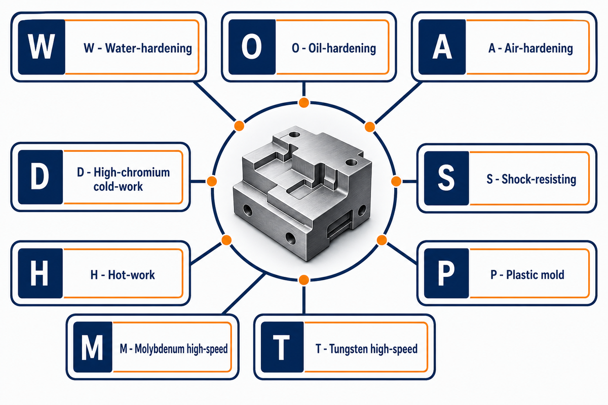
Nine AISI letter series give readers a useful first map: W, O, A, D, S, H, P, M, and T. They suggest broad design priorities, but they do not prove exact chemistry, product form, supplied condition, hardness, equivalence to another standard, or suitability for a part. Always resolve the actual grade and specification.
This nine-series map is not the same as ISO 4957. The current ISO 4957:2018 catalogue groups tool steels into four broad categories and was confirmed in 2023. ASTM A681-24 separately covers available wrought alloy tool-steel products and says selection depends on design, service conditions, and desired properties. These standards boundaries are more important than forcing unlike classification systems into a one-to-one table.[ISO scope]
| AISI series / class | Common family emphasis | Machining question to resolve |
|---|---|---|
| W | Water-hardening, relatively simple carbon tool steels | What distortion and quench-risk controls follow the feature geometry? |
| O | Oil-hardening cold-work grades, including O1 tool steel | Which features are roughed before hardening and finished afterward? |
| A | Air-hardening cold-work grades such as A2 tool steel | Does the actual section size and condition support the planned sequence? |
| D | High-carbon, high-chromium cold-work grades such as D2 tool steel | How will abrasive wear, burr control, and finish be balanced? |
| S | Shock-resisting grades such as S7 tool steel | Are interrupted cuts and edge loading controlled by a rigid setup? |
| H | Hot-work grades used where hot strength matters | Is thermal cycling more critical than room-temperature hardness? |
| P | Plastic mold grades, often supplied prehardened | Is the stock annealed, prehardened, welded, or locally altered? |
| M | Molybdenum high-speed steel | What carbide and hot-hardness effects control tool life? |
| T | Tungsten high-speed steel | Which operation and finishing route can hold the required edge geometry? |
Treat the table as a reading aid, not a purchasing specification. For example, a “D2” callout still needs the applicable standard, product form, delivery condition, heat-treatment state, hardness evidence, and traceability requirements. “A2” and “A3” aren’t interchangeable merely because both begin with A.
Search shorthand such as tool steel D2, tool steel A2, or tool steel O1 still needs the grade-condition record behind it. Cold-work tool steels may prioritize good toughness, high hardness, or abrasion resistance in different proportions. Hot-work tool steel used for extrusion dies or other hot-work applications must address behavior at high temperatures. M and T grades belong to high-speed cutting tools and dies, not to a universal “faster machining” class. For broader navigation across other material families, use Zhenling’s materials hub; it does not replace a grade-specific standard.
Annealed, Prehardened, or Hardened: Choose the Machining Sequence
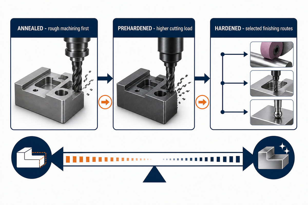
The supplied and target condition determine the process sequence. Annealed stock may permit most rough machining before heat treatment. Prehardened mold steel may reduce later distortion steps but raises cutting load. Hardened material may require hard milling, grinding, or wire cutting for selected features. None of these routes is automatically superior.[ISO scope]
One useful route separates material removal from final restoration. Rough the stable, accessible volume first; preserve datums and finishing stock where movement is expected; perform the specified thermal steps; then restore critical form, surface finish, and size with an operation suited to the final condition. Stress relief belongs in the plan only when the material, geometry, and heat-treatment authority support it.
Weigh the advantages of machining more material before hardening against movement and rework risk. Phrases such as “excellent dimensional stability,” “toughness and excellent dimensional stability,” or “stability during heat treatment” aren’t allowance data. They need a grade, section, thermal route, geometry, and measurement result.
ASM’s distortion guidance identifies design, composition, initial condition, machining procedure, and heat treatment as interacting factors. It also notes that distortion may occur during and after heat treatment. That evidence rules out a universal stock allowance. It does not supply a replacement number.
The 3-Layer Grade–Condition–Geometry Map
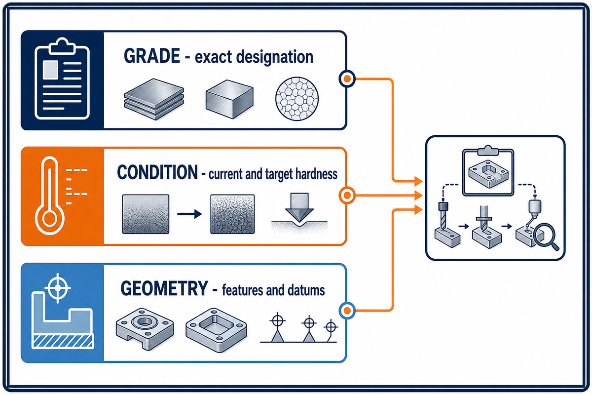
This 3-Layer Grade–Condition–Geometry Map is a planning method, not a published standard. Layer 1 establishes material identity. Layer 2 fixes the current and target metallurgical condition. Layer 3 describes the features that must be created and verified. Choose a process route only after all three layers agree.
- For the first layer, record the grade: exact designation, governing specification, product form, chemistry or certification needs, and any approved substitutions.[ISO scope]
- For the second layer, record the condition: annealed, prehardened, normalized, quenched and tempered, case condition if relevant, current hardness, target hardness, and thermal history.
- Geometry layer: stock shape, thin walls, deep pockets, small holes, interrupted surfaces, corners, reach, datum structure, and the features tied to service loading.
Consider a D2 insert with a deep pocket and a narrow wall. Its family label suggests wear-oriented cold-work steel, but it does not decide whether the wall should be finished before or after hardening. That decision also needs current hardness, target hardness, wall stiffness, heat-treatment movement, corner radius, workholding access, and how the wall will be inspected.
This map applies across machining techniques and steel components. It keeps machined parts tied to their material state and functional geometry instead of reducing the route to a machine name.
CNC Milling and Turning Tool Steel: Rigidity, Engagement, and Heat
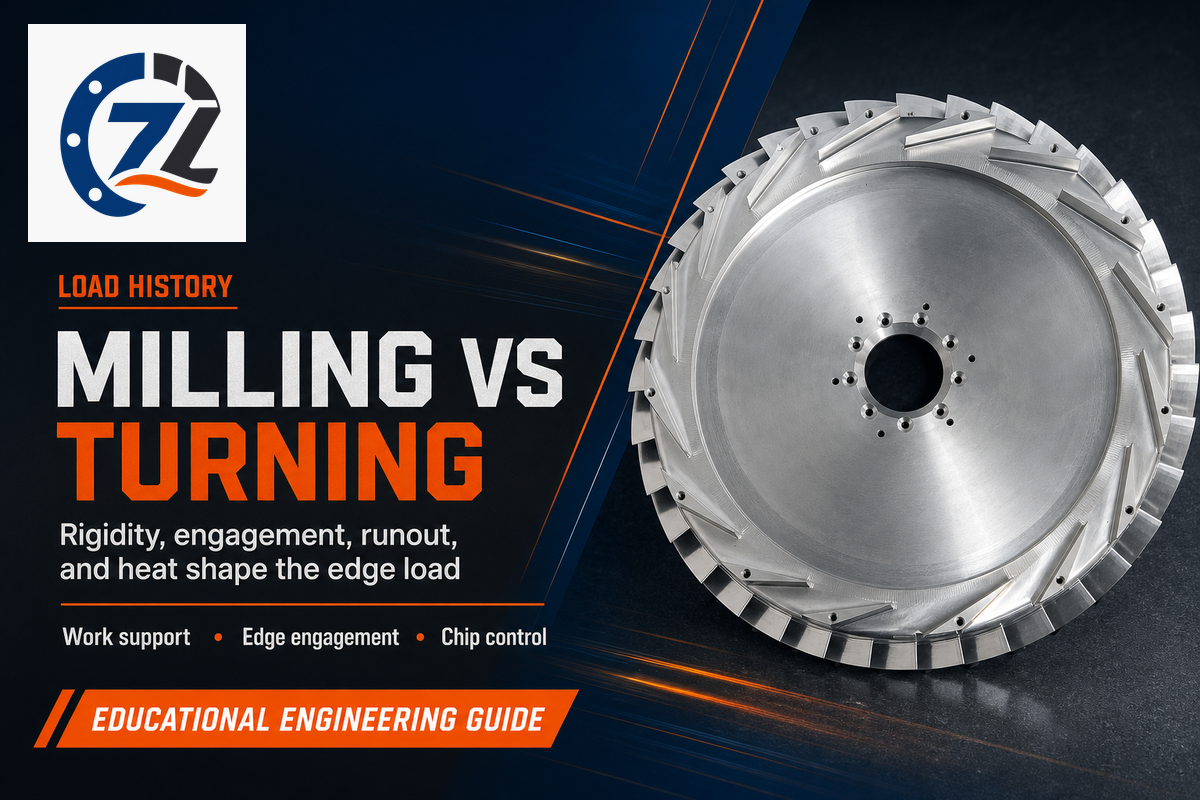
CNC milling and turning do not expose the cutting tool to the same load history. Turning can provide continuous engagement, while milling repeatedly enters and exits the work material. Interrupted features, scale, runout, long reach, thin sections, or weak workholding can turn either operation into a shock and heat-management problem.
For milling machines, radial and axial engagement, cutter diameter, tooth count, toolpath, overhang, and chip evacuation shape the load on each edge. For turning, nose geometry, depth of cut, feed, work support, interrupted surfaces, and chip control change the contact. Without those conditions, a speed value isn’t transferable evidence.
A peer-reviewed H13 study reported up to 50% lower tool wear for turn-milling than conventional turning within its tested setup. Surface-roughness behavior remained operation-specific. That is a useful case for considering a different kinematic route, but it is not a promise that turn-milling will improve every H13 part.[H13 study]
Metalworking-fluid boundary: Coolant is also an exposure-control subject. OSHA advises using the supplier Safety Data Sheet, maintaining the fluid, limiting mist and splash, and providing suitable exhaust or local ventilation. This guide cannot replace a site-specific safety assessment.
Cutting Tools and Wear Modes for Hardened Tool Steel
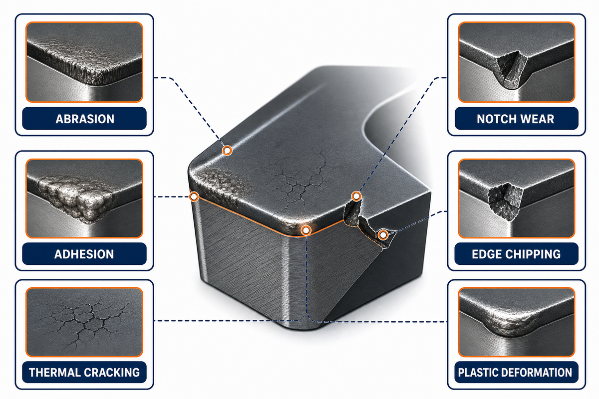
Cutting tools for hardened tool steel should be selected against the expected wear mechanism and required outcome. Abrasion, adhesion, thermal cracking, notch wear, edge chipping, and plastic deformation do not call for the same first response. Carbide, ceramic, and cubic boron nitride options also have different stability and interruption requirements.
Begin with the operation and failure mode. Uniform flank wear may support a controlled tool-life study. Edge chipping points first toward interruption, runout, engagement, impact, or inadequate edge strength. Built-up material suggests a different contact and temperature condition. Burr problems may require edge-geometry or support changes even when wear remains acceptable.
Hardness stays in the decision, but it does not own the decision. The D2 experiment cited earlier found one tool leading on wear and cost while another reduced burr height. Toolmaker guidance likewise warns that tool steels at similar Rockwell hardness can machine differently because composition and adhesion behavior differ. Commercial guidance is useful for a starting window; a controlled trial on the real setup still carries the proof.[D2 study]
Hard Milling, Grinding, or Wire EDM After Heat Treatment
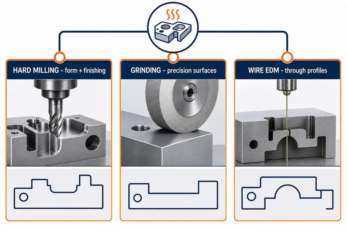
After heat treatment, choose hard milling, grinding, or wire electrical discharge machining by feature and verification need. Hard milling can combine form generation and finishing on a rigid, repeatable system. Grinding suits many precision surfaces but introduces its own thermal and subsurface risks. Wire cutting reaches through-features yet can leave a thermally affected or recast layer.[D2 study]
| Route | Strong fit | Boundary to verify |
|---|---|---|
| Hard milling | Accessible three-dimensional form on a rigid, thermally stable system | Runout, reach, toolpath, corner radius, chatter, and surface integrity |
| Grinding | Precision faces, diameters, and established finishing features | Burn, residual stress, cracks, wheel condition, dressing, and thermal control |
| Wire EDM | Through profiles, narrow slots, and hard material with low cutting force | Recast layer, corner behavior, skim strategy, start holes, and recast-sensitive service |
A reported fine-blanking case moved selected 62–64 HRC die components from EDM and hand grinding to hard milling only after repeatability, rigidity, thermal consistency, runout, probing, coolant delivery, and modular workholding were engineered together. The case supports systems thinking, not a blanket replacement rule.
Service loading must also be explicit. A visually smooth surface is not proof that a fatigue-critical, crack-sensitive, recast-sensitive, or residual-stress-sensitive feature is acceptable. When those risks matter, the drawing or quality plan needs a suitable verification method and acceptance rule.
Plan for Distortion, Stock Allowance, Surface Integrity, and Measurement
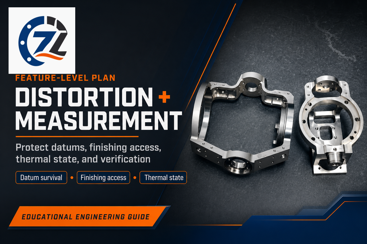
Distortion and finishing stock must be planned together, but no universal allowance is defensible. Section size, asymmetry, prior cold work, removal sequence, residual stress, support during machining, heat-treatment fixtures, quench route, tempering, and final feature relationships can all move the result.
Use a feature-level plan. Identify the datums that must survive each setup, the surfaces that establish later workholding, and the dimensions most sensitive to thermal or stress movement. Reserve stock only where the planned finishing operation can reach it and where later removal will not release a new imbalance. Large blanket allowances may add heat and time without protecting the critical geometry.
Measurement conditions belong in the same plan. A 2023 NIST report states that ISO 1:2022 specifies 20 °C as the standard reference temperature for geometrical product specification and verification. That does not mean every part instantly reaches that temperature. Machine warm-up, workpiece thermal state, fixture influence, instrument capability, sampling, datum realization, and measurement uncertainty still need to be stated.NIST report
4 Heat–Wear Observation Checks Before You Change the Process
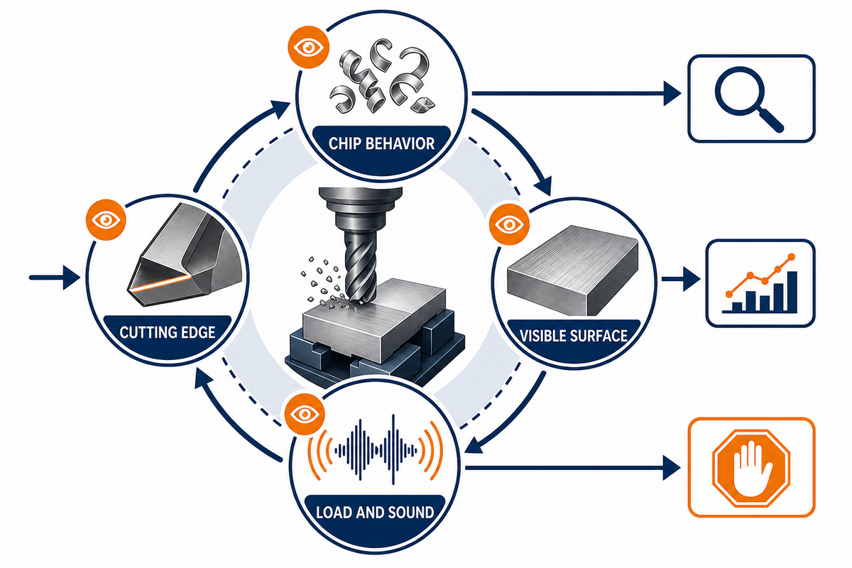
Four observation checks can guide the next measurement: chip behavior, cutting edge condition, visible surface evidence, and machine load or sound. They are not a diagnostic system. Their purpose is to prevent random parameter changes and identify when to inspect, measure, review the setup, or stop the process.
- Chip behavior: Note evacuation, recutting, nesting, color changes, and sudden shifts. Chip color alone cannot determine material temperature because geometry, speed, engagement, and oxidation affect it.
- Cutting edge: Separate gradual flank wear from chipping, notch wear, built-up material, coating loss, or catastrophic damage. Photograph or measure at controlled intervals.[D2 study]
- Visible surface: Check texture change, smearing, burrs, tearing, chatter marks, and unexpected color. Even a good surface finish does not rule out white layer, residual stress, microcracking, or metallurgical change.
- Load and sound: Compare spindle load, torque, vibration, or sound with a known stable baseline. Abrupt change can trigger a controlled stop, but machine-specific noise and control filtering limit interpretation.
Instrumented monitoring can go much further. For example, US12269137B2 describes force, vibration, strain, acoustic, torque, infrared, and thermal signals processed with machine-learning methods. The patent is assigned to Kennametal Inc.; it is third-party landscape evidence and is not Zhenling technology or proof that manual observation can diagnose wear.
When Engineering Guidance Becomes Drawing-Specific
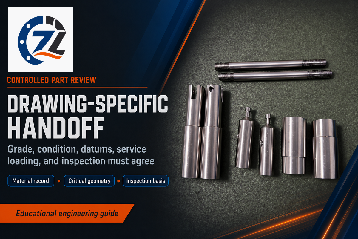
General guidance ends when the route depends on an unresolved drawing input. Exact grade, governing standard, supplied hardness, target heat treatment, datums, thin or interrupted features, service loading, critical surfaces, inspection method, and acceptance criteria all change the answer. At that point, advice must become a controlled part review.
A useful handoff package states the material and condition, identifies critical-to-function features, marks pre- and post-treatment dimensions, defines datum relationships, names the required surface or subsurface checks, and records any approved process restrictions. It should also state measurement temperature, sampling expectations, and uncertainty where they affect acceptance.
| Drawing input | Reference scope | Record before review |
|---|---|---|
| Designation | Governing standard | Exact grade and applicable edition |
| Product form | Material record | Bar, plate, block, or supplied blank |
| Supplied condition | Delivery record | Annealed, prehardened, or other stated condition |
| Current hardness | Test record | Scale, method, and measurement location |
| Target condition | Drawing or heat-treatment authority | Required hardness and approved thermal route |
| Critical geometry | Drawing | Datums, thin walls, pockets, and interruptions |
| Service loading | Design authority | Loaded surfaces and integrity-sensitive features |
| Finishing route | Process plan | Pre- and post-treatment operations |
| Inspection basis | Drawing or quality plan | Method, sampling, temperature, and uncertainty |
This is the one point where the educational guide hands off to a commercial service page. If you have a specific drawing, hardness state, and inspection requirement, Zhenling’s tool steel CNC machining service page explains its drawing-review and quotation path. That link is for part-specific evaluation; it does not turn the guide into an RFQ or supplier-selection article.
The governing decision
Do not ask which tool steel is “easy” in isolation. Ask which grade, condition, geometry, operation, service risk, and measurement plan must work together. That question produces a defensible machining route and a clear point for drawing-specific review.
Frequently Asked Questions
Is tool steel hard to machine?
Tool steel can be demanding, but its machinability depends more on grade, condition, hardness, geometry, and setup than on the family name alone under controlled conditions.
Annealed stock may machine with conventional cutting tools, while prehardened or hardened stock narrows the stable window and raises the importance of rigidity, runout, engagement, edge preparation, and thermal control. Abrasive carbide populations, interruption, thin walls, or long reach can be as important as hardness. Use a grade- and operation-specific starting point, then verify it on the real setup.
What is the difference between 4140 and tool steel?
AISI 4140 is a chromium-molybdenum alloy steel, while tool steels are families developed around tool, die, mold, wear, shock, or hot-hardness duties under different material standards.SAE standard
Those categories overlap in some property goals, but they are not interchangeable labels. Results from 4140 should not be used as direct proof for D2, A2, H13, O1, or S7 tool steel. Comparison still depends on the governing specification, heat-treatment state, hardness, product form, and service requirement. Equal hardness does not erase chemistry, microstructure, inclusion, carbide, toughness, or tempering differences. Treat 4140 evidence as 4140 evidence unless a qualified material authority and the drawing establish a valid substitution. Any proposed replacement must also preserve the required hardenability, fatigue response, wear behavior, section response, and inspection basis. Machining tests can show whether a setup cuts a coupon; they cannot by themselves establish that the substitute will perform the same function in service.
What is the best tool steel for machining?
No tool steel is best for machining without a required function, hardness state, geometry, production route, and acceptance plan for a specific part and duty.
Grades that cut readily in an annealed state may not meet wear, shock, hot-work, dimensional-stability, corrosion-resistance, or service-life needs. Start from the part’s function and governing material requirements, then decide which features can be produced before heat treatment and which must be restored afterward. Machinability is one selection input, not the whole specification.
Can you CNC machine steel?
Yes, CNC machines can cut many steel materials, including tool steel, when the machine, tool, setup, and process match the material condition for the intended feature.
Ask whether the specific CNC machine has enough rigidity, spindle behavior, workholding support, tool access, coolant or chip control, and measurement capability for the feature and hardness involved. Turning, drilling, CNC milling, hard milling, grinding, and wire cutting each solve different parts of the process chain.
References & Sources
- ASTM A681-24: Standard Specification for Tool Steels Alloy ASTM International
- SAE AMS6395K: SAE 4140 Aircraft-Quality Steel SAE International, 2025
- ISO 4957:2018 Tool Steels International Organization for Standardization
- Control of Distortion in Tool Steels ASM International
- High-Speed Turn-Milling of H13 Tool Steel Lubricants, 2025
- Cutting-Tool Comparison for AISI D2 at 60 HRC The International Journal of Advanced Manufacturing Technology, 2026
- Metalworking Fluids: Evaluating Exposure Occupational Safety and Health Administration
- NIST IR 8470: Test Temperature Range for NIST Certified Charpy Specimens National Institute of Standards and Technology, 2023
- Hard Milling Replaces Hand Grinding in Finishing Die Components Modern Machine Shop
- US12269137B2 Tool-Wear Monitoring Patent Assigned to Kennametal Inc.
Why This Guide Draws a Hard Boundary
Shanghai Zhenling manufactures non-standard metal components from customer drawings and samples. This guide turns recurring material-condition, heat-treatment, geometry, and inspection questions into an educational decision path; it does not claim a universal parameter, guaranteed result, or independently verified tool-steel case. The company context was supplied for this project; the technical claims are attributed to the listed third-party sources.
![Shop-Floor Carbon Steel CNC Machining Guide [2026]](https://zhenlingmetal.com/wp-content/uploads/2026/08/carbon-steel-cnc-machining-handbook-r2-featured-150x150.png)