Get in touch with Zhenling Company


Updated August 2026
CNC Milling vs Turning is best understood from the drawing, not from a preference for one machine. Start with the feature that controls function, trace its datum relationship, then document setup transfer, inspection evidence, quantity, and secondary operations. That sequence produces an input brief a supplier can use to explain a route and a buyer can audit.
Quick Drawing Input Check
| Dominant geometry | Rotational, prismatic, or mixed |
|---|---|
| Controlling relationship | Diameter/runout, flat/position, or cross-operation datum |
| Commercial denominator | Accepted parts, not machine hours alone |
| Proof required | Feature-specific inspection method and document scope |
CNC milling vs turning has no universal winner. Turning naturally controls rotational features because the workpiece spins; milling naturally controls flats, pockets, slots, and multi-face features because the cutter moves around a fixtured part. Mixed geometry may need both, but datum and inspection risk decide whether one setup is actually better.
What matters before the machine label
- Fewer setups don’t automatically mean a shorter cycle or a lower accepted-part cost.
- A nominal machine accuracy figure doesn’t prove the tolerance of a finished component.
- Quantity changes how heavily programming, fixtures, jaws, and setup weigh on each accepted part.
- A process-neutral request for quotation lets capable suppliers propose a safer route.
1. CNC Milling vs Turning at a Glance
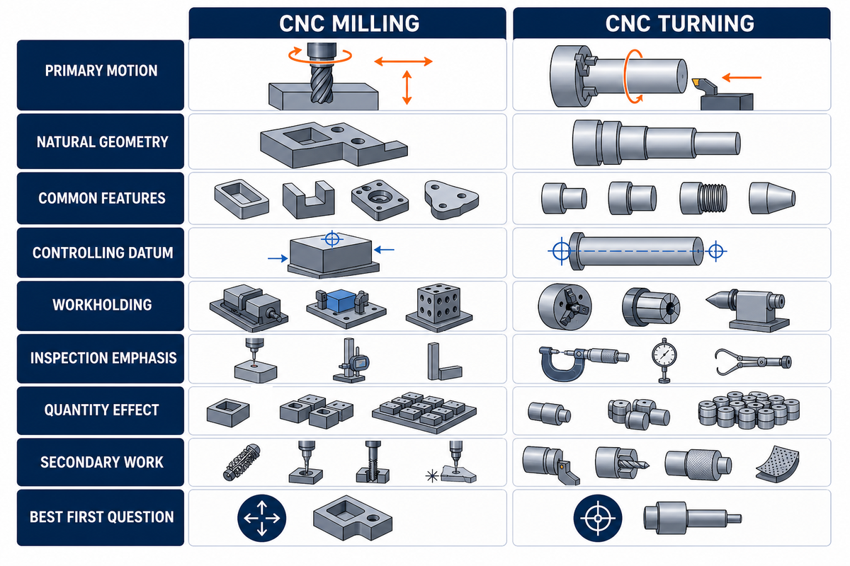
CNC turning rotates the workpiece against a cutting tool, while CNC milling rotates a cutter around a stationary or indexed workpiece. Turning provides the natural motion model for rotational features; milling provides it for prismatic and multi-face features. Neither motion model replaces a drawing and datum review.
In modern manufacturing, the types of CNC machining belong to one CNC machining process family, yet each manufacturing process assigns motion and datum control differently. CNC equipment selection can therefore begin with the drawing rather than with a preferred lathe machine.
Kinematics define the main difference between CNC milling and CNC turning; they don’t promise cost or precision. CNC lathes tend to make diameters, bores, shoulders, grooves, tapers, and coaxial threads efficiently. CNC milling machines tend to make faces, pockets, slots, profiles, hole patterns, and off-axis features. Modern turning centers and multi-axis milling machines blur that boundary, but they don’t erase it.
NIST’s machine-tool calibration review reinforces the boundary: a motion or axis description does not by itself establish finished-part capability.
Equivalent searches include CNC turning vs milling, CNC milling vs CNC turning, and CNC turning vs CNC milling. Broader comparisons such as milling vs turning vs grinding or turning vs milling vs drilling add processes outside this guide. A CNC milling and turning machine appears here only when mixed features make its route relevant.
| Comparison factor | CNC milling | CNC turning | Limitations / not suitable for |
|---|---|---|---|
| Primary motion | Rotating multi-edge cutter | Rotating workpiece | Motion alone does not select the full route |
| Natural geometry | Prismatic, planar, irregular, multi-face | Cylindrical, conical, coaxial | Mixed features can reverse the first screen |
| Common features | Pockets, slots, flats, hole patterns | Diameters, bores, grooves, threads | Tool access and interruption still apply |
| Controlling datum | Faces, planes, hole patterns | Axis, diameter, centerline | Cross-operation datums add transfer risk |
| Workholding | Vise, fixture, soft jaws, vacuum or custom support | Chuck, collet, centers, soft jaws | Thin or interrupted features can distort |
| Inspection emphasis | Position, flatness, profile, multi-face relation | Diameter, runout, cylindricity, coaxiality | Measurement strategy remains feature-specific |
| Quantity effect | Fixture and programming weight changes by lot | Jaw, bar, and handling assumptions change by lot | No universal break-even quantity |
| Secondary work | May need turning for efficient coaxial features | May need milling for flats and off-axis holes | Re-clamping can move the datum chain |
| Best first question | Which face or feature controls function? | Which axis or diameter controls function? | Supplier review is needed when both answers matter |
Record on the drawing
- Identify the feature that controls function
- Name its locating datum
- Mark every cross-operation relationship
- Define the acceptance evidence
Do not infer from shape
- Do not prescribe a machine from the blank
- Do not equate one setup with no transfer risk
- Do not convert axis accuracy into part tolerance
- Do not compare unmatched quotation scopes
Boundary: a shaft with an off-axis cross-hole, or a housing with a critical turned bore, can need both process families. Article scope covers inputs and failure boundaries; Zhenling’s interactive tools retain the actual route-screening role.
2. How Cutting Motion Changes Geometry and Datum Control
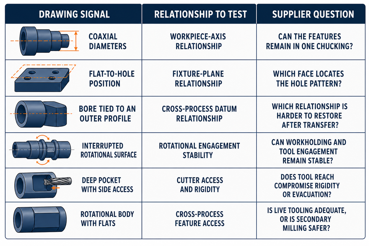
Cutting motion determines which geometry stays naturally centered, which faces require indexing, and where clamping force enters the part. A turning spindle carries the work around an axis; a milling spindle carries the cutter through programmed axes. The useful question is which motion preserves the drawing’s controlling relationship with fewer transfers.
Toolpath review should identify whether a milling cutter performs face milling, thread milling, or other milling operations, and whether rotating cutting changes access to the controlling feature. CNC machining technology helps execute that plan, but it does not choose the datum for the buyer.
Computer numerical control coordinates both types of CNC machines, but it doesn’t make their mechanical responsibilities identical. On a CNC turning machine, the spindle establishes the rotational axis while the stationary cutting tool advances along or across it. On a CNC mill, the cutter rotates and the fixture establishes the workpiece location while linear or rotary axes create the tool path.
Across the manufacturing industry, both methods remove material to create the desired shape. Part design determines which motion keeps the functional geometry tied to the simplest datum and inspection chain.
Treat CNC turning and milling as route families within one machining process review, then test each family against the same drawing and acceptance scope.
One 2026 peer-reviewed turn-milling experiment warns against simple performance claims. Its results belong to the named 6061-T6 workpiece, tool geometry, speeds, depth, fluid condition, and surface objective; its reported model errors stayed within 10% for that setup. Here, the research defines a transfer rule: measured performance travels with its conditions, not with the words “milling” or “turning.”
| Drawing signal | Motion relationship to test | Question before release |
|---|---|---|
| Coaxial diameters | Workpiece-axis relationship | Can the features remain in one chucking? |
| Flat-to-hole position | Fixture-plane relationship | Which face locates the hole pattern? |
| Bore tied to an outer profile | Cross-process datum relationship | Which relationship is harder to restore after transfer? |
| Interrupted rotational surface | Rotational engagement stability | Can workholding and tool engagement remain stable? |
| Deep pocket with side access | Cutter access and rigidity | Does tool reach compromise rigidity or evacuation? |
| Rotational body with flats | Cross-process feature access | Is live tooling adequate, or is secondary milling safer? |
Common mistake: treating a CAD model as a collection of shapes without reading its datum feature symbols and inspection notes. Two visually similar cylindrical components can need different machining methods when one controls runout from the centerline and the other controls hole position from a milled face.
3. Document the Dominant Geometry and Datum Chain
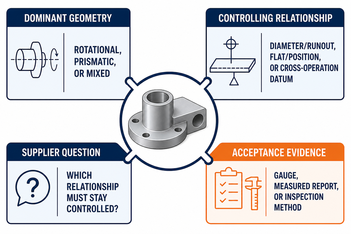
Dominant geometry is only an initial drawing classification. Record whether functional relationships remain rotational, depend on faces or multi-face positions, or cross the turning-to-milling boundary. The datum chain and required acceptance evidence then give a supplier enough information to propose and justify the manufacturing sequence.
Choosing the right process means more than choosing between CNC milling and turning by shape. Symmetrical parts can contain off-axis controls, while complex components may retain a rotational datum. The same logic applies across a range of materials and the production of complex feature combinations.
Feature–Datum–Evidence Drawing Brief: An 8-Factor Input Framework
The Feature–Datum–Evidence Drawing Brief connects each critical feature to its locating reference, supplier question, and required acceptance proof.
Use the brief on the controlled drawing before asking for a machine type. It prevents a familiar procurement error: a buyer sees a round blank, prescribes turning, and only later discovers that a milled face and an off-axis hole control assembly. The supplier remains responsible for proposing and explaining the manufacturing sequence while the buyer retains control of function and acceptance.
NIST’s 21-production-part comparison shows why modeled machine uncertainty and measured part errors remain distinct evidence layers; the Drawing Brief keeps that acceptance handoff visible.
| Feature input | Supplier question | Datum question | Acceptance evidence | Limitations / not suitable for |
|---|---|---|---|---|
| Outer diameter + shoulder | Can one chucking keep these coaxial? | Common centerline? | Diameter and runout record | Review interrupted or thin walls |
| Coaxial bore + thread | Can the bore and thread share one reference? | Same chucking? | Bore size, thread gauge, runout | Blind access can limit tooling |
| Flat + pocket | Which plane locates both features? | Which plane locates depth? | Flatness, depth, profile | Deep reach can reduce rigidity |
| Multi-face hole pattern | How is the shared origin preserved after indexing? | Shared origin after indexing? | Position report from defined datums | Indexing access must be proven |
| Shaft + keyway | How is the keyway clocked to the shaft datum? | Keyway clocked to what? | Runout plus keyway position | Transfer can lose angular reference |
| Flange + bolt circle | How are face, axis, and hole pattern related? | Face and axis relationship? | Face runout and hole position | Second setup can stack error |
| Eccentric bore | Which datum defines the offset? | Offset from axis or face? | Offset and bore geometry | Machine architecture matters |
| Thin cylindrical sleeve | How is free-state distortion controlled? | Free-state or restrained? | Diameter under defined condition | Clamping distortion can dominate |
| Thin plate with bores | How is release-state flatness verified? | Support and release state? | Flatness and bore position | Fixture release can change shape |
| Rotational body + off-axis ports | Which datum controls port angle and position? | Ports tied to axis or face? | Runout, angle, and position | Live-tool access must be demonstrated |
- Circle the functional features — identify the dimensions that affect fit, motion, sealing, or assembly.
- Trace each controlling datum — note whether the relationship stays within one rotational or prismatic setup.
- Assign acceptance evidence — define the gauge, report, or inspection method needed for each feature.
- Let the supplier propose the sequence — request the assumed setup count and transfer plan without dictating an unsafe machine route.
Can a CNC Mill Replace a Lathe?
CNC mills can produce some circular features by interpolation or rotary-axis work, but they don’t replace a lathe for every part. Turning keeps rotational geometry tied to the spindle axis, which can simplify diameter and coaxial-feature control. Milling may suit a mainly prismatic part with limited round features. Route decisions should compare access, workholding, stock, quantity, inspection, and supplier evidence.
Scenario: consider a compact valve body that looks cylindrical in the three-dimensional model. Its sealing bore is concentric with the outer diameter, but two ports are positioned from a machined mounting face. A turning-only instruction protects the bore relationship yet leaves the port-to-face requirement for a transfer. A milling-only instruction may make the ports convenient while making the concentric bore less natural. Marking the bore, face, ports, and their acceptance evidence shows why the supplier must explain any mixed-process datum-transfer plan.
4. Compare Setup, Workholding, and Tool Access
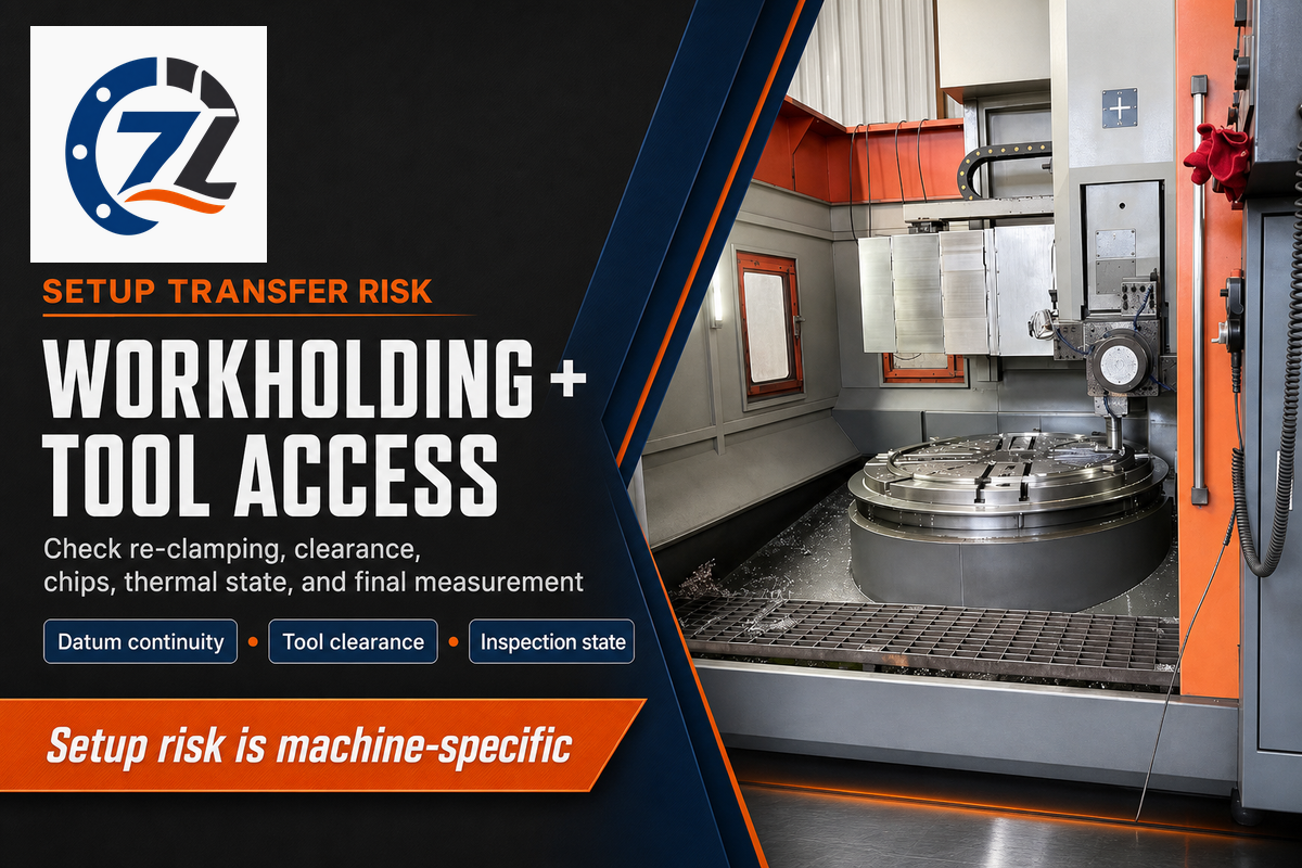
Setup risk grows when a critical feature must be re-clamped, indexed, reached with a long tool, or cleared during tool changes. Milling often carries fixture and access questions; turning often carries chucking, runout, and interrupted-cut questions. The safer route is the one that preserves critical datums through those events.
Peer-reviewed five-axis research found that changing the setup position for the same programmed part reduced axial movement by 16.76% and machining time by 10.70% in that exact case. Those percentages aren’t general milling savings. They demonstrate something more useful: setup orientation can change axis travel, overtravel risk, interference, and time even when the part and toolpath appear fixed.
One Boeing-NIST tool-change paper models 8 states or movements and distinguishes machines that only need to clear the workholding setup from machines that return to a reference position. That makes tool-change clearance a route input, not a detail to check after programming.
Setup Transfer Risk Budget: A 9-Event Risk Map
The Setup Transfer Risk Budget lists every event that can move a datum, block a tool, change the thermal state, or alter acceptance evidence.
| Risk event | Evidence to request | Failure signal | Limitations / not suitable for |
|---|---|---|---|
| Initial location | Datum and contact plan | Ambiguous locating surface | Do not score without the controlled drawing |
| Clamp load | Jaw or fixture concept | Thin-wall or free-state distortion | Generic clamping claims are insufficient |
| Tool reach | Tool and holder envelope | Long reach or holder collision | Access does not prove rigidity |
| Tool change | Clearance or reference behavior | Fixture blocks safe movement | Machine-specific verification required |
| Chip evacuation | Orientation and evacuation plan | Chip recutting or packed cavity | Material and feature depth change the risk |
| Part transfer | Transfer datum and locating repeatability | Critical relation crosses setups | One-machine branding is not proof |
| Thermal change | Warm-up and inspection condition | Drift between cut and measurement | Needs feature-specific tolerance context |
| Deburr or finish | Post-process sequence | Acceptance surface changes later | Do not close inspection too early |
| Final measurement | Method, sampling, and report scope | Quote excludes needed evidence | No generic severity score transfers |
What Are the Downsides of CNC Milling?
CNC milling can require more elaborate fixturing, multiple indexed orientations, and long-reach tools when features sit on several faces or deep inside a part. Those conditions can add setup time, tool deflection, collision constraints, and chip-evacuation problems. Milling is still the correct route for many complex geometries; the downside appears when a buyer assumes that cutter access also proves rigidity, datum continuity, or acceptance capability.
Shop-floor symptom to investigate: special fixtures can consume more planning and setup effort than the cut on a small lot. Ask suppliers to separate reusable fixture assumptions from one-time work, and ask whether the quote relies on soft jaws, a dedicated fixture, or a general-purpose vise setup.
5. Plan Tolerance, Surface Finish, and Inspection
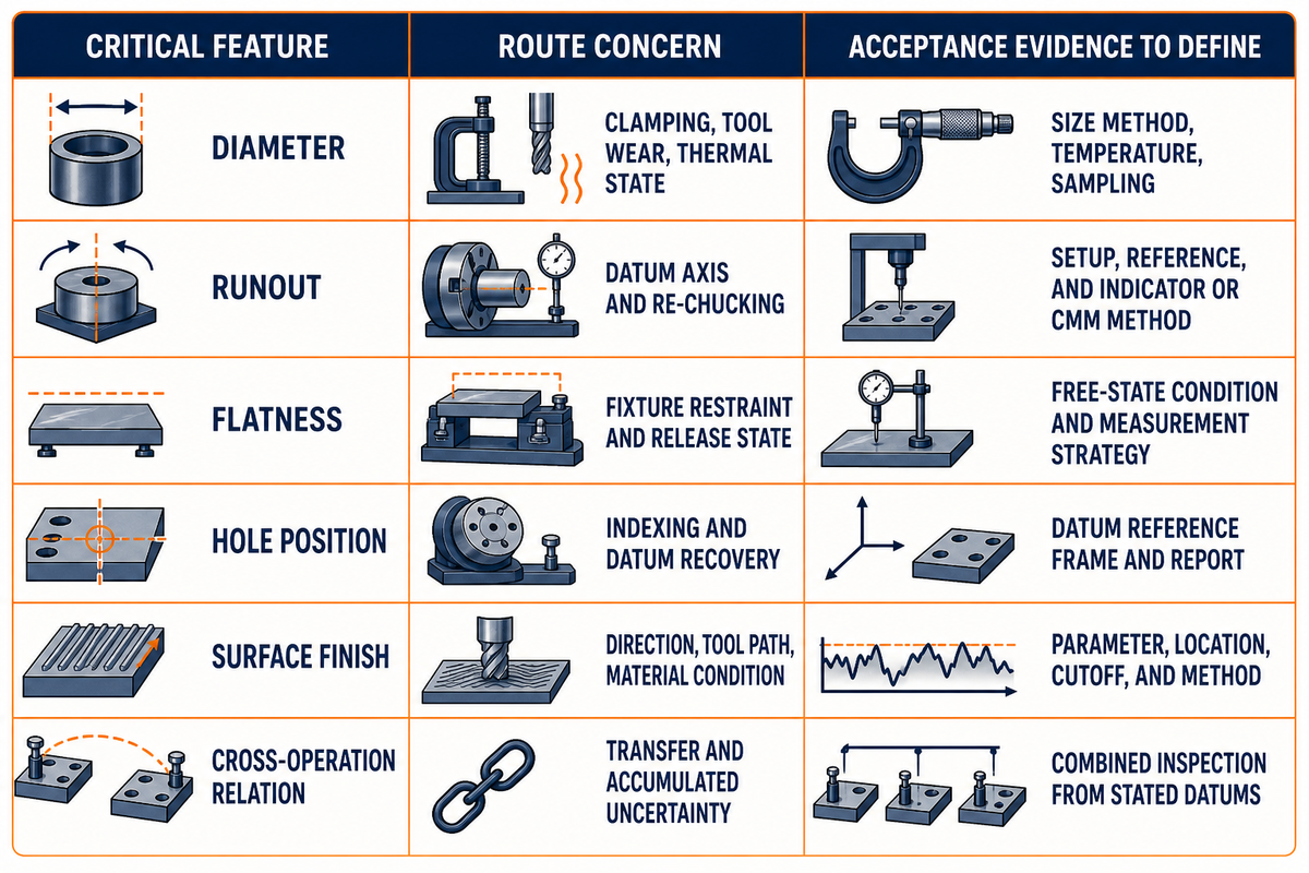
Neither CNC milling nor CNC turning is universally more accurate. Finished-part conformity depends on the critical feature, machine error, workholding, cutting state, material response, setup count, thermal condition, and measurement method. Compare the evidence needed for each feature rather than assigning one process a blanket tolerance advantage.
NIST’s machine-tool calibration review distinguishes intra-axis, inter-axis, load, thermal, and volumetric effects. That’s why a positioning specification can’t be copied directly into a finished-part promise. Process state, clamping, tooling, and measurement remain between machine motion and accepted geometry.
In separate work, NIST compared modeled uncertainty with measured errors from 21 production parts. The value for a buyer is the evidence architecture: machine-level uncertainty and actual part errors are related, but they aren’t interchangeable.
ISO 230-2:2014, reviewed and confirmed in 2025, addresses positioning accuracy and repeatability of individual numerically controlled axes. It does not certify the tolerance of a buyer’s part. Likewise, ISO 10791-2:2023 covers geometric tests for vertical-spindle machining centres, not every process and acceptance condition in a quotation.
Research in a 2026 NIST-listed thermal-deformation study reports that loads from motors, part processing, and ambient change can dominate volumetric error in the studied context. Its in-process measurement-to-compensation cycle took less than 100 seconds, and its experiments reduced errors by up to an order of magnitude. Those results describe the authors’ method, not ordinary supplier capability. Buyer action is simpler: define the measurement condition and ask how thermal state is controlled for critical features.
Keep the evidence envelopes separate: 16.76% axial movement and 10.70% machining time belong to the setup-position study, while 100 seconds belongs to the thermal-compensation experiment. The 100 seconds value is not a supplier cycle-time promise.
| Critical feature | Route concern | Acceptance evidence to define |
|---|---|---|
| Diameter | Clamping, tool wear, thermal state | Size method, temperature, sampling |
| Runout | Datum axis and re-chucking | Setup, reference, and indicator or CMM method |
| Flatness | Fixture restraint and release state | Free-state condition and measurement strategy |
| Hole position | Indexing and datum recovery | Datum reference frame and report |
| Surface finish | Direction, tool path, material condition | Parameter, location, cutoff, and method |
| Cross-operation relation | Transfer and accumulated uncertainty | Combined inspection from stated datums |
Common mistake: requesting “tight tolerance” without identifying the feature, datum, free-state condition, or report. A turning service and a milling service can both meet demanding drawings, but the quotation must state what will be measured and how acceptance will be decided.
6. Compare Accepted-Part Cost, Not an Hourly Rate
Accepted-part cost compares the complete route: programming, setup, fixtures or jaws, stock, cycle time, secondary operations, inspection, rework, and reject exposure. Turning can be economical for suitable cylindrical parts, but no public hourly rate or fixed saving percentage can replace a condition-matched quotation for the same drawing and quantity.
Public rates do exist. For example, Texas State University publishes machine-specific external rates for a defined makerspace. That doesn’t create a commercial market benchmark because the facility scope, user class, included labor, setup, quality documentation, and risk allocation differ from supplier quotations. A real machine-hour number can still answer the wrong question.
Peer-reviewed manufacturing cost research treats process, part size, material, features, setup, handling, and production conditions as interacting drivers. Quantity matters because one-time programming and setup are spread across a different number of accepted components. Don’t ask for a universal break-even volume; ask each supplier to state the assumed batch pattern and reusable tooling.
Quote-normalization equation
Accepted-part cost = (programming + setup + fixtures or jaws + lot processing + secondary work + inspection + expected rework) ÷ accepted quantity. Use supplier inputs; don’t insert a generic market rate.
Fictional drawing setup: the following values exist only to demonstrate how a buyer can keep two route proposals on the same basis. They don’t describe a Zhenling part, a normal tolerance, or a recommended process window.
| Input type | Illustrative value | Use in the review |
|---|---|---|
| Stock diameter | 42 mm | Stock and removal basis |
| Finished diameter | 38 mm | Rotational feature |
| Overall length | 80 mm | Workholding envelope |
| Flange thickness | 8 mm | Face relationship |
| Flat width | 24 mm | Milled feature |
| Port diameter | 6 mm | Off-axis access |
| Shoulder length | 18 mm | Turning sequence |
| Groove width | 3 mm | Tool access |
| Runout tolerance | 0.05 mm | Axis-based acceptance |
| Port position tolerance | 0.10 mm | Cross-operation relation |
| Flatness tolerance | 0.08 mm | Fixture-release check |
| Surface requirement | 1.6 μm Ra | Measurement scope |
| Report temperature | 20 °C | Measurement condition |
| Route A setup | 4.0 hr | One-time lot input |
| Route B setup | 1.5 hr | One-time lot input |
For the same fictional worksheet, one inspection plan could record the part at 20 °C, repeat it at 22 °C, allow 30 min before measurement, and use a 15 min recheck interval. It would keep the 0.05 mm runout, 0.10 mm position, 1.6 μm Ra finish, and 80 mm length tied to named methods rather than treating them as machine-label claims. The training sheet could also list a 2 mm stock allowance, 12 mm bore depth, 30 mm flat length, 45 min sample interval, and 21 °C release condition; replace every value with controlled drawing and supplier inputs.
One optional training row uses fictional 25 mm and 35 mm reference spans; replace them with controlled drawing values.
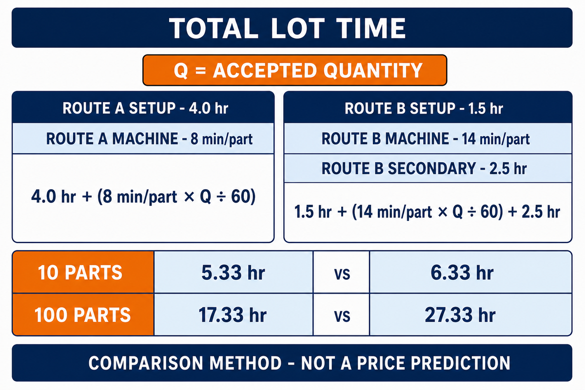
Worked example: suppose Route A needs 4.0 hr of setup and 8 min/part of machine time, while Route B needs 1.5 hr of setup, 14 min/part of machine time, and 2.5 hr of secondary work. For 10 parts, Route A uses 4.0 + (10 × 8 ÷ 60) = 5.33 hr; Route B uses 1.5 + (10 × 14 ÷ 60) + 2.5 = 6.33 hr. For 100 parts, the same assumptions become 17.33 hr versus 27.33 hr. Route B has the shorter setup yet the longer modeled lot time. This fictional calculation excludes rates, inspection, scrap, and acceptance risk, so it’s a comparison method, not a price prediction.
| Input | Supplier A | Supplier B | Why it changes accepted-part cost | Limitations / not suitable for |
|---|---|---|---|---|
| Controlled revision | Record | Record | Prevents scope mismatch | Do not compare different drawings |
| Quantity and batch | Enter | Enter | Changes setup weight | No universal crossover |
| Stock assumption | Enter | Enter | Changes removal and handling | Material condition must match |
| Programming | Included/excluded | Included/excluded | One-time cost differs | Reuse assumptions must be stated |
| Setup and tooling | Enter | Enter | Jaws and fixtures can dominate small lots | Separate reusable assets |
| Process sequence | List | List | Exposes secondary work | Machine label alone is insufficient |
| Inspection scope | List | List | Reports and sampling add work | Acceptance method must match |
| Post-processing | List | List | Adds logistics and dimensional risk | Sequence must be explicit |
| Exclusions and reject rule | Record | Record | Changes risk allocation | Do not infer from unit price |
Procurement takeaway: lower machine time can lose to extra setup, secondary machining, inspection, or rework. Compare the same accepted quantity and document scope before deciding that a turning process or CNC milling process is cheaper.
7. When a Part Needs Both Milling and Turning
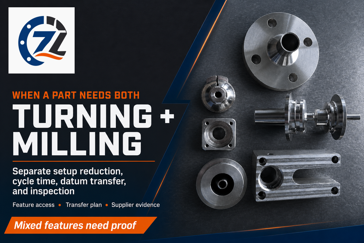
A part needs both milling and turning when rotational and prismatic features carry important functional relationships. The work may run on a mill-turn center, a CNC turning center with live tooling, or separate machines. Choose among them by datum transfer, tool access, spindle capability, quantity, inspection state, and supplier evidence.
Industrial machinery suppliers may propose 5-axis milling machines, CNC milling and turning services, or a sequence that combines CNC turning and CNC milling on a lathe and a milling machine. Precision and efficiency must still be demonstrated against the same feature, datum, quantity, and inspection requirements.
A 2026 peer-reviewed turn-milling experiment likewise keeps mixed-process results tied to the named workpiece, tool geometry, cutting conditions, and surface objective rather than to a machine label.
“The most efficient shops are those with machining centers that bring multiple processes or multiple steps together and make them work as one.”
Thiessen’s statement describes an integration direction, not a guarantee that every combined machine will lower cost. Buyers still need the process sequence, spindle and live-tool assumptions, transfer plan, and inspection handoff for the actual part.
A supplier-side applications-development director quoted in American Machinist reported a B-axis multitasking architecture that reduced setup time while cycle time increased with a single tool spindle. That case-bound counterexample is why the Setup Transfer Risk Budget keeps setup count and cycle duration separate. Software, simulation, second-spindle transfer, simultaneous-cut capability, and available tools can decide whether a mill-turn label creates value.
When a Combined Route Breaks Down
Combined routes are poor defaults when their main advantage exists only on paper. Warning signs include inaccessible critical features, a transfer that can’t preserve the datum, a long tool that loses rigidity, trapped chips, or inspection that requires re-locating the part anyway. One machine can also carry a high programming and setup burden for a small lot, while separate operations may use simpler proven workholding.
The opposite failure matters too. Separate machines can add re-chucking, accumulated uncertainty, queue time, and duplicated inspection. The decision isn’t “advanced CNC” versus old equipment. It’s whether the proposed architecture controls the important relationships with acceptable evidence. Ask the supplier to identify the exact feature where the combined route removes a transfer and the exact feature where it doesn’t.
Do
- Ask which critical datum stays loaded
- Separate setup time from cycle time
- Request the tool and transfer assumptions
- Match inspection to the combined sequence
Don’t
- Assume live tooling reaches every feature
- Treat one setup as zero transfer risk
- Compare machine labels without the sequence
- Convert one case result into a category claim
What Are the Downsides of CNC Turning?
CNC turning is constrained when the part lacks a useful rotational axis, when flats and multi-face features dominate, or when off-axis access needs extensive live tooling or secondary milling. Chucking can distort thin walls, interrupted surfaces can challenge stable cutting, and re-gripping can add runout or datum-transfer risk. Turning remains highly effective for cylindrical parts; the downside is prescribing it from stock shape while ignoring the functional feature stack.
8. Send a Quote-Ready Process Brief
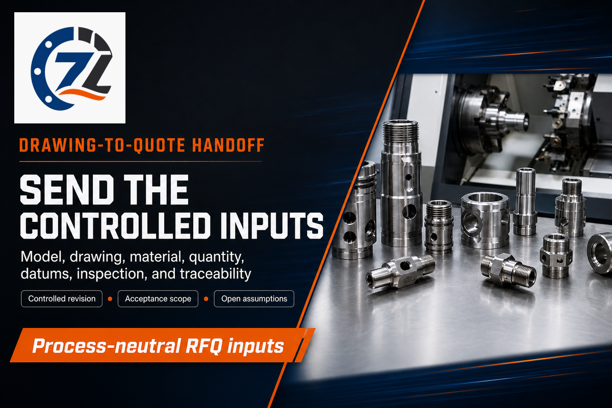
A quote-ready process brief gives every supplier the same model, drawing revision, material condition, quantity, critical features, datums, post-processing, inspection, traceability, and document scope. It should describe required outcomes without prescribing a machine unless the manufacturing route is a controlled design requirement.
If an RFQ asks what’s the difference between the routes, require each supplier to describe its milling work and every other process in manufacturing the accepted part. That common scope can increase efficiency in comparison without claiming that one route is always faster.
A practitioner article hosted by NIST’s Manufacturing Extension Partnership warns that a unit-cost focus can miss quality documentation, lot control, supplier scale, and dependence on particular equipment or personnel. The page carries an author-view disclaimer and is treated here as sourcing guidance, not an institutional NIST position or measurement standard. Add those fields when continuity or traceability affects acceptance.
Process brief to copy into an RFQ
- Controlled three-dimensional model and two-dimensional drawing revision
- Material specification, supplied condition, and approved substitutions
- Prototype, pilot, and repeat-batch quantities with release pattern
- Critical features, datum scheme, and functional relationships
- Threads, surface requirements, deburring, heat treatment, coating, and cleaning
- Inspection method, sampling, measured report, and gauge requirements
- Lot traceability, material records, and quality-document scope
- Capacity continuity and critical machine or personnel dependencies
- Permission for the supplier to propose milling, turning, or a mixed route with assumptions
For process-specific commercial review, use Zhenling’s CNC milling service and CNC turning service pages. Use the milling, turning, and multi-axis route comparator when three process families need comparison; use the turning-versus-milling route screener when rotational-feature suitability is the narrower question. This article only prepares the drawing inputs for those tools.
Key takeaway
A defensible process brief identifies the controlling datum, transfer risks, and acceptance evidence before a supplier or interactive tool recommends a manufacturing sequence.
Need a drawing-led RFQ brief?
Send the model, controlled drawing, material condition, quantity, critical datums, and inspection scope for review. Use Zhenling’s published route screener to organize those inputs, distinguish the relevant tool path, and document acceptance questions before requesting a quotation or supplier process proposal.
Frequently Asked Questions
What is the main difference between CNC milling and turning?
In CNC milling, the cutter rotates around a fixtured part; in CNC turning, the workpiece rotates against a tool to create rotational features efficiently and consistently.
CNC milling normally rotates a multi-edge cutting tool while the workpiece remains fixed or indexed in a fixture. CNC turning normally rotates the workpiece in a chuck while a tool cuts its outside or inside diameter. Motion makes turning natural for rotational features and milling natural for flats, pockets, slots, multi-face holes, and irregular geometry.
Which is more accurate, CNC milling or CNC turning?
Neither process is universally more accurate because feature geometry, machine state, workholding, thermal condition, material response, datum transfer, and measurement method all affect finished-part evidence.
Finished-part accuracy depends on the critical feature, machine condition, workholding, tool, thermal state, material, setup count, and measurement method. Turning can control diameters and coaxial relationships efficiently, while precision milling can control prismatic and multi-face features. Drawing requirements and the inspection plan should define acceptance evidence instead of relying on a process label.
Is CNC turning cheaper than CNC milling?
CNC turning can cost less for suitable round parts, but accepted-part cost still depends on setup, secondary work, inspection, reject exposure, quantity, and quotation scope.
Fair comparisons include stock, programming, setup, fixtures or jaws, cycle time, secondary operations, inspection, reject exposure, and quantity. Bar-fed cylindrical components may suit turning well, while a secondary milling transfer can remove that advantage. Compare accepted-part cost from matched quotation scopes rather than public hourly rates or a fixed percentage claim.
Can milling and turning be combined on one part?
Milling and turning can be combined on a mill-turn center, through live tooling, or as separate operations with a controlled datum-transfer and final inspection plan.
Mill-turn centers, live tooling, or separate machines can combine the operations. Route choice depends on features, datums, quantity, and inspection.
What should I send for a milling-versus-turning review?
Useful reviews start with the controlled model, drawing revision, material condition, order quantity, batch pattern, critical datums, post-processing, inspection method, and required final acceptance evidence.
Send the three-dimensional model and controlled drawing, then identify the material specification and supplied condition, order quantity and batch pattern, critical dimensions, datum scheme, thread and surface requirements, and any heat treatment, coating, or cleaning step. Mark the features that control function, the dimensions that need measured reports, and whether the supplier may propose a mixed route. Add packaging, lot traceability, quality records, and document requirements when they affect acceptance. If two suppliers are quoting, ask both to state the assumed process sequence, setup count, inspection method, and exclusions. These inputs make quotations comparable without forcing the buyer to prescribe an unsafe machining route.
How This Route Guide Was Built
Route-guide research separates process definitions from finished-part capability, then connects CNC milling and CNC turning to drawing features, datums, inspection, and quotation scope. Public standards, government research, academic studies, and attributed practitioner guidance support the analysis; no private Zhenling production result or unverified technical-team review is claimed.
Attribution note: the supplier-selection item below is a practitioner article hosted by NIST MEP and carries an author-view disclaimer. The American Machinist counterexample comes from a supplier-side applications-development practitioner, not an independent controlled trial.
References & Sources
- Effects of machining mechanism and cutting parameters in turn-milling — The International Journal of Advanced Manufacturing Technology
- Workpiece setup optimization for five-axis machining — Advances in Mechanical Engineering
- Automated tool-change movement analysis — Boeing and National Institute of Standards and Technology
- Machine tool calibration, measurement, modeling, and compensation — National Institute of Standards and Technology
- Comparative analysis of production test parts — National Institute of Standards and Technology
- ISO 230-2:2014 machine tool test code — International Organization for Standardization
- ISO 10791-2:2023 machining centre geometric tests — International Organization for Standardization
- In-process measurement and compensation of machine tool thermal deformations — National Institute of Standards and Technology
- Machine-specific institutional rates — Texas State University
- Manufacturing cost and time estimation research — Journal of Intelligent Manufacturing
- IMTS 2026 manufacturing technology perspective — Association For Manufacturing Technology
- Multitasking technology for mill-turn lathes — American Machinist
- Eight ways to improve supplier selection — NIST Manufacturing Extension Partnership
Related CNC Machining Resources
- CNC machining service hub guide for the wider supplier and process context
- CNC milling process guide for milling-specific planning
- CNC turning design and inspection guide for rotational features
- milling, turning, and multi-axis route comparator for an interactive check
- Zhenling process line router for a broader manufacturing handoff