Get in touch with Zhenling Company

Updated August 2026
Magnesium CNC machining is feasible, but “magnesium” is not a process recipe. Any transferable plan must identify the alloy and temper, stock condition, operation, tool and edge state, chip form, workholding, machining medium, surface state, and inspection method. Change one field and a published result may no longer answer the real part question.
Direct answer: Machine the named magnesium alloy only inside a documented material, cutting, chip-state, workplace-safety, and inspection envelope. Published parameters become project evidence only when their alloy, tool, operation, medium, test method, and applicability limits still match.
Key points
- Solid stock, coarse chips, fines, and dust are different evidence states.
- Low cutting force does not prove low process risk or stable released geometry.
- Study temperatures and wear values stay attached to their test methods.
- Missing transfer fields become a validation question, not a generic setting.
This guide explains the mechanisms behind those fields. It introduces two practical tools: The 9-State Magnesium Risk Envelope separates solid stock, chips, fines, and dust before a safety statement is applied, while The 6-Field Alloy-to-Acceptance Evidence Strip tests whether a study can inform a drawing or inspection decision. Broader application context appears in the CNC machining industry applications hub. This article does not claim a Zhenling capability, fixed parameter, tolerance, finish, price, or lead time.
Magnesium Is a Material Family, Not a Machining Setting
A magnesium label identifies a material family, not a complete cutting condition. Alloy designation, temper, product form, stock route, supplied condition, governing specification, and material certificate remain separate identity fields. Until those fields are known, a speed, feed, tool-life result, or surface observation cannot be transferred responsibly.
| Identity field | What it can establish | What it cannot establish |
|---|---|---|
| Alloy designation | Named chemistry family, such as AZ31B or AZ91D | Temper, stock history, tool, or cutting setting |
| Temper and supplied condition | Declared material state at receipt | Behavior after a different thermal or machining history |
| Product form and route | Cast, wrought, sheet, plate, bar, or other controlled form | Equivalence across unlike stock routes |
| Specification and record | The document, revision, and lot evidence to check | A universal CNC machining recipe |
The distinction is visible even in the ASTM nonferrous standards directory. ASTM lists separate documents by magnesium product form and purpose, including B951-11(2025) and B296-20. Those identifiers help a material owner locate the controlled scope; the public directory does not turn either document into a cutting chart. Use the broader CNC material-selection framework to organize the application question, while the applicable specification and supplied record must still be read together.
AZ31B and AZ91D also should not be merged because both begin with “AZ.” A dry-turning observation for AZ31B, a rough-milling observation for AZ91D, and a surface-treatment result for another material state answer different questions. Alloy identity narrows the search. Completeness across the evidence-envelope fields determines whether the result belongs to the project.
Nor should pure magnesium, wrought stock, and a die-cast alloy be treated as one supplied condition. Search copy may call magnesium the lightest structural metal, but “lightest,” “structural metal,” and “lightweight material” are application language, not certificate fields. Characteristics of magnesium must remain alloy-specific. Comparing magnesium and aluminum has the same limit: results for aluminum alloys do not become magnesium process evidence.
Why Magnesium Can Cut Easily Without Being a Casual Process
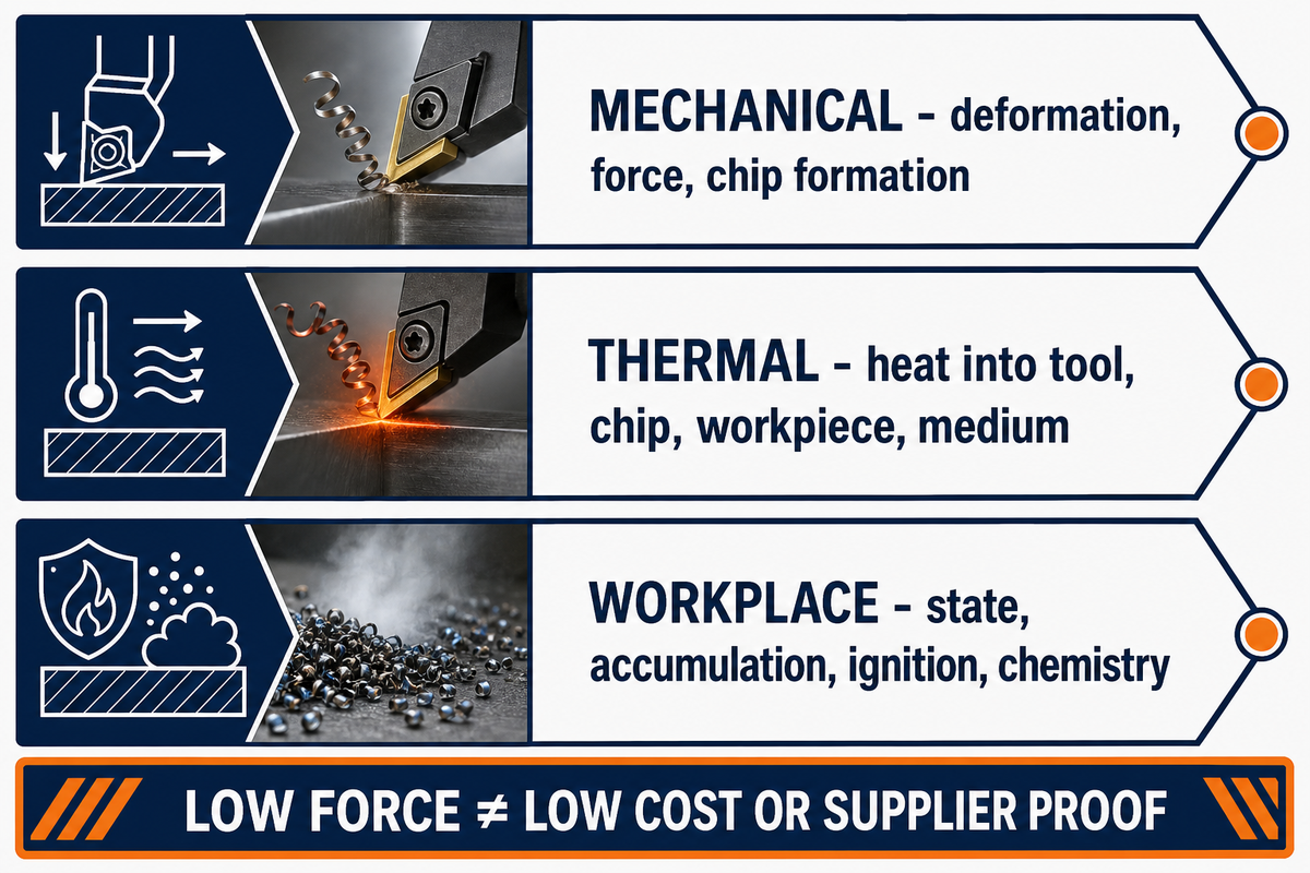
“Easy to machine” usually describes part of the mechanical cutting response. It doesn’t prove that heat, chip accumulation, tool condition, surface change, workholding, or workplace risk is controlled. Machinability and process safety overlap at the cut, but neither one can substitute for the other.
Machinability can help you ask
- How does the named alloy form a chip?
- Where does cutting heat leave the contact?
- What surface and edge signals change first?
- Which observation should be held constant?
Machinability cannot prove
- That every magnesium alloy uses one parameter table
- That chips, fines, and solid stock share one risk state
- That a low force guarantees a stable thin wall
- That one study releases a production process
Mechanical response concerns deformation, force, chip formation, and the way a sharp edge shears the workpiece. Thermal response concerns heat generation and the paths into the tool, chip, workpiece, and surrounding process. Chemical and workplace response concerns the material state, accumulation, ignition opportunities, machining-medium chemistry, and the site controls that govern the operation. A useful review keeps all three tracks visible.
Magnesium is also discussed for high strength relative to mass, strength-to-weight ratio, vibration damping, automotive and aerospace structures, and housings for electronic devices. Those are possible design contexts, not proof that one alloy fits an application. Lower cutting force may reduce one mechanical load without validating surface integrity, fire safety, or the complete machining time.
This separation also prevents a commercial shortcut. Low cutting force doesn’t establish low project cost, short lead time, or supplier suitability. Those answers require a drawing, quantity, material route, inspection plan, and current supplier evidence. In an informational guide, the defensible claim is narrower: magnesium can be machined, but every meaningful result remains conditional.
From Shear Zone to Chip: Where Heat and Energy Go
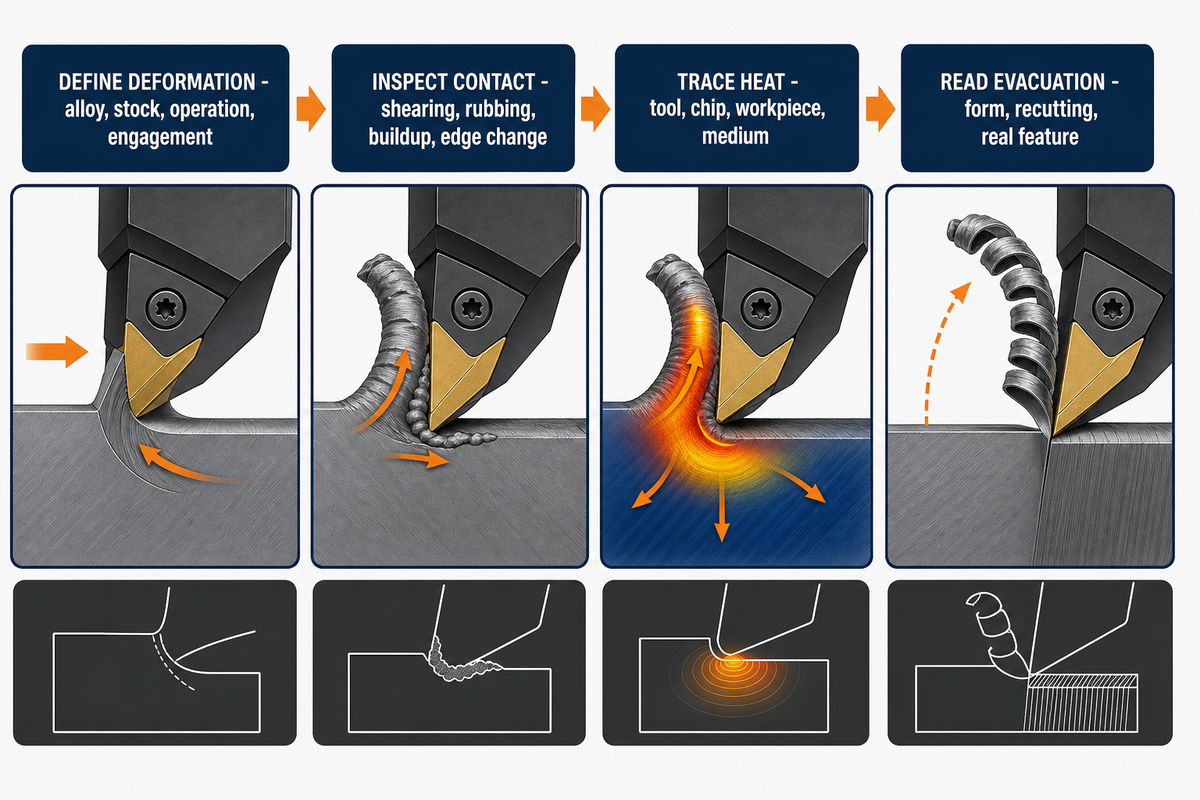
Cutting energy moves through a chain: the work material deforms, the chip slides over the tool, the flank may rub the new surface, and the chip must leave the engagement. Edge geometry, wear, engagement, chip thickness, evacuation, and machining medium can change several links at once.
- Define deformation: record the alloy, stock condition, operation, and actual engagement that create the chip.
- Inspect the contact: distinguish productive shearing from rubbing, buildup, or a changing edge.
- Trace the heat paths: consider the tool, chip, workpiece, and medium instead of blaming one programmed value.
- Read evacuation: connect chip form and recutting to the real pocket, bore, wall, or open cut.
One 2025 AZ91D dry rough-milling study shows why the envelope matters. Its tests used carbide end mills with 20° and 50° helix angles, cutting speeds of 400–1,200 m/min, feed per tooth of 0.05–0.30 mm/tooth, 6 mm axial depth, and 14 mm radial engagement. These are study conditions, not recommended settings.
That paper reported 507.1 °C average and 515.1 °C maximum for chips produced at 0.15 mm/tooth and 6 mm axial depth in an off-machine heating-plate ignition test. Those values were not cutting-zone temperatures. Removing the test method would reverse the evidence meaning and turn a bounded ignition experiment into a false machining threshold.
When a surface mark, changing chip, or temperature concern appears, don’t change speed, feed, tool, and medium together. Record the edge and chip state, then choose one separating observation. Diagnostic work should keep the next check interpretable instead of guessing a root cause from appearance.
For CNC machining magnesium, wording matters. Machining of magnesium describes the full controlled system, while milling of magnesium names only one operation. Every CNC-machined result still needs its material and measurement state; the program name alone can’t supply either one.
The 9-State Magnesium Risk Envelope
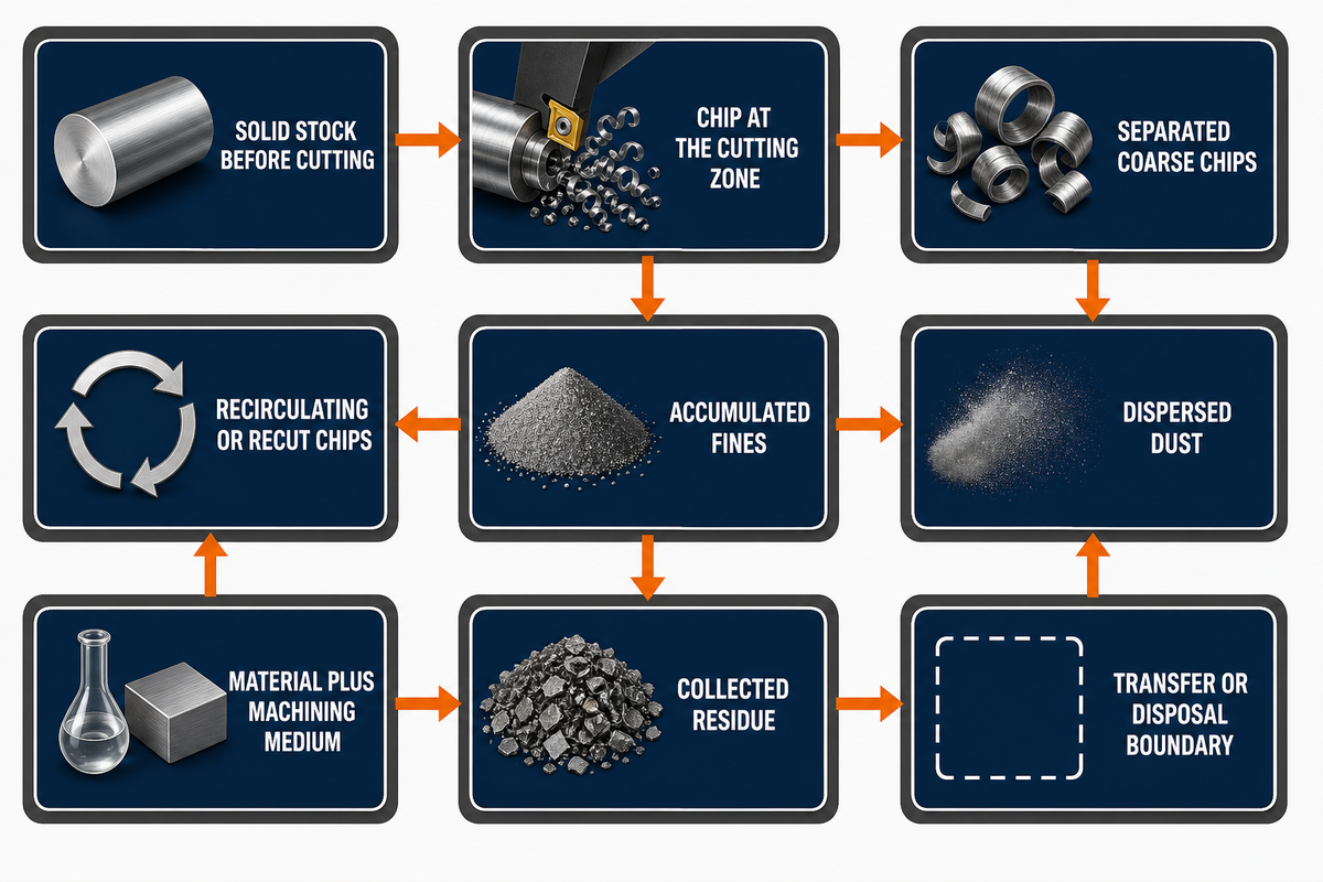
The 9-State Magnesium Risk Envelope classifies the material state before a safety statement is applied. Solid stock, coarse chips, accumulated fines, airborne dust, and contaminated residues can present different questions. This map records the energy path, accumulation, incompatible conditions, owner, and governing workplace document without prescribing a universal procedure.
“Any combustible material can burn rapidly when in a finely divided form.” U.S. Occupational Safety and Health Administration, Combustible Dust: An Explosion Hazard
| Material or transition | Energy path to define | Accumulation or incompatibility question | Decision owner and evidence |
|---|---|---|---|
| Solid stock before cutting | Handling, impact, and incoming condition | What controlled operation creates the next state? | Material and process owners; identity record |
| Chip at the cutting zone | Shearing, friction, local heating | How does the chip leave the engagement? | Process owner; operation and chip-path review |
| Separated coarse chips | Residual heat and nearby energy sources | Where do chips travel, cool, and collect? | Production and safety owners; collection-state assessment |
| Recirculating or recut chips | Repeated tool contact and surface contact | Can the real feature trap or redirect chips? | Process owner; evacuation observation |
| Accumulated fines | Ignition sources and local disturbance | Where can finely divided material build up? | Site safety owner; current hazard assessment |
| Dispersed dust | Ignition, dispersion, and confinement | Can material become airborne in a confined area? | Site safety owner; applicable workplace document |
| Material plus machining medium | Thermal contact and chemical interaction | What is the exact medium, condition, and compatibility basis? | Process and safety owners; current product and site evidence |
| Collected residue | Handling, transfer, and nearby energy sources | How are states identified and segregated? | Site owner; approved housekeeping and storage procedure |
| Transfer or disposal boundary | Movement between people, areas, or containers | Does ownership or material condition change? | Site owner; approved transfer, disposal, and emergency procedure |
Machining-medium chemistry deserves its own row. One 2003 JSME abstract examined hydrogen generation while machining magnesium alloy in several machining media, making medium chemistry an independent variable. It doesn’t support a universal “wet” or “dry” rule. Likewise, OSHA’s public guidance gives condition-specific examples for finely divided metals, and its fire-protection appendix contains both general limitations and engineered magnesium-facility context. Extracting one sentence as a shop procedure would discard the scope.
NFPA’s public development pages show that NFPA 484 was consolidated into the 2025 edition of NFPA 660. That’s a document-identity update, not proof that a facility complies with its requirements. Qualified site owners must resolve the current applicable standard, local requirements, hazard assessment, training, housekeeping, storage, disposal, and emergency plan. This article intentionally provides no coolant, extinguishing, cleanup, or emergency instruction.
Safety-language boundary: Search results may contain phrases such as “flammable,” “spark,” “magnesium fire,” “Class D fire,” “Class D fire extinguisher,” “Type D fire,” “water-based,” “chips are wet,” “system for chip removal,” “avoid tight clearance angles,” and “safe production.” None of those phrases is a procedure in this guide.
Working with magnesium requires each machine shop to distinguish magnesium chips and dust from solid stock. It must not assume one state is difficult to ignite because another test looked stable. Fire safety, extinguisher selection, medium compatibility, housekeeping, and emergency response belong to the current site assessment and qualified owner.
Tool Geometry and Edge Condition Change the Heat Path
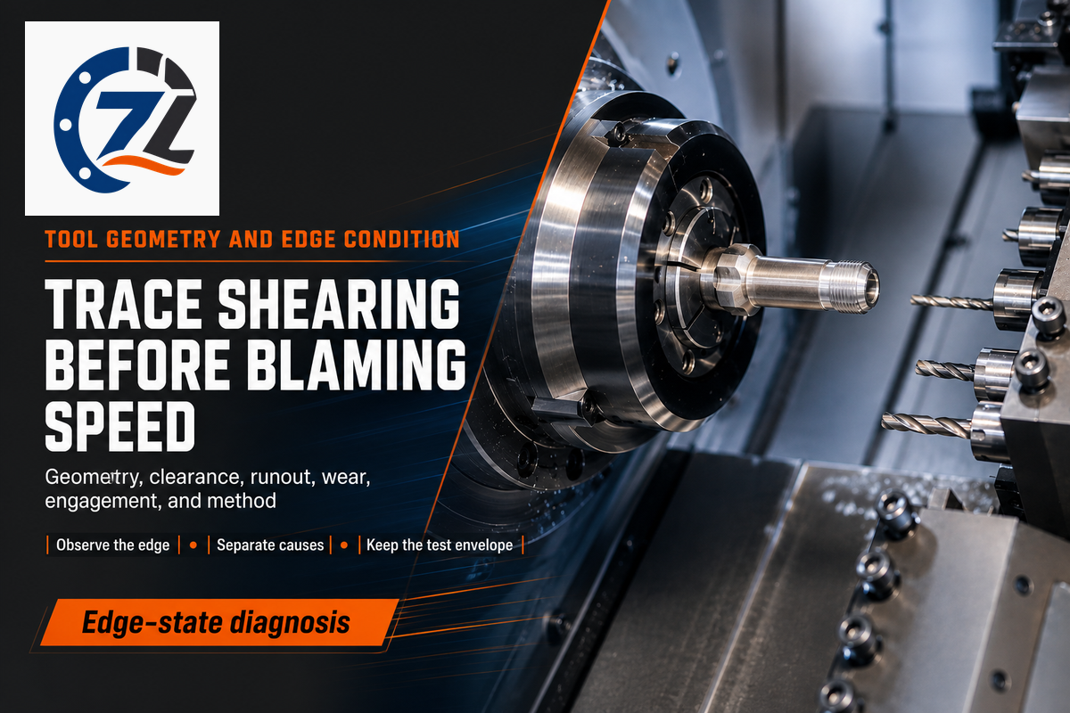
A sharp edge, positive geometry, clearance, tool material, coating, runout, and wear state influence how magnesium shears and how much contact becomes rubbing. None is an isolated cure. Useful diagnostic work pairs each visible signal with competing causes and a separating observation.
| Signal | Competing causes | Separating observation |
|---|---|---|
| Changing flank wear | Edge loading, rubbing, runout, engagement, material state | Trend wear location at a defined cut interval |
| Surface streak or smear | Buildup, recutting, edge damage, support | Compare edge and chip condition before changing the path |
| Chip form shift | Speed, feed, edge wear, operation, medium access | Hold the tool state and inspect the real evacuation route |
| Burr or exit damage | Edge state, exit support, tool path, local geometry | Compare the same exit feature with support held constant |
One AZ31B dry-turning study used a coated carbide insert at 65–115 m/min, 0.1–0.2 mm/rev, and 0.5–1.0 mm depth of cut. Reported flank wear ranged from 89.56 to 299.34 µm across its test conditions. Because the reviewed public record didn’t state the supplied material condition, even a precise micrometre value remains incomplete evidence.
Rather than identifying the smallest wear value reported in the test paper, retain its full evidence envelope. That includes alloy, supplied condition, tool, operation, engagement, interval, wear measure, and measurement method. If any one field is different, treat the published paper as a question generator rather than a published set-up sheet.
“Avoid tight clearance angles” appears in public machining advice, but the phrase doesn’t define a tool. Clearance, rake, edge preparation, material, coating, runout, engagement, and wear state must be recorded together before a geometry claim transfers.
Milling, Turning and Hole-Making Expose Different Failure Signals

Milling interrupts contact, turning can create a more continuous chip, and hole-making encloses the edge and evacuation path. Those mechanics change the useful observations. A result from one operation shouldn’t cross into another unless the tool, engagement, support, chip path, and measured endpoint remain comparable.
| Operation or state | Mechanism to preserve | Useful signal | Transfer stop |
|---|---|---|---|
| Face milling | Interrupted entry, exit, and changing tooth contact | Edge-by-edge wear and surface pattern | Path, insert, or engagement changes |
| Peripheral milling | Radial and axial engagement along the tool path | Load at entries, exits, and corners | Wall support or engagement changes |
| Slot or pocket milling | Enclosed chip path and recutting opportunity | Evacuation, chip return, and wall marks | Depth, access, or cavity shape changes |
| Turning | Continuous contact, chip breakage, diameter, and support | Wear location, chip form, and finish trend | Insert, diameter, or material condition changes |
| Drill entry | Initial centering, support, and edge contact | Entry mark, force trend, and runout evidence | Entry geometry or support changes |
| Enclosed drilling | Thrust, flute evacuation, and depth-dependent access | Chip packing, temperature method, and diameter | Depth, drill geometry, or access changes |
| Drill exit | Remaining support and breakout geometry | Exit edge, burr, and local finish | Wall thickness or exit support changes |
| Helical hole milling | Orbital path and interrupted evacuation | Force, temperature method, chip size, diameter, and finish | Tool, orbit, feature, or study envelope changes |
| Post-cut release | Removal of fixture restraint after the operation | Feature and datum in supported and released states | Workholding or measurement state changes |
A 2021 AZ31 dry-machining comparison used an 11.5 mm two-flute drill for conventional drilling and an 8 mm solid-carbide end mill for helical hole milling. Its abstract reports directional differences in force, temperature, diameter accuracy, surface finish, and chip evacuation. It doesn’t give a universal superiority rule because the tools and mechanics were different and the public abstract doesn’t supply every output value. A separate milling, turning, and drawing-inspection comparison explains the broader route distinction without converting this AZ31 study into a shop setting.
How can magnesium be machined safely?
Start by defining the exact alloy and supplied condition, then map every transition from solid stock to chips, fines, dust, and collected residue. Record the operation, tool and edge, machining medium, enclosure, evacuation route, accumulation points, and potential energy sources. A current site risk assessment must decide the controls, housekeeping, storage, disposal, training, and emergency response under the applicable requirements.
Published machining studies can explain mechanisms only inside their test envelopes. They cannot approve a facility procedure. Before changing a setting, confirm that the material state and decision owner are known and that the workplace procedure covers the actual operation.
Thin Walls Can Move After the Tool Leaves
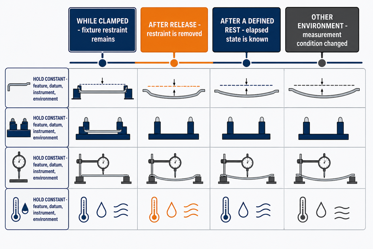
A magnesium feature may read differently while clamped, immediately after release, after a defined rest, or under another measurement environment. Those operation, tool, and chip-state observations carry into the measurement sequence. Cutting load, local heat, fixture restraint, removal balance, and released residual stress are competing contributors. Machine accuracy alone can’t explain the sequence.
In one 2023 AZ31B milling and post-treatment study, 14 test pieces showed measured surface residual-stress changes of 19.31–50.52 MPa after the selected stress-relief annealing conditions, reported as 56.14–67.29% reductions. Those values show that machining and post-treatment state can affect the measured surface. They don’t predict wall movement, authorize an annealing cycle, or establish a tolerance.
- Clamped cut: record the removal pattern, support, tool, and feature state during machining.
- Released part: repeat the declared feature and datum after fixture restraint is removed.
- Defined rest or environment: record elapsed time and measurement conditions without inventing a universal wait period.
- Acceptance state: connect the result to the drawing, method, sampling rule, and approved criterion.
Keep the feature, datum, instrument, and environment constant during a useful diagnostic comparison of declared states. If the tool changed at the same time as the clamping strategy, the result can’t assign cause to either one. If the paper studied residual stress but the project question is dimensional movement, the missing causal bridge must remain visible. Drawing-led discipline also appears in a CNC manufacturability guide, where geometry and inspection assumptions are resolved before release.
Freshly Cut Surfaces Change the Post-Machining Question
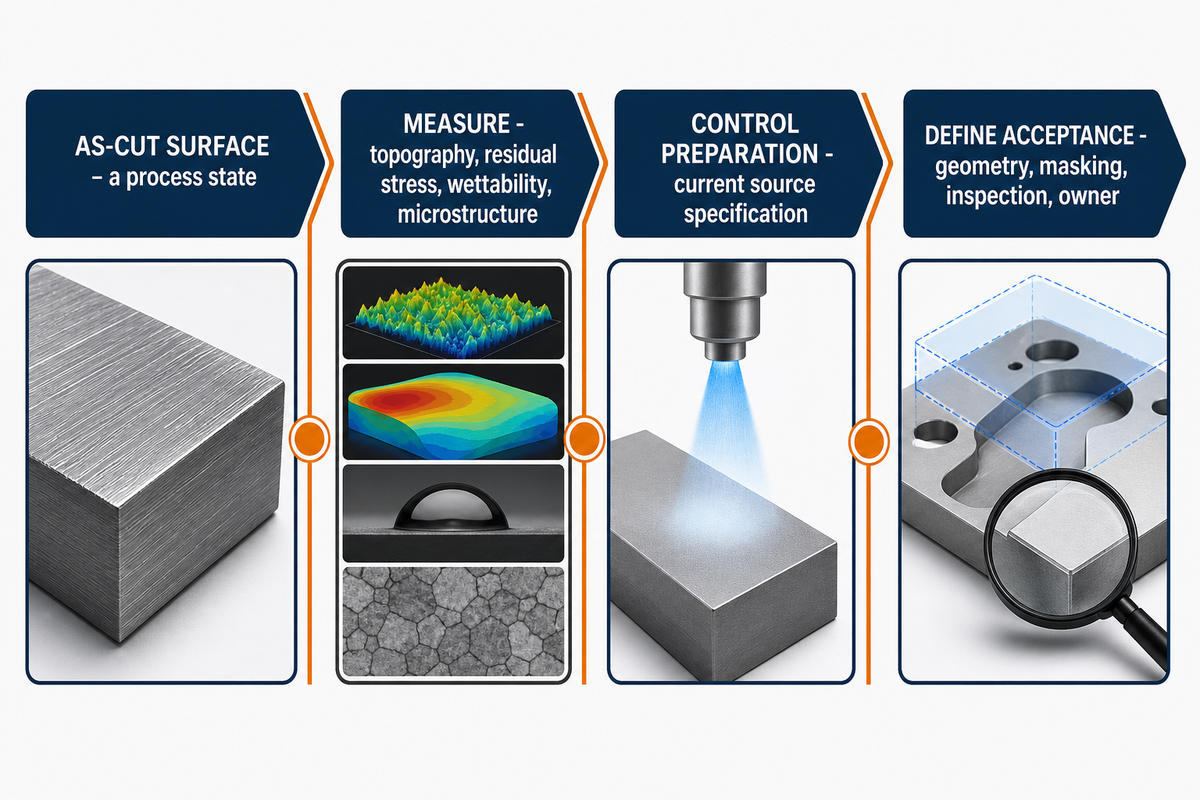
A freshly machined magnesium surface is a process state, not simply a color or roughness target. Alloy, machining medium, topography, residual stress, transformed layers, contamination, elapsed time, geometry, service environment, and finishing specification can all belong to the downstream evidence.
An ORNL record for a CIRP study on AZ31 describes measurements of surface topography, residual stress, wettability, microstructure, and transformed-layer depth after machining. Its corrosion work used an in vitro human-like environment and included a cryogenic low-feed condition. That scope is valuable because it identifies measurable surface variables; it is not a general recommendation for industrial corrosion resistance or a finish selection rule.
ASTM publicly lists D1732-03(2023) as practices for preparing magnesium-alloy surfaces for painting. The catalog establishes the document identity and revision, not every controlled instruction or proof that painting is correct for a part. A downstream plan still needs the exact alloy, service condition, current finish specification, cleaning and handling state, geometry, masking, inspection, and accountable process owner.
This is where “apply a coating later” fails. It omits the material state before treatment, the controlled preparation route, the functional requirement, and the acceptance test. A guide can name those interfaces. Available finishes and performance commitments remain drawing-specific commercial questions.
Powder coating and other surface finishes may appear in a project specification, but neither is a universal sequel to machining. The source-controlled preparation, chemistry, geometry, masking, service environment, and acceptance test must remain attached to the chosen route.
The 6-Field Alloy-to-Acceptance Evidence Strip
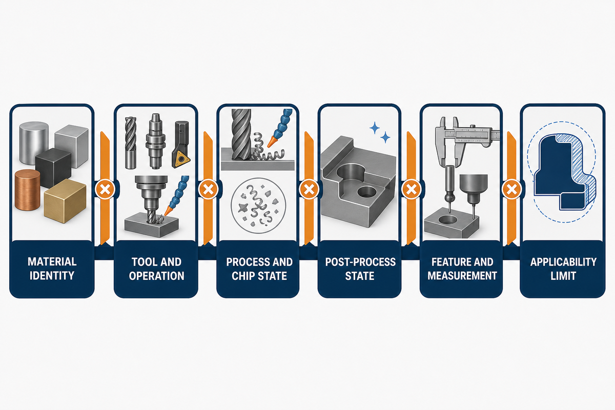
The 6-Field Alloy-to-Acceptance Evidence Strip asks whether six fields remain intact from a source to a project. A value with units isn’t strong evidence when its alloy, tool, process, post-process state, measurand, or applicability limit is missing. Any blank field stops automatic transfer.
| Field | Record from the source | Project comparison | Stop-transfer condition |
|---|---|---|---|
| 1. Material identity | Alloy, temper, product form, stock condition | Certificate and approved substitution | Generic “magnesium” or unlike route |
| 2. Tool and operation | Tool material, geometry, condition, milling, turning, or hole-making | Actual tool, feature, path, and access | Operation or edge state differs |
| 3. Process and chip state | Speed, feed basis, engagement, medium, chip form | Bounded setup and evacuation route | Units exist but the basis or state is absent |
| 4. Post-process state | As-cut, treated, prepared, coated, or other declared state | Actual sequence and controlled specification | A treatment result is applied to an as-cut part |
| 5. Feature and measurement | Feature, datum, method, environment, elapsed time | Drawing measurand and inspection plan | Different endpoint or undefined measurement state |
| 6. Applicability limit | Study exclusions, uncertainty, and unresolved variables | What the project still must validate | Source limitation is omitted |
Apply the strip to the AZ91D example. The values 507.1 °C and 515.1 °C retain meaning only when paired with the off-machine heating-plate method, chips from the named milling condition, and the paper’s test envelope. They can’t become cutting-zone limits. Apply it to the AZ31B result: 19.31–50.52 MPa and 56.14–67.29% stay attached to 14 test pieces, the chosen milling and treatment states, and a surface residual-stress endpoint. They can’t become a thin-wall allowance.
A compact transfer check preserves separate values: the AZ91D source began its tested cutting-speed range at 400 m/min and compared 20° and 50° helix tools with 14 mm radial engagement; the AZ31B source bounded reported wear between 89.56 µm and 299.34 µm. These figures improve traceability, not parameter authority.
20°studied helix angle
50°studied helix angle
507.1 °Coff-machine plate-test average
515.1 °Coff-machine plate-test maximum
The strip is useful to quality, production, procurement, and ownership roles because it exposes different gaps. Quality sees an undefined measurand. Production sees an unlike tool or chip path. Procurement sees an incomplete material record. The owner sees where literature ends and a controlled project validation must begin. A blank is not a failure; it is an honest acceptance question.
The same rule separates metal evidence from plastic machining guidance and separates finished magnesium parts from as-cut coupons. If a source studied a different material family, a different post-process state, or an unlike feature, similarity can’t fill the missing evidence field.
Key takeaway
A magnesium machining value transfers only when material, tool, operation, chip and medium state, post-process state, feature, measurement, and source limits remain attached.
Where General Guidance Stops and Project Review Begins
General guidance stops when the answer depends on an actual drawing, alloy and temper, stock route, feature, quantity, inspection deliverable, service condition, or site procedure. Those material and measurement limits become the boundary before any drawing-specific promise is discussed. This guide can organize those unknowns, but it can’t promise a process, tolerance, finish, schedule, price, or production release.
Carry forward the evidence gap instead of a copied parameter: the drawing revision, material record, critical feature and datum, operation, tool and chip state, workholding, post-process state, measurement method, and unresolved applicability limit. The informational query “how to machine magnesium” belongs here, while literal searches such as “Magnesium CNC machining near me,” “Magnesium CNC machining machine,” and “Magnesium CNC machining cost” signal supplier, equipment, or pricing intent. For the commercial handoff, review project-specific magnesium machining requirements. That page owns magnesium service and quotation intent; the general CNC machining service framework covers the broader commercial route. This article remains the educational evidence guide.
Open a Drawing-Specific Project Review
Frequently Asked Questions
The drawing-specific project-review boundary also explains why each answer stays conditional on the material, process, and evidence state.
If magnesium can be dangerous, why machine with it at all?
Magnesium is machined when the defined alloy and application justify a controlled route, with chip state, heat path, workplace risk, and inspection evidence reviewed together.
Designers may value low density, stiffness-to-weight possibilities, damping behavior, or another alloy-specific property. Those benefits belong to the exact material and application; they don’t erase the process question. Solid stock, hot chips, accumulated fines, and dust aren’t interchangeable evidence. Selection therefore needs both a functional material justification and a documented process-risk review. A general “lightweight metal” label can’t establish either one, and an educational article can’t approve the workplace controls.
Why is magnesium hazardous?
The relevant hazard changes with material form, energy path, accumulation, surrounding conditions, and the site controls that govern each transition from solid stock to divided material.
A finished solid part and finely divided process material require different reasoning. Alloy, surface area, chip or dust size, temperature, quantity, dispersion, confinement, ignition opportunities, and interaction with a machining medium can change the question. The useful review asks which state exists, how the operation creates the next state, where material can accumulate, which incompatibilities need assessment, and which current site procedures and applicable requirements govern the work. It shouldn’t replace that assessment with a generic extinguishing or storage tip.
Is it possible to alloy magnesium with other metals for CNC machining?
Yes, commercial magnesium materials are alloy systems, but alloying does not create one shared machining recipe; designation, temper, stock route, operation, and measurement remain separate evidence fields.
Alloying additions help produce different mechanical, casting, forming, corrosion, and service profiles. A machining result still needs the exact designation, temper, product form, stock route, and supplied condition. AZ31B turning data shouldn’t become AZ91D milling guidance merely because both are magnesium alloys. Keep the certificate, source specification, tool, operation, medium, and measurement method attached to any result, then validate the project-specific gaps.
What special storage considerations are there for magnesium parts?
Storage must be based on the exact material form and the facility’s approved procedures, because finished parts, chips, fines, dust, and contaminated residues do not share one handling state.
Finished parts, clean solid stock, hot chips, wet chips, dry chips, fines, dust, and contaminated residues shouldn’t be collapsed into one instruction. Identify the state, quantity, contamination, container or area, nearby energy sources, and transitions created by handling. Qualified site owners must apply the current hazard assessment, applicable requirements, and approved housekeeping, segregation, storage, disposal, and emergency procedures. This guide intentionally gives no universal storage configuration.
Why can machining data from one magnesium alloy fail to transfer to another?
Transfer fails when the material, process, or measurement envelope changes, including alloy, temper, stock route, tool, engagement, medium, post-process state, feature, datum, and acceptance method.
Alloy chemistry, temper, stock route, inclusions, prior processing, and surface condition can change cutting behavior. Transfer also fails when the tool, edge state, operation, engagement, machining medium, chip path, workholding, post-process state, feature, datum, or measurement method differs. A precise number isn’t universal merely because it has units. Use the 6-Field Alloy-to-Acceptance Evidence Strip to expose missing fields, then treat each gap as a validation question. Preserve the source’s endpoint as well: force, temperature, wear, residual stress, roughness, corrosion response, and dimensional movement are different measurands. If the project asks about one while the paper measured another, a similar alloy name can’t bridge the gap. Record the missing bridge and design a controlled check around the actual feature, datum, and acceptance rule.
References & Sources
- ASTM International: Nonferrous Metal Standards Directory
- ASTM D1732-03(2023): Preparation of Magnesium Alloy Surfaces for Painting
- Peer-reviewed AZ91D dry rough-milling and chip-ignition study
- Peer-reviewed AZ31B turning, tool-wear, and chip-morphology study
- Peer-reviewed AZ31B milling and residual-stress study
- AZ31 conventional drilling and helical hole-milling comparison
- Oak Ridge National Laboratory: machining-induced AZ31 surface transformations
- JSME record: hydrogen generation during magnesium-alloy machining in several media
- U.S. Occupational Safety and Health Administration: Combustible Dust
- U.S. Occupational Safety and Health Administration: Hazard Communication Guidance
- U.S. Occupational Safety and Health Administration: Fire Protection Appendix
- NFPA 660: Combustible Dusts and Particulate Solids
Evidence transparency: This public-data guide is an informational companion to the commercial magnesium service page. No private Zhenling magnesium production record, customer outcome, tool-life series, tolerance study, or universal parameter table was supplied. Claims were cross-checked against current public standards directories, official safety pages, and condition-bound research; every study remains limited to its named alloy, tool, operation, and test method. See the Zhenling company background for the organization-level context that’s separate from these public magnesium sources.