Get in touch with Zhenling Company

Made-to-print component machining
Medical CNC Machining
Medical CNC Machining Built Around Your Released Drawing
Our precision CNC machining service begins with an engineering review of the part, material callout, critical features, inspection expectations, and delivery objective. For medical-component RFQs, Zhenling’s standard service scope covers drawing-defined, non-finished components through ordinary CNC routes and the user-confirmed commercial baselines; material grade, drawing, finish, cleanliness, inspection and buyer acceptance remain order-specific and confirmed in the written quotation. Medical CNC Machining enquiries should include non-finished-device component scope, material, drawing, finish, cleanliness requirement and buyer acceptance records. Resolve material, geometry and measurement risks first. Price and timing should follow the documented route, not an equipment category.
Service scope boundary
We machine non-finished components to your approved drawings; we do not design or release medical devices. Device manufacturers retain supplier qualification, regulatory, downstream cleaning, sterilization, assembly, and finished-product release responsibilities.
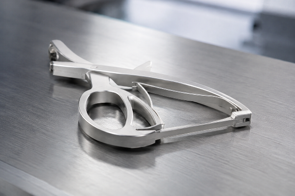
What we review before quoting
- Geometry Features, access, datum logic
- Material Grade and stock route
- Quality Critical dimensions and checks
- Delivery Prototype or production objective
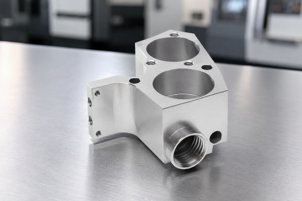
How We Work Before You Send the Drawing
The commitments below let your sourcing team decide whether our machining service fits the project before disclosing detailed files. Feasibility, price, and the final manufacturing process still depend on the released drawing.
-
Within 12 hours
Engineer-reviewed quote response on business days after a sufficient RFQ package arrives.
-
3–5 days
Prototype parts after drawing approval; finishing and shipping are confirmed in the quotation.
-
7–15 days
Production runs after drawing approval, confirmed with your quotation.
-
Minimum quantity per quotation
Single pieces are accepted for feasibility and pricing review.
Processes Selected for the Component, Not the Label
Medical-component RFQs require drawing-specific process and qualification review. Proposed routes may include turning, milling, grinding, boring, wire EDM, drilling or multi-axis machining, but actual equipment, production site and availability must be confirmed for the order. Untoleranced dimensions remain controlled by the released drawing and buyer-specified standard rather than a universal site baseline.
How Our Medical CNC Machining Services Fit a Released Drawing
Within our stated boundary, CNC machining for medical devices means precision machining of non-finished parts to an approved drawing. It does not transfer medical device development, regulatory release, or finished-product responsibility to our manufacturing company.
- Precision machining services: turning, milling, grinding, boring, and wire-cut EDM are matched to the feature set.
- 5-axis CNC machining: considered when complex parts need different access or a more stable datum strategy.
- Machining project inputs: material, tolerance, finish, inspection, quantity, and revision define the reviewed route.
- Machining partner boundary: components for medical equipment remain non-finished until the buyer’s downstream controls are complete.
[PRC-01]
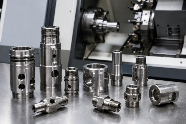
CNC turning
Concentric bodies, threaded features, sleeves, plugs, fittings, and rotational machine parts enter our turning-route review. Milling operations can be added when the drawing combines flats, ports, slots, or cross-holes.
[PRC-02]
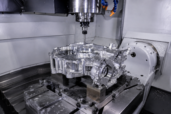
CNC milling
A mill or multi-axis machining center can serve housings, mounts, manifolds, plates, fixtures, and contoured geometry. Feature access and datum strategy decide whether a 3-axis, 4-axis, or 5-axis route reduces repositioning risk.
[PRC-03]
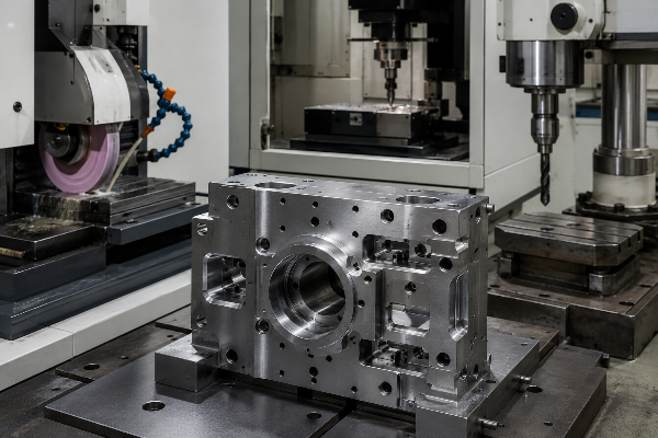
Secondary machining
Grinding, boring, wire-cut EDM, and radial drilling are considered when the drawing calls for the geometry they serve. The route is defined before quoting so a secondary operation is not discovered after the first machine setup.
Prototype and rapid prototyping decisions
- Confirm fit, access, and datum logic before production release
- Separate functional critical features from cosmetic preferences
- Use the same revision reference across model, drawing, and quote
Representative component forms for review
- Housings, mounts, manifolds, fixtures, fittings, sleeves, and plugs
- Made-to-print components specified for diagnostic equipment
- Precision medical component geometry that remains a non-finished part
Stainless Steel Grades We Can Put Into the RFQ Route
For non-finished components for medical devices, our verified scope covers 303, 304, 304L, 316, 316L, and 321 stainless steels. For Zhenling, the precision risk appears when a substitute grade enters the CNC machining process; unlike a material-only quote, our review holds the released grade as the controlling record. Material selection remains the design authority’s decision, while ISO 2768-m applies only to untoleranced metal dimensions and never substitutes for a grade callout.
“The wrong grade can cost you more than machine time because it can invalidate the intended environment. That callout is confirmed before our route is fixed.”
Medical-material review note
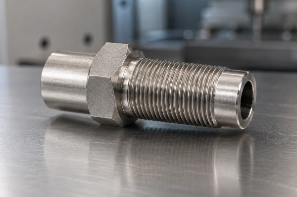
303
Grade 303 enters our review when the released specification prioritizes machinability and the grade is acceptable for the component environment. The drawing remains the controlling record.
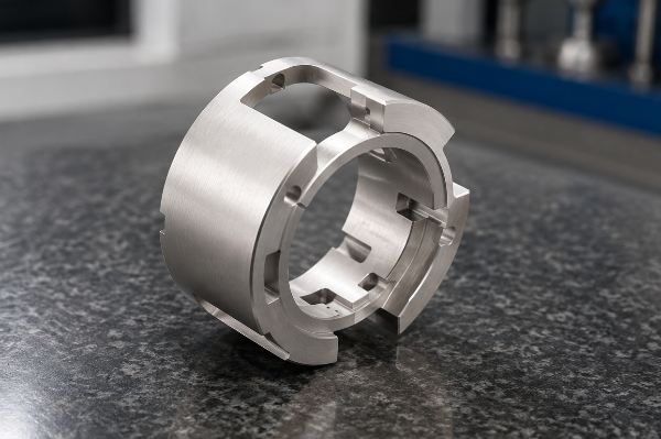
304 and 304L
Part form, stock availability, cutting access, and finish notes are reviewed before the machining process is fixed. The low-carbon grade must be called out explicitly when required.
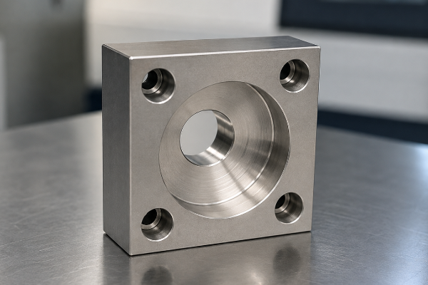
316, 316L, and 321
These alloy grades can be quoted when they appear on the released drawing and the requested geometry fits our machine route. Our route does not substitute one stainless steel grade for another without written drawing control.
As-Machined Finish With Drawing Control
As-machined roughness is controlled by the drawing and written quotation; no universal Ra value is claimed. Poor surface finish becomes a supplier-switch trigger when the acceptance state is not explicit.
Why the location matters
A blanket finish note can add machine time to surfaces that do not affect sealing, motion, cleaning, or assembly. Our review asks which faces carry the function so the CNC machining service can focus control where it changes the result.
What belongs in the RFQ
- Ra value and the surfaces to which it applies
- Directionality or lay requirement, if functional
- Protected edges, no-touch areas, and cosmetic acceptance notes
General Tolerance First,
Critical Features Explicitly Controlled
Untoleranced dimensions, chamfers, datum references and geometric controls are governed by the released drawing and buyer-specified standard. The written quotation confirms which general-tolerance rule, if any, applies to the order.
SYS-CHK // 01
“Our first question is not how tight the machine can hold every dimension. It is which feature controls fit, alignment, sealing, motion, or assembly.”
Engineering Parameters
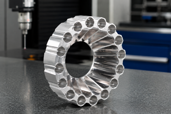
| RFQ or production item | Our published baseline | What controls the final requirement |
|---|---|---|
| Quote response | Within 12 hours on business days | Sufficient drawing and project inputs |
| Prototype timing | 3–5 days after drawing approval | Quoted manufacturing route |
| Production timing | 7–15 days after drawing approval | Quoted manufacturing route |
| Axis classes | Proposed multi-axis route and actual equipment confirmed per order | Geometry, access, and datum strategy |
| Verified stainless grades | 303 / 304 / 304L / 316 / 316L / 321 | Released material callout |
| Untoleranced metal dimensions | ISO 2768-m only when expressly applied | No individual tolerance on drawing; written quotation expressly applies it |
| As-machined surface | Ra 3.2 µm suitable-feature quotation baseline | Drawing-specific finish and acceptance requirements control |
| Order entry | Minimum quantity confirmed per quotation | Drawing feasibility and quoted route |
Unlike a blanket tight-tolerance claim, we confirm against the released feature and its function. Tightest tolerance everywhere is the wrong answer when the trade-off adds inspection and machine time without protecting fit; a standard is not a substitute for supplier qualification.
WARNING
A familiar aerospace drawing convention does not transfer supplier qualification into a medical device program.
“A 0.1 mm mismatch can be functional or irrelevant depending on the design…”
Quote and Lead Time Drivers We Review Up Front
Price is not calculated from part volume alone. Late delivery matters as much as nominal machine capability during prototype work, so access, setups, stock, tolerance, inspection planning, quantity, and revision maturity all enter our route.
Use a readiness score to see which missing inputs are likely to trigger another clarification cycle.
Score the RFQ package →01
Geometry and setups
Deep pockets, thin walls, long reach, cross-holes, and multiple datum orientations can add setup or tool-access risk. Our review looks for a route that protects the critical relationship instead of counting features only.
02
Material and finish
Grade, stock form, removal volume, finish location, and protected surfaces affect both cutting and handling. A clear callout prevents a cosmetic assumption from becoming an avoidable cost driver.
03
Inspection scope
Critical dimensions, sampling expectation, measurement method, and any requested records should be settled before machining. This lets us price the quality plan as part of the manufacturing process.
Critical-to-Quality Transfer Matrix
The drawing is translated into a reviewable chain: the feature, its function, the failure to avoid, the machining control, and the agreed verification. This keeps “precision” from becoming a vague promise and gives the machine shop a practical control point. ISO 2768-m supplies only the general untoleranced-metal baseline; critical features stay under explicit drawing control.
| Drawing input | Risk if unclear | Our review action | Release evidence |
|---|---|---|---|
| Datum structure | Features relate to the wrong origin | Map setup and inspection references | Agreed datum interpretation |
| Thread and edge notes | Missed thread or oversized chamfer | Place each callout in the operation plan | Feature-level check point |
| Surface finish location | Functional face receives the wrong treatment | Separate functional and cosmetic surfaces | Released finish map |
| Critical dimension | General tolerance hides assembly risk | Assign process and verification attention | Agreed inspection method |
| Revision identity | Model, PDF, and purchase order disagree | Confirm one released revision set | Quote and job reference match |
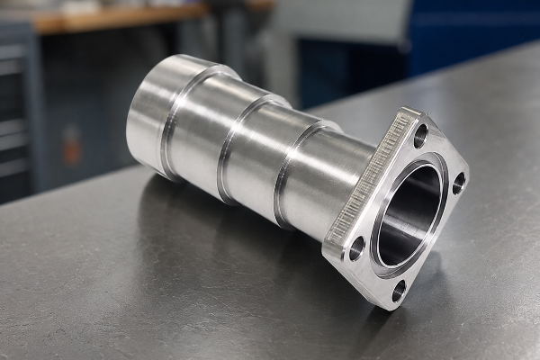
Reliability comes from transfer, not adjectives
For teams producing medical device components, the costliest ambiguity often sits between design intent and the shop-floor instruction. Missing threads on a prototype can make an otherwise acceptable part unusable, so we surface each critical callout before the first cut.
Records are scoped before work begins
The inspection method, sampling expectation, and requested document scope are agreed before stock is committed. Our final check uses the released drawing and the agreed plan.
Build a feature-by-feature matrix for your next sourcing review.
Open the CTQ Transfer Builder →How We Work: Our Six-Step Drawing-to-Production Route
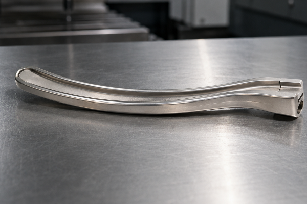
Accepted RFQ inputs include STEP, IGES, PDF and DXF files. If a non-disclosure agreement is executed, it governs the information and transfer route covered by that agreement.
01 //
RFQ intake
Our intake identifies the component revision, quantity, material, finish, delivery objective, and required file set.
02 //
Engineering review
The review checks feature access, datum logic, tolerance, material, inspection expectations, and conflicting notes.
03 //
Route and quote
Routing selects the machine sequence before our engineer-reviewed quotation sets the applicable timing.
04 //
Drawing approval
Approval aligns the released model, drawing, revision, and clarified requirements before scheduling begins.
05 //
Machining and checks
Machining follows the agreed route and controls the features identified in the transfer matrix.
06 //
Final review
Our final review compares the completed part to the released drawing and the inspection scope agreed for the order.
SYS.DATA
| Design choice | Common RFQ effect | Review question |
|---|---|---|
| Tight tolerances on every feature | More control effort without equal functional value | Which relationships drive fit or performance? |
| One cosmetic note for all faces | Extra finishing or handling exposure | Which surfaces are actually visible or functional? |
| Multiple file revisions | Quote and production mismatch risk | Which revision is released for manufacture? |
| Hidden thread or edge expectations | Late clarification or rejected features | Are thread class, depth, chamfer, and break-edge notes explicit? |
How We Work With the Factory Capacity Behind the Review
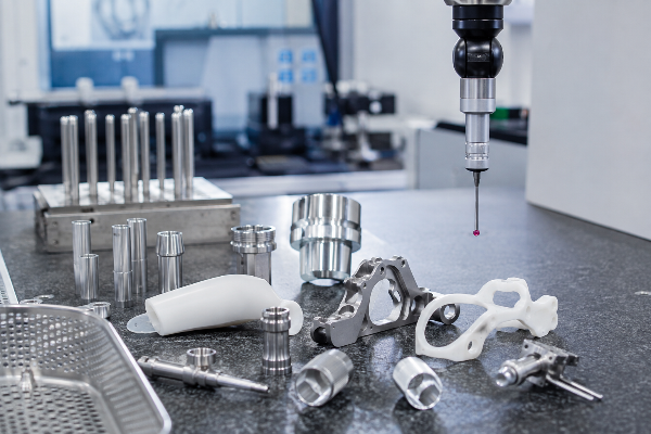
Founded in 2006, our Jiashan factory occupies an 8,000 m² site with a 6,000 m² workshop. Zhenling supports precision custom metal components from drawing review through machining using our stated equipment and stainless steel scope.
-
Turning and milling base
Rotational, prismatic and mixed-feature components may require turning or machining-centre routes; actual equipment, execution site and availability are confirmed per order.
-
Multi-axis access
Our 3-axis, 4-axis, and imported 5-axis machine classes give us options when geometry and datum relationships make repositioning a risk.
-
Supporting processes
Grinding, boring, wire-cut EDM, and radial drilling broaden the routes we can evaluate for a made-to-print component.
-
Qualitative value case
No unsupported savings percentage is attached to our drawing review. The commercial value is simpler: fewer interpretation loops, earlier risk visibility, and a quote built around the intended route.
Quality Assurance Boundaries That Need a Different Qualification Route
A capable CNC machine is only one part of medical manufacturing. Finished medical device manufacturers retain patient-contact qualification, cleanliness, sterilization, regulatory release, and supplier-control responsibilities within their defined quality system and supply chain.
“The wrong choice is treating machine access as a substitute for application qualification. Our review separates the non-finished component scope from the controls that belong to the finished product.”
Medical-scope review note-
01
Finished patient-contact products
Finished implants, surgical instruments or tools with direct patient-contact requirements need a supplier whose documented scope covers the complete requirement. Route that work through the applicable device qualification and release system.
-
02
Materials outside this page
Titanium, PEEK, plastic, and other biocompatible materials require material-specific evidence and an approved route. Use a supplier qualification tied to the exact grade, manufacturing process, cleaning state, and intended application.
-
03
Clean or sterile delivery states
Cleanroom handling, validated cleaning, bioburden control, and sterilization need separately defined controls. Specify the responsible party and acceptance evidence before choosing the machining source.
Medical CNC Machining Tools
medical component rfq checklist
Systematically verify all critical specifications, material compliances, and tolerances before submitting your RFQ.
critical to quality transfer builder
Define and accurately transfer essential CTQ parameters to ensure dimensional stability across the manufacturing lifecycle.
medical cnc lead time planner
Accurately calculate production schedules by factoring in material sourcing, precision machining, and secondary finishing.
Start with the controlled file set
Request a Drawing Review Before Assumptions Reach the Machine
Share the revision, quantity, stainless steel grade, finish notes, critical features, and delivery objective. Our review returns an engineer-reviewed quotation within the published response window.
How do you prevent missed threads or incorrect edge conditions?
Each thread, depth, chamfer, break-edge, and protected-edge note is transferred into our operation and review plan. Clear callouts and one released revision start the process; the Critical-to-Quality Transfer Matrix then connects the failure risk, machining control, and agreed verification for each critical feature.
What should I include to avoid surface-finish surprises?
State Ra, mark the controlled surfaces, and distinguish functional acceptance from cosmetic preference.
Which files can I send for a quote?
We work from STEP, IGES, PDF, and DXF files. Include the 3D model and controlled 2D drawing together when dimensions, threads, finish notes, or geometric controls are not fully represented in the model, and identify the released revision in the RFQ.
Can you sign an NDA before I send the detailed drawing?
NDA terms and the protected transfer scope must be agreed in writing before covered files are exchanged.
What tolerance applies if my drawing leaves a metal dimension open?
Untoleranced dimensions, datum requirements and geometric controls are governed by the released drawing and buyer-specified standard; the written quotation confirms any applicable general-tolerance rule.
What is your as-machined surface baseline?
As-machined roughness is governed by the released drawing and written quotation; no universal Ra value is claimed.
How quickly do you quote and machine parts?
After drawing, quantity, finishing, inspection and shipping review, the written quotation confirms response timing and the applicable prototype or production schedule.
Do you have a minimum order quantity?
Minimum quantity and single-piece review availability are confirmed in the written quotation.
Who controls the finished medical device requirements?
The finished-device manufacturer controls design, supplier qualification, regulatory responsibilities, and final release requirements. Our quotation covers the non-finished, made-to-print component scope defined by the released drawing and agreed purchase requirements, while downstream cleaning, sterilization, assembly, and finished-product release stay in that manufacturer’s controlled system.
![Shop-Floor Carbon Steel CNC Machining Guide [2026]](https://zhenlingmetal.com/wp-content/uploads/2026/08/carbon-steel-cnc-machining-handbook-r2-featured-150x150.png)