Get in touch with Zhenling Company

How to Troubleshoot Stainless Steel CNC Machining Problems
Updated: August 28, 2026
Stainless Steel CNC Machining is the controlled use of turning, milling, drilling, tapping, and related processes to produce defined features in stainless workpieces. It becomes predictable when the cut is treated as a system, not a lookup table. Grade and condition matter, but so do edge condition, engagement, heat flow, chip evacuation, coolant access, restraint, and the state in which a finished feature is measured.
This guide owns that informational problem: why stainless behaves as it does, what evidence to inspect when a cut deteriorates, and how to hand a drawing into measurement without losing context. If your question is about production capabilities, project fit, or requesting a manufacturing review, use the separate stainless steel CNC machining service page. Keeping those intents separate gives each page one clear job.
Quick answer
Stable stainless machining keeps the edge cutting continuously, removes chips before they recut, delivers coolant to the active zone, limits deflection, and verifies the part in a defined thermal and restraint state. When a symptom appears, change one cause class only after collecting evidence from the chip, edge, sound, load, part state, and measurement record.
| Question | Evidence to collect first | Why it matters |
|---|---|---|
| Is the edge cutting or rubbing? | Chip form, edge image, engagement history, spindle-load trend | Slower settings can worsen rubbing instead of curing it |
| Is heat leaving with the chip? | Chip color, tool temperature pattern, coolant path, chip evacuation | Heat and adhesion can change the edge before the part looks wrong |
| Does the dimension survive release? | Temperature, clamp state, stock-removal sequence, datum and method | Numbers without part state cannot identify the mechanism |
What a useful trial record looks like
The following 10-row example is a record format, not a set of recommended machining parameters. Its deliberately illustrative values show how three observations can reveal direction and state. Replace every number with measurements from the actual feature, instrument, machine, and trial; never copy these values into a program.
Even a 5 min observation interval would belong to the record, not to the CNC program; likewise, a 0.01 mm entry remains only an observed value until the feature, datum, instrument, and part state are recorded.
| Evidence class | Observation 1 | Observation 2 | Observation 3 |
|---|---|---|---|
| Part temperature | 22 °C | 25 °C | 28 °C |
| Tool overhang | 35 mm | 42 mm | 55 mm |
| Measured runout | 0.008 mm | 0.012 mm | 0.020 mm |
| Remaining wall | 3.0 mm | 2.0 mm | 1.5 mm |
| Spindle-load indication | 34% | 41% | 52% |
| Coolant-line pressure | 20 bar | 35 bar | 45 bar |
| Elapsed time after release | 2 min | 15 min | 30 min |
| Illustrative profile result | 0.8 μm | 1.1 μm | 1.6 μm |
| Observed chip length | 12 mm | 35 mm | 80 mm |
| Illustrative vibration record | 1.8 mm/s | 3.2 mm/s | 5.0 mm/s |
Why Stainless Steel Behaves Differently Under the Tool
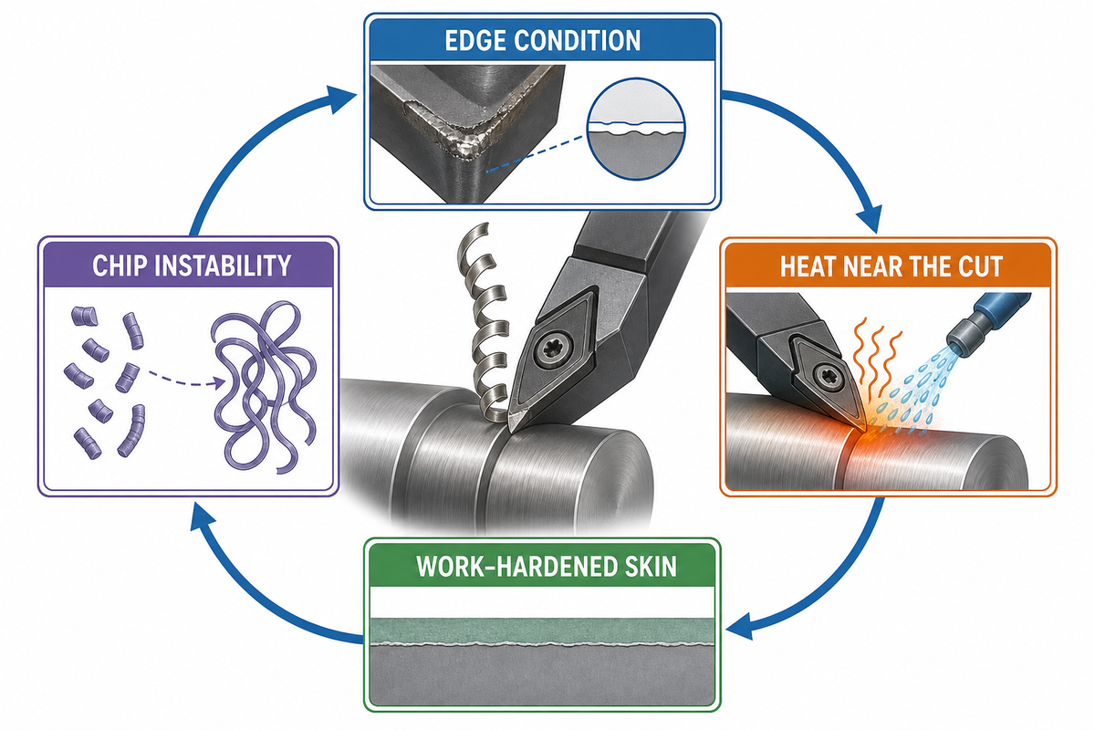
Stainless isn’t difficult because of one property. Low thermal conductivity in many grades, strain hardening, ductile chip behavior, adhesion at the edge, and relatively high cutting forces can reinforce one another. The practical result is a feedback loop: an unstable cut changes the surface that the next edge engagement must cut.
Heat-Hardening-Chip Feedback Loop
- The edge loses a clean shearing action through wear, dwell, inadequate engagement, or deflection.
- More energy stays near the edge and workpiece surface instead of leaving in a controlled chip.
- Adhesion, built-up edge, or a work-hardened skin increases the load on the next engagement.
- The changed edge and surface disturb chip formation, which adds more heat and instability.
This 4-step loop is an editorial synthesis of producer, association, and trade guidance. It’s a diagnostic model, not a claim that every failed cut follows the same sequence.
Outokumpu’s manufacturer machining guidance explicitly treats grade properties, speed, feed, tool choice, cooling, and chip control as an interacting set. Because Outokumpu is a steel producer, its product-specific statements are attributed here; they aren’t independent validation or transferable settings.
The immediate operating question is therefore not “How hard is this grade?” It’s “What changed in the cut?” A shiny rubbed surface, a darker chip, a rising load, a changing sound, and a worn edge are different evidence surfaces. Reading them together is more useful than adjusting a parameter in isolation.
Key takeaway
Treat hardness as one input. The decisive question is whether the complete cutting system is still producing a repeatable chip without rubbing, recutting, thermal drift, or unstable load.
How Grade Family, Condition, and Operation Change the Decision
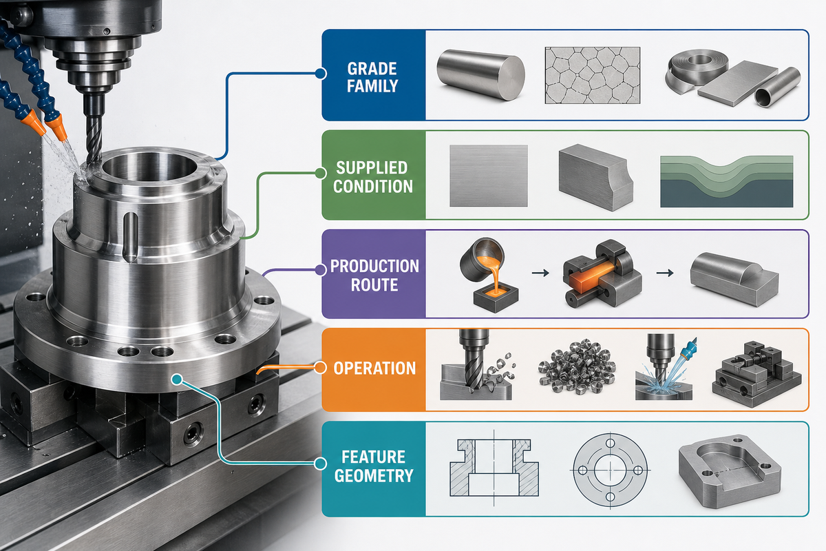
In practice, the system view narrows the next question: grade names don’t determine one recipe. Austenitic, ferritic, martensitic, duplex, and precipitation-hardening stainless families differ in strengthening mechanism, thermal behavior, ductility, and supplied condition. Within a family, product form, heat treatment, free-machining practice, and the operation can change what the tool experiences. For a supply-side product reference, review stainless steel materials from TiAlloy and request the exact grade, product form and condition before planning a machining trial.
| Material question | What it can change | What must travel with the answer |
|---|---|---|
| Family | Work-hardening tendency, ductility, thermal response, strength | Exact grade, product form, supplied condition |
| Free-machining variant | Chip breakability and edge behavior | Producer designation and corrosion or application tradeoff review |
| Heat treatment | Strength, microstructure, cutting-force response | Condition at machining, not only final material callout |
| Production route | Microstructure and local material history | Wrought, cast, additive, annealed, aged, or as-produced state |
| Operation | Engagement, chip space, heat path, tool stiffness | Turning, milling, drilling, tapping, slotting, and feature geometry |
Translate material and application labels into process facts
Search results often mix material, geometry, application, and procurement language. Start with the material layer. Stainless is a steel alloy whose chromium content supports corrosion resistance, but the label doesn’t say how a batch will cut. Austenitic stainless steel includes familiar designations such as stainless steel 304, while 201, 303, and 430 represent different compositions or families. Phrases such as good corrosion resistance, excellent corrosion resistance, superior corrosion resistance, heat resistance, high strength, formability, and resistance to oxidation describe selection goals. They don’t establish machinability or a valid cutting recipe.
Next define the geometry and operation. CNC milling with a carbide end mill creates a different engagement from drilling a deep hole or turning cylindrical steel parts. Sheet metal, a thick block, a thin wall, and a cylindrical feature send force and heat through different paths. A tool steel comparison can help explain edge demands, but tool steel and stainless steel alloys aren’t interchangeable workpiece categories. Any speeds and feeds recommendation must name the actual tool, holder, engagement, coolant path, machine state, and material condition used to remove material. Where the starting stock is tubular, steel pipe products from BalingSteel offer a product-range reference; confirm the supplied dimensions and condition against the machining drawing.
Finally, keep application labels in their place. Prototype, aerospace, automotive, and molding work can impose different records, edge conditions, cleanliness rules, or tight tolerances, yet none of those words diagnoses the cut. “Precision CNC,” “steel machining,” “surface finish,” “durability,” “steel parts,” “stainless steel parts,” “machined stainless steel,” and “machined stainless steel parts” are equally broad. A useful machining technique converts each label into a feature, function, material state, failure consequence, and measurable acceptance condition.
| Search-language cluster | Technical question it still leaves open |
|---|---|
| “common stainless steel,” “stainless steel grades,” “stainless steel 201,” “stainless steel 430,” “316 stainless,” and “304 is the most common” | Which exact designation, product form, condition, and certificate apply? |
| “corrosion resistance and formability,” “corrosion and oxidation,” “resistant to corrosion,” and “hard and soft” | Which property, test condition, service environment, and acceptance method are intended? |
| “stainless steel machining,” “precision CNC machining,” “working with stainless steel,” and “difficult to machine” | Which operation, engagement, edge, holder, coolant path, and material state produced the observation? |
| “milling steel,” “milling and turning,” “holes in steel,” “cylindrical parts,” and “sharp inside corners” | Which feature geometry, access, stiffness, chip space, and edge condition govern the cut? |
| “CNC machining projects,” “machining needs,” “manufacturing materials,” and “metal and plastic” | Which functional requirement belongs on the drawing or process record? |
| “machined parts,” “custom parts,” “metal parts,” and “steel components” | Which feature, datum, tolerance, surface, and released-part state will be inspected? |
| “precision CNC machined stainless steel,” “popular choice for CNC,” “used stainless steel,” and “carbon steels” | Is the phrase evidence, a comparison label, or only a broad search shortcut? |
For production availability and project-fit questions that sit outside this guide, use the separate stainless machining service page.
Why 304-versus-316 machinability claims need process context
There’s no context-free answer that should be converted directly into a shop setting. One commercial materials-distributor comparison table gives 304 and 316 the same reference-based machinability rating while listing different approximate speed guidance. That apparent contradiction is the lesson: the rating basis, tool system, condition, and operation must travel with the number.
Production route also resists simple ranking. In a bounded NIST 17-4 milling study, the tested wrought and additively manufactured states showed only minor cutting-coefficient differences, while annealing produced the stronger effect. That result belongs to those tested states; it shows why “additive versus wrought” can’t replace a condition-specific review.
Key takeaway
Use the grade family to choose questions, not to skip them. Record the exact material designation, product form, condition, route, operation, and feature before comparing machinability claims.
Building a Stable-Cut System for Tools, Chip Load, Heat, Coolant, and Workholding
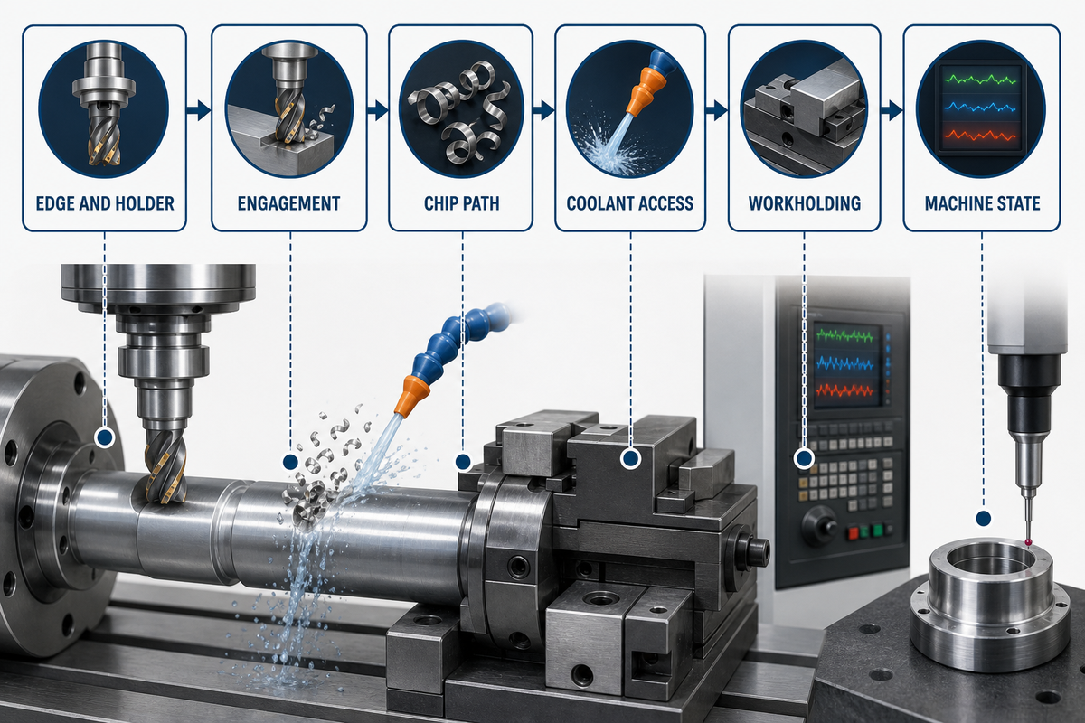
In turn, the material record becomes the starting point for stability: keep the edge in a repeatable cutting regime and give heat, chips, and force a controlled path out of the cut. The useful unit of analysis isn’t “speed” or “coolant.” It’s the complete chain from spindle and holder to edge, workpiece, fixture, chip space, fluid delivery, and measurement.
| Control point | Evidence of stability | Common misleading shortcut |
|---|---|---|
| Edge and holder | Consistent wear pattern, short overhang, controlled runout | Calling every edge failure “too much speed” |
| Engagement | Continuous chip formation without dwell or repeated light rubbing | Reducing feed until the edge stops cutting cleanly |
| Chip path | Chips leave the feature and do not recut or pack | Judging evacuation only at the machine door |
| Coolant access | The stream reaches the active edge throughout engagement | Assuming more volume helps when geometry blocks delivery |
| Workholding | Repeatable support with enough restraint but no avoidable distortion | Adding clamp force without checking released-part movement |
| Machine state | Thermal and load patterns are repeatable over the measured cycle | Comparing a cold first part with a stabilized sequence |
Why “use more coolant” can fail
Coolant performance depends on access and continuity. Shoulders, rotating chip masses, moving nozzles, deep features, and air barriers can keep a visible stream away from the edge. A 2017 CTE trade feature quoting several toolholder suppliers illustrates why delivery geometry matters alongside flow or pressure. Before changing concentration or volume, verify where the fluid goes during the actual engagement.
Why “slow it down” can fail
Lower speed may reduce heat in one stable process. It may also accompany dwelling, rubbing, built-up edge, or unstable chip formation in another. BSSA’s general machining principles emphasize maintaining cutting action and avoiding dwell. Inspect the edge, chip thickness, engagement, rigidity, and wear before treating speed as the cause.
Key takeaway
Change one cause class at a time. If edge, engagement, chip path, coolant access, restraint, and machine state are all moving together, the next trial teaches very little.
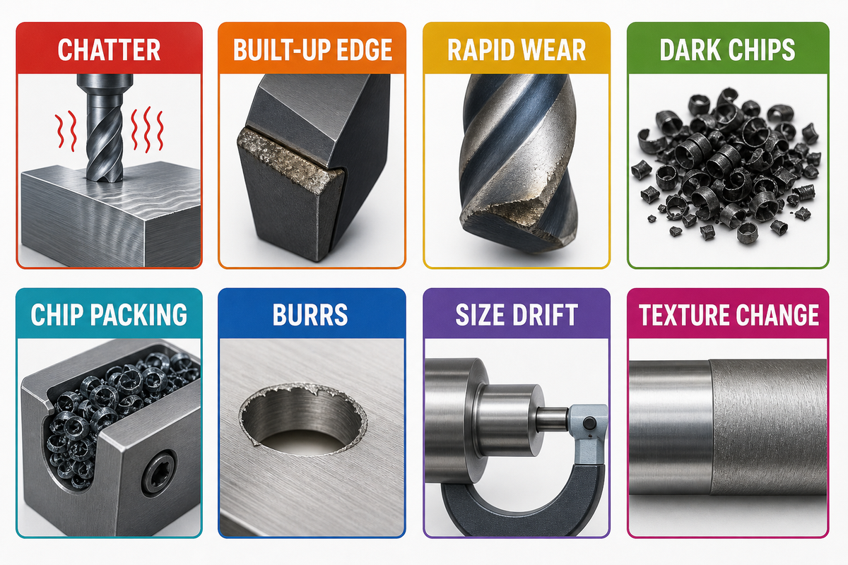
Eight Failure Signals and What to Inspect Next
Visible symptoms are not diagnoses. Chatter, burrs, dark chips, built-up edge, rapid wear, drift, poor texture, and chip packing each have several plausible causes. The fastest safe response is to preserve the evidence, identify the affected cause class, and then run a controlled change that can disprove a hypothesis.
Eight-Signal Stainless Machining Diagnostic
The matrix below packages evidence from NIST measurement context, BSSA, CTE, peer-reviewed machining studies, and practitioner problem language. It doesn’t convert one symptom into one guaranteed correction.
| Signal | Plausible cause classes | Inspect before changing parameters |
|---|---|---|
| 1. Chatter or tonal change | Overhang, support, runout, wear, interrupted engagement, previous hardened pass | Tool and part frequency clues, holder marks, edge image, stock left by the prior pass |
| 2. Built-up edge | Adhesion, edge temperature, geometry, unstable chip flow, worn coating or edge | Deposited material, chip underside, wear location, coolant contact point |
| 3. Notch or rapid flank wear | Hardened entry line, scale, chip recutting, thermal cycling, local interruption | Wear location versus depth line, entry/exit state, chip path, coolant continuity |
| 4. Dark or inconsistent chips | Heat concentration, changing engagement, blocked evacuation, edge deterioration | Chip sequence by feature position, load trend, edge state, coolant access |
| 5. Long chips or chip packing | Chip-break mismatch, inadequate space, feature depth, ductility, delivery direction | Where the chip stops, whether it recuts, tool flute or breaker loading, exit path |
| 6. Burrs or damaged edges | Edge wear, exit support, deflection, ductile rollover, cross-hole intersection | Burr direction and location, local edge requirement, exit geometry, tool condition |
| 7. Size or form drift | Tool deflection, thermal state, clamping, wear, datum shift, residual-stress release | Part temperature, clamp/release state, tool offset history, datum and method |
| 8. Roughness or waviness change | Chatter, built-up edge, feed marks, measurement direction, filter or cutoff mismatch | Profile direction, evaluation settings, edge image, vibration and part state |
Built-up edge is a signal, not an automatic reject. In one controlled wet AISI 304 turning study, the outcome changed with built-up-edge stability: unstable fragments damaged the surface, while a thin or stable adhesion layer could reduce friction or protect the surface under those test conditions. The reported trial used 60 m/min, 0.1 mm/rev, and a 0.5 mm depth of cut; those values describe the experiment and are not recommendations. Treat this condition-bound result as a counterexample, not a target setting.
The matrix deliberately includes local edge condition. A face can meet size and roughness requirements while a cross-hole, thin-wall exit, sealing edge, or sharp feature carries a functionally significant burr. Burr acceptance needs its own location, direction, maximum-condition language, and inspection method when function depends on the edge.
Use a 3-step trial discipline: freeze the current evidence, state one falsifiable cause, and change one controllable class. “Replace the edge and preserve every other variable” teaches more than changing tool, speed, feed, coolant, and clamping together. If the symptom remains, the failed hypothesis is useful data.
Key takeaway
Don’t correct the noun. Correct the mechanism. “Chatter,” “burr,” and “drift” name observations; the evidence chain must still distinguish edge, engagement, chip, heat, support, material state, and measurement.
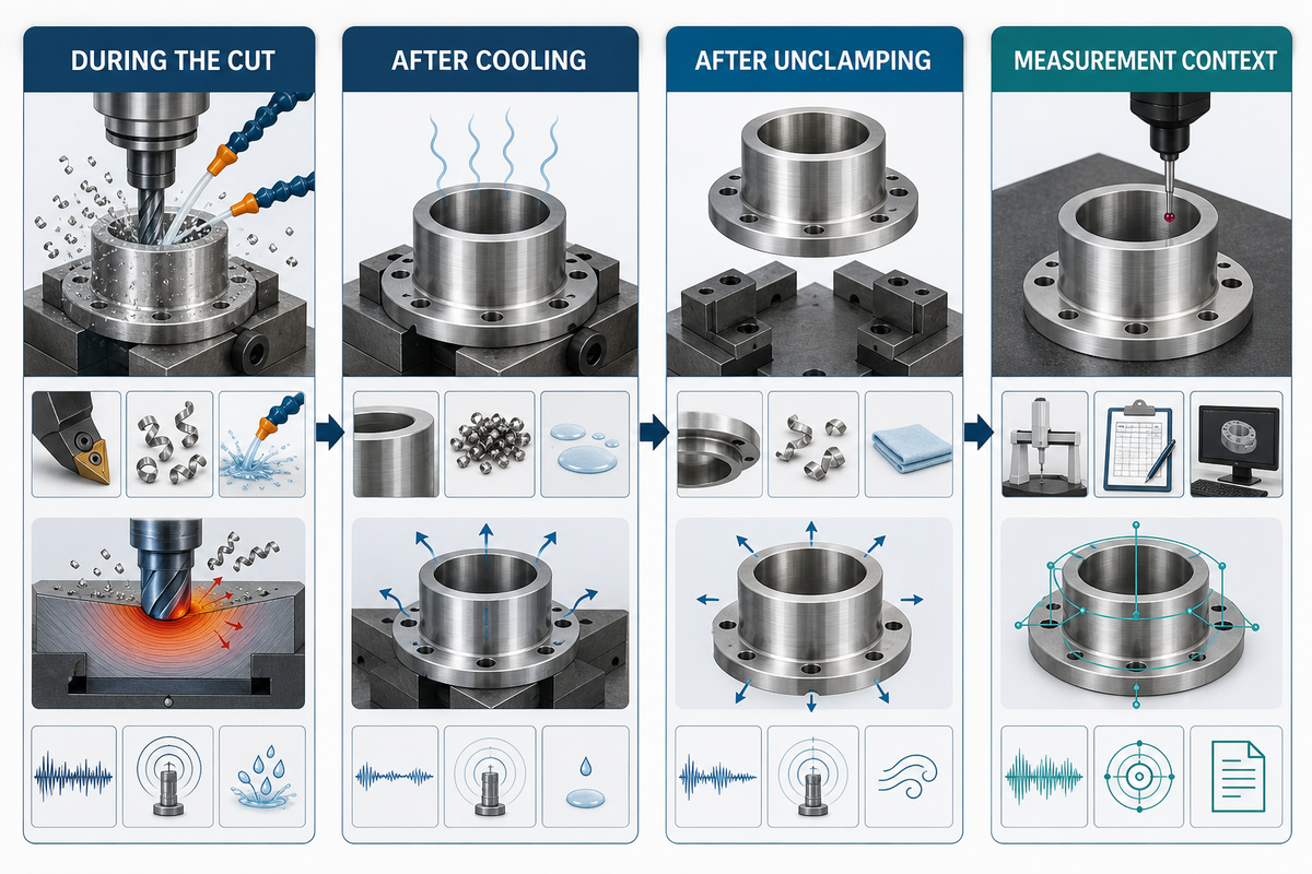
Why Dimensions Move After Cutting, Cooling, or Unclamping
Dimensional movement can come from elastic cutting deflection, thermal growth, fixture restraint, datum or method change, tool wear, or residual-stress redistribution. Timing and part state provide the first diagnostic split. Values measured hot and clamped aren’t the same evidence as the same feature measured cool and released.
“Only measurement results are traceable.”
If an indicator resolves to 0.001 mm, keep the trial record in that same unit. The value describes the measurement system; it does not establish an acceptable machining tolerance.
| When the change appears | First hypotheses | Evidence to preserve |
|---|---|---|
| During the cut | Tool or part deflection, unstable load, support | Load trend, toolpath position, in-process measure, support map |
| After the part cools | Thermal state, machine stabilization, measurement environment | Part and environment temperature, elapsed time, sequence position |
| After unclamping | Fixture restraint, elastic recovery, residual-stress redistribution | Clamping map, released measurement, stock-removal symmetry |
| Between inspectors or instruments | Datum, alignment, method, filter, uncertainty, reporting | Measurand definition, setup, instrument state, result and uncertainty |
For thin walls or strongly asymmetric stock removal, residual-stress release deserves early attention, but it isn’t proven by movement alone. An open-repository AISI 304 turning study measured machining-dependent residual stresses and discusses dimensional change. Its values remain bound to the tested specimens and conditions; this guide uses the mechanism boundary, not the reported stresses as a transferable prediction.
Use a 5-field record: the feature and datum, part temperature, restraint state, measurement method, and time in the process sequence. Add the stock-removal history when distortion is plausible. This doesn’t make every measurement comparable, but it prevents a team from discussing different physical states as though they were one result.
Key takeaway
Before changing the machining process, prove that the compared numbers describe the same feature, datum, temperature, restraint state, method, and sequence point.
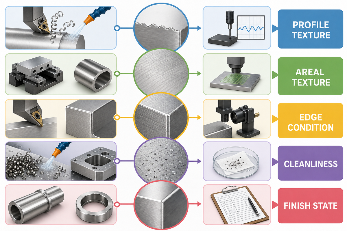
Surface Integrity Beyond One Roughness Value
In turn, the same-state comparison extends from dimensions to the surface: Ra is a useful profile parameter, not a certificate for the whole surface. Finished stainless parts may also need controls for waviness, directionality, local defects, burrs, altered hardness, residual stress, cleanliness, contaminant iron, and passivation acceptance. The drawing and inspection plan must say which question each measurement answers.
For metastable austenitic material, the plan may also need phase characterization. Neither Ra nor hardness alone establishes whether machining changed phase content, so add that test only when the supplied condition and functional risk make the distinction relevant.
Profile texture is not areal texture
ISO’s catalogue describes ISO 21920-2:2021 as a profile-method surface-texture standard. Separately, the published ISO 25178-2:2021 covers areal-method parameters. Those scopes are not interchangeable. When comparability matters, record measurement direction, filter or cutoff, sampling and evaluation length, instrument state, surface location, and part state.
| Acceptance layer | Question it answers | Example record |
|---|---|---|
| Geometry | Is size, form, or position acceptable? | Feature, datum, method, restraint and temperature |
| Profile texture | What does a defined line trace report? | Parameter, direction, filter/cutoff, evaluation length |
| Areal texture | What does a defined surface area report? | Areal parameter, area, method, processing settings |
| Edge condition | Are burrs, rollover, or sharp-edge requirements controlled? | Feature location, direction, limit and inspection method |
| Surface/subsurface state | Did machining alter hardness, stress, or microstructure? | Test method, location, depth and condition |
| Cleanliness and passivation | Is the required contaminant or treatment acceptance met? | Specified practice, selected procedure, test and purchaser criteria |
Roughness does not prove corrosion readiness
ASTM’s current A380/A380M-25 scope addresses cleaning, descaling, and passivation when contaminants may impair normal corrosion resistance, and it makes the selected procedures dependent on service needs and purchaser-supplier agreement. Therefore, a roughness result or visual finish does not establish cleanliness, free-iron condition, or passivation acceptance. This is a handoff boundary, not a passivation procedure.
The drawing-to-measurement handoff should carry at least 7 items when the surface is functionally important: feature/location, governing edition, parameter, direction or area, filter and length settings, part state, and acceptance method. Add cleanliness or passivation requirements as a separate line instead of hiding them inside “good finish.”
Key takeaway
Ask what a surface requirement is meant to protect: geometry, texture, edge function, subsurface state, cleanliness, or corrosion-service preparation. One metric can’t answer all 6 layers.
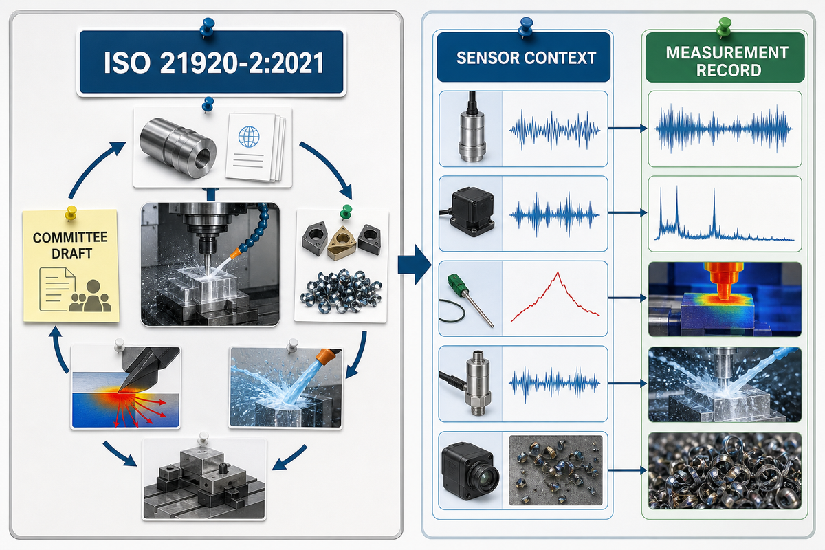
What to Verify in 2026: Standards Status and Connected Measurement
Meanwhile, current document status deserves a separate check. The practical 2026 change is not a new universal stainless-machining rule; it is a verification obligation. ISO lists the current profile-texture edition as published while a second edition remains under development. At the same time, connected measurement can combine more process signals, but the value still depends on context and interoperability.
Draft status, not an effective replacement
As of August 28, 2026, ISO 21920-2:2021 remains the published edition. ISO lists ISO/CD 21920-2 Edition 2 as a committee draft under development that is intended to replace it. Do not write “per the 2026 edition” unless a published edition and the project documents actually support that statement.
NIST’s on-machine measurement use cases provide a durable information framework, not evidence that every shop has a 2026 digital thread. A reviewed 2014 CTE example combined controller, cutting-force, and temperature data to monitor chatter conditions and tool wear, while also reporting interoperability limits at that time. The age and limitation matter: sensors can add evidence, but they don’t repair an undefined measurand or a broken data handoff.
- Name the standard and edition on the drawing or inspection plan.
- Separate published requirements from committee-draft awareness.
- Define the measurand, datum or coordinate context, part state, and method.
- Preserve raw or traceable process signals only when their source and timing remain identifiable.
- Use monitoring as evidence for a decision, not as an automatic claim of conformance.
Key takeaway
For 2026 projects, verify the published edition and the data context. Drafts are watch items, while sensor signals are observations; neither becomes a finished acceptance decision by itself.
Frequently Asked Questions
Those verification boundaries frame the recurring machining questions below.
What is the first sign that a stainless tool is rubbing instead of cutting?
No single symptom proves rubbing. A rising load, heat without a proportional chip, smeared material, changing sound, or rapid edge deterioration should trigger a combined check of chip thickness, engagement, edge condition, runout, and dwell. Compare the current chip and load pattern with a known stable interval before changing speed or feed. The diagnosis becomes stronger when several signals move together and weaker when it relies on sound or surface appearance alone.
Why does stainless steel work harden during machining?
Plastic deformation near the cutting zone can raise local strength. Dwell, rubbing, a worn edge, unstable engagement, or repeated light passes may leave the next engagement facing a changed surface. Diagnose the cutting action rather than treating “work hardening” as a complete root cause. Check chip formation, edge wear, sound, and load together, because a changed surface can also be the consequence of deflection, heat concentration, or repeated recutting rather than one isolated setting.
How can a shop separate tool wear from part movement?
Track the same feature through the cutting cycle, fixture release, cooling interval, and repeat measurement. Tool wear often follows edge history, load, chip form, and position in the run; part movement follows restraint, temperature, stock-removal sequence, support, and elapsed time. Change one cause class at a time and preserve the part state with each result. A single end-of-cycle dimension cannot separate these paths.
Does a lower Ra mean a better stainless surface?
No. A lower Ra reports one defined profile result; it doesn’t prove areal texture, edge condition, cleanliness, passivation, or corrosion behavior. Confirm the parameter, direction, filter, evaluation length, surface location, and part state before comparing two results, then use the value only for that stated measurand.
What should be recorded when a stainless part changes size after unclamping?
Record the feature and datum, temperature, clamp and release state, measurement method, elapsed time, stock-removal sequence, support map, and tool-offset history. Those facts help separate thermal, elastic, restraint, wear, method, and residual-stress hypotheses before the team changes the cutting process.
Move From a Symptom to a Production Review
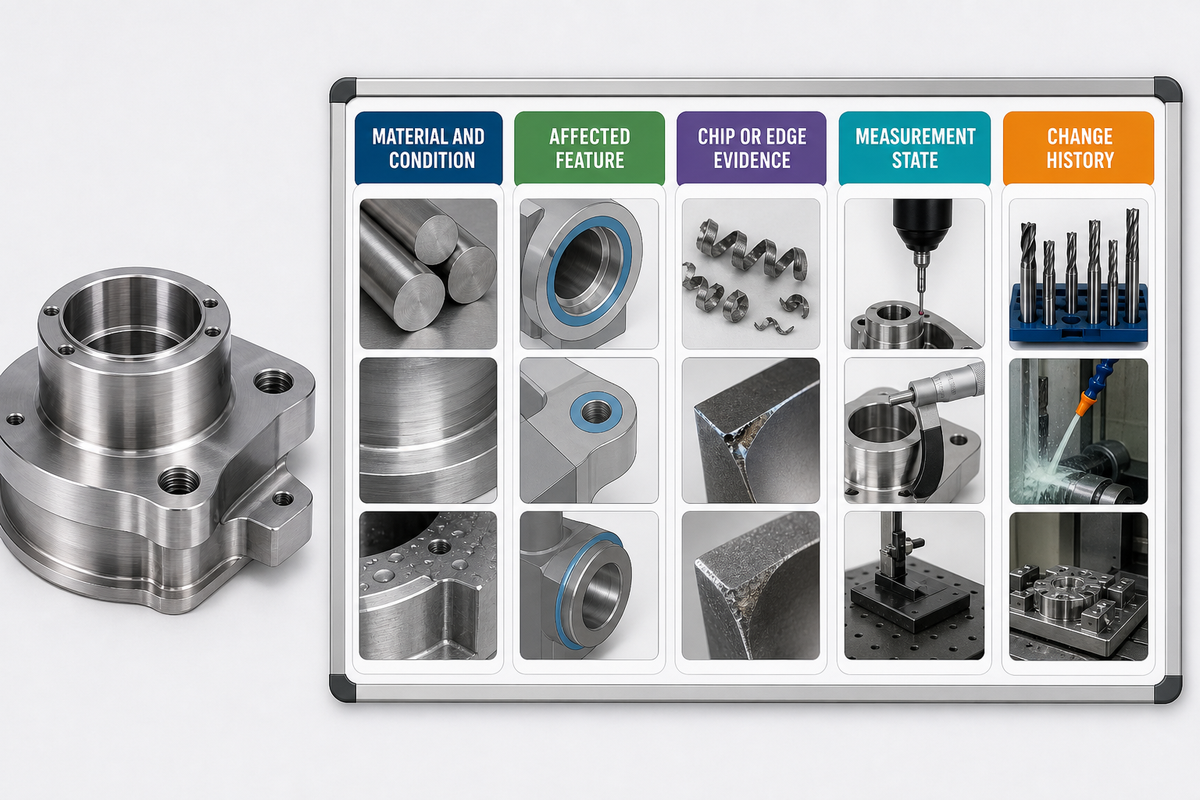
Bring the material designation and condition, drawing, affected feature, chip or edge evidence, measurement state, and the change history. That evidence gives Zhenling Metal’s manufacturing team a clearer starting point than a request for a universal speed or feed. You can also review the separate production service scope before opening the Blocksy contact form.
References & Sources
- NIST, On-machine measurement use cases and information for machining operations
- NIST, Metrological traceability
- ISO, ISO 21920-2:2021 profile surface-texture scope and status
- ISO, ISO/CD 21920-2 Edition 2 committee-draft status
- ISO, ISO 25178-2:2021 areal surface-texture scope
- ASTM International, A380/A380M-25 cleaning, contamination, and passivation scope
- NIST, Force modeling for hybrid manufacturing
- Balıkesir University repository, AISI 304 machining residual-stress study
- British Stainless Steel Association, General principles of machining stainless steels
- Cutting Tool Engineering, Machining stainless steel
- Cutting Tool Engineering, Chatter monitoring with controller and sensor data
This article is an evidence-bounded editorial guide from Zhenling Metal. It doesn’t replace a material certificate, licensed standard, drawing review, controlled test cut, or application-specific inspection plan.