Get in touch with Zhenling Company

How to machine alloy steel is a drawing-first planning process: first lock four inputs, the governing material identity, supplied and metallurgical state, feature risk, and the operation with its acceptance boundary. Only then should you select tooling, set a qualified starting window, run a controlled cut, and adjust from heat, chips, edge wear, and inspection evidence.
Updated August 2026
The short version
- Confirm the material specification, condition, hardness evidence, and any cross-standard boundary.
- Choose the treatment and finishing route before releasing stock.
- Assign each feature to an operation, then test source-qualified cutting data one variable at a time.
- Link workholding, movement risk, finishing, and inspection to every critical feature.
A familiar grade name isn’t a cutting plan. Machinability depends on the material and its microstructure, inclusions, hardness, operation, tool system, geometry, and cutting conditions, as discussed in a peer-reviewed machinability review and a peer-reviewed review of steel inclusions and machinability. This guide turns those variables into a drawing-first planning method; it isn’t a universal parameter chart.
This guide treats alloy steel as the workpiece family. Stainless steel is another type of steel and requires its own material- and condition-specific cutting data.
Is Alloy Steel Machinable? Start with Four Locked Inputs
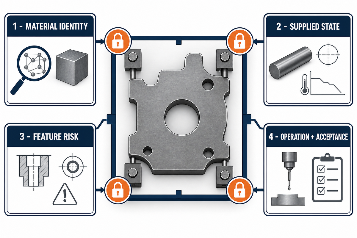
Yes, alloy steel is machinable, but the family label doesn’t predict one cutting response. Two parts described as “alloy steel” can behave differently because their standards, delivery conditions, heat histories, hardness levels, microstructures, inclusions, section sizes, and features are different; a peer-reviewed review of steel inclusions and machinability illustrates why composition alone is not enough.
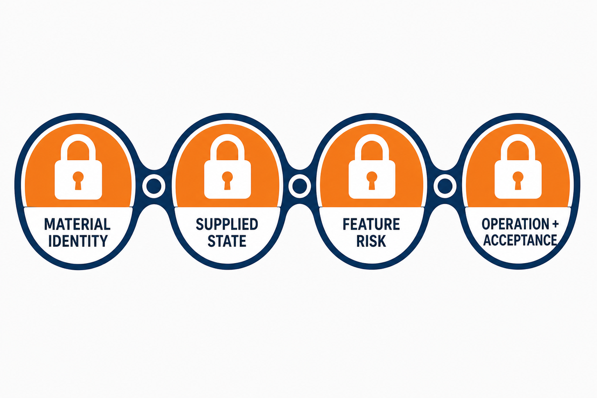
Apply the 4-Block Release Rule before discussing a cutter or cutting value. Release planning only after the material identity, supplied state, feature risk, and operation-and-acceptance block are recorded; otherwise, keep the missing block open instead of filling it with a familiar shop rule.
| Lock | Record before planning | Why it changes the route |
|---|---|---|
| 1. Material identity | Grade, governing standard, product form, heat/lot traceability | A trade name or grade number alone may hide a different specification basis. |
| 2. Supplied state | Delivery condition, prior treatment, measured hardness, microstructure evidence when relevant | Annealed, normalized, quenched-and-tempered, case-treated, and through-hardened stock do not present the same cutting problem. |
| 3. Feature risk | Thin walls, deep holes, interrupted cuts, long reach, critical radii, functional surfaces | Geometry determines access, deflection, chip evacuation, heat concentration, and movement risk. |
| 4. Operation and acceptance | Machine, process, tool, engagement, coolant, workholding, datums, tolerances, inspection, and service requirements | Turning evidence does not transfer automatically to another operation, and dimensional conformance alone does not prove safety-critical suitability. |
Step 1: Confirm Grade, Standard, Condition, and Hardness
Treat this material line as incomplete: “4140 alloy steel.” A machinable purchase and process description normally needs the governing standard, product form, delivery condition, any prior or planned heat treatment, hardness requirement and measurement basis, and traceability expectation.
A standard also has a scope. For example, ISO 683-2:2016 covers alloy steels for quenching and tempering in specified product forms and conditions; citing that document is not the same as identifying an AISI/SAE grade or proving interchangeability.
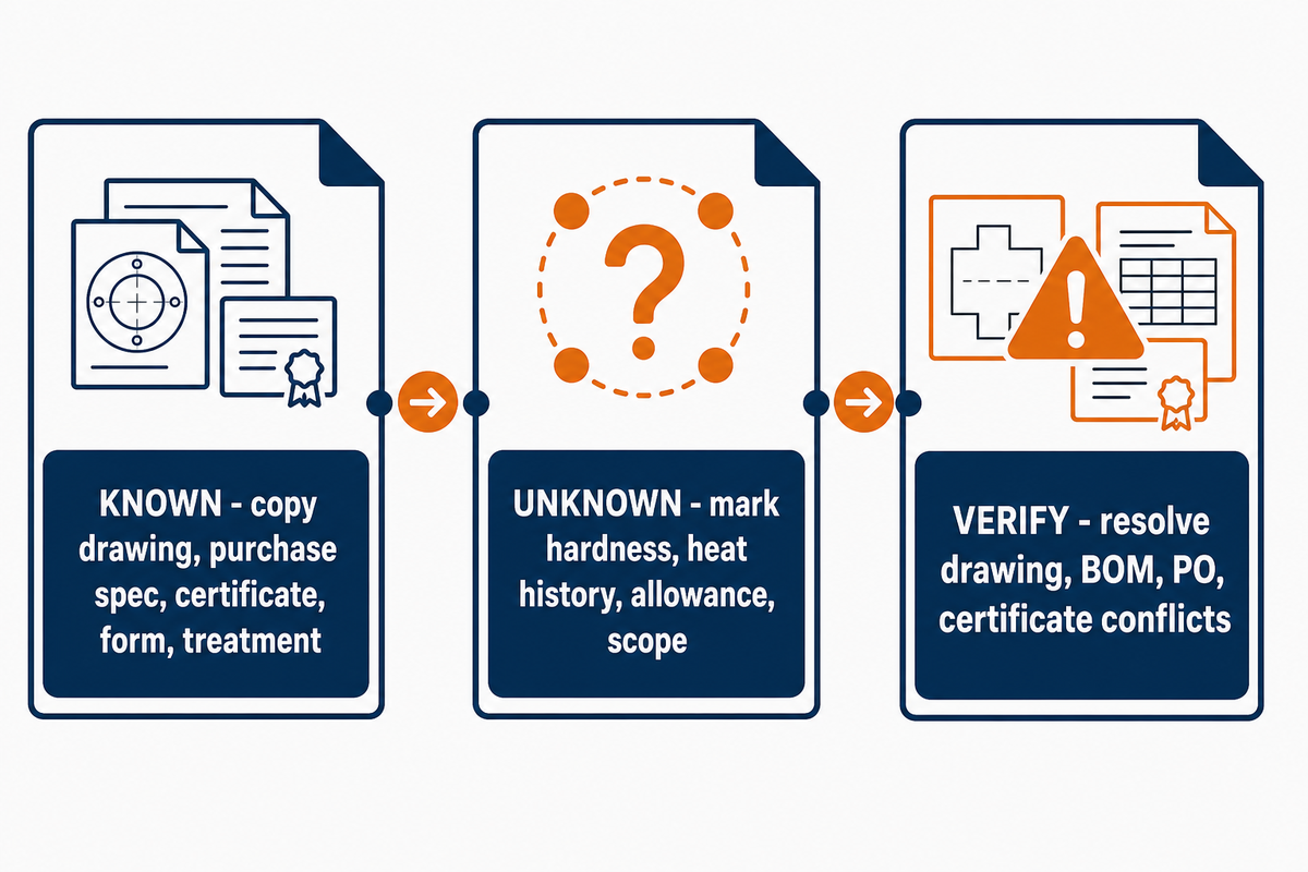
Known / unknown / must verify
- Known: copy exact drawing, purchase specification, certificate, product form, and treatment wording.
- Unknown: mark missing hardness, heat history, stock allowance, or certification scope openly.
- Must verify: resolve conflicts between the drawing, bill of materials, purchase order, and certificate before programming.
Measured hardness is important, but it can’t describe the whole metallurgical state. Carbon content and alloying elements such as chromium, molybdenum, and nickel influence hardenability and ductility. That decision cannot be borrowed from carbon steel such as 1018, cast iron, tool steels, stainless steel alloys, or aluminum alloys; those different types of steel and other metals and alloys can differ in alloy composition, mechanical properties, corrosion resistance, wear resistance, impact resistance, fatigue strength, and strength and toughness. Even within ferrous material choices, phosphorus and sulfur limits matter, so a common steel name is not a complete certificate.
Alloy machining for steel parts cannot start from a broad steel material label: search labels such as “alloy steel 4140” and “metal alloys” identify a topic, not a procurement definition. In aerospace and pressure equipment, the alloys used, strength and resistance targets, cutting fluid controls, and application-specific factors to consider belong in the route review. This rule also applies when metal machining searches surface free machining steel grades; chip-forming behavior is not permission to replace the alloy specified on a drawing.
Record the hardness test method and sampling location. After cross-sectional testing of three bars, a 2026 42CrMo4 hard-turning study reported 35 ± 1 HRC across its selected 38–68 mm diameter range. Its authors excluded smaller diameters from machining tests after observing a loss of hardness uniformity; that sampling decision does not establish a general section-size law. It does show why a single scalar hardness value can hide section-dependent behavior.
Step 2: Compare 4140, 4340, and 42CrMo Without Assuming Equivalence
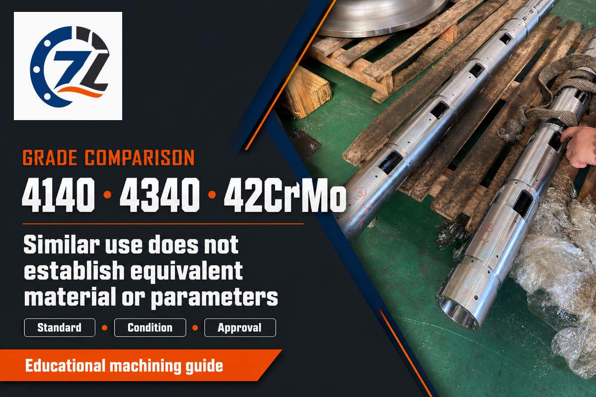
Do not give 4140, 4340, and 42CrMo one specification or parameter sheet merely because their uses overlap. Compare each against its governing standard, product form, condition, hardness, certificate requirements, geometry, and final service definition.
| Label | Useful planning question | Do not infer | Evidence still needed |
|---|---|---|---|
| 4140 | Which AISI/SAE, ASTM, AMS, or other requirement governs, and in what condition? | One hardness, chemistry, or cutting range for every product. | Certificate, condition, hardness, feature and acceptance data. |
| 4340 | Does the specified condition and section size produce the required property basis? | A 4140 process transfers unchanged. | Same fields, followed by a qualified trial where risk warrants. |
| 42CrMo | Which national or customer standard defines the designation? | Automatic equivalence to 4140 or 42CrMo4. | Exact specification, edition, condition, certificate and substitution approval. |
Technical literature may call two designations counterparts or even equivalents within a defined experiment. In the cited 2026 study, the authors describe hot-rolled 42CrMo4 to EN 10083-3 as equivalent to AISI 4140 to ASTM A29 for that material context. That wording does not create unconditional purchase-order interchangeability.
Similar chemistry bands or familiar applications may appear in a comparison, yet substitution still requires the governing standard and edition, product form, delivery condition, chemistry and mechanical requirements, dimensions, inspection, certification, and responsible approval. The official ISO 683-2:2016 scope is one example of why product form and delivery condition remain attached to a designation. If the specified grade is uncertain, review broader machining material options before narrowing the process route.
Is 4140 alloy steel easy to machine?
Machinability depends on condition and operation. Annealed 4140 can be approached very differently from prehardened or hard-turned stock, while a stable external turning cut differs from a deep hole or thin-wall feature. Tool material, coating, edge preparation, engagement, coolant delivery, rigidity, and acceptance finish also matter. Describe 4140 as conditionally machinable, then qualify the condition and feature before calling it easy or difficult.
Step 3: Choose the Rough–Treat–Finish Route Before Cutting
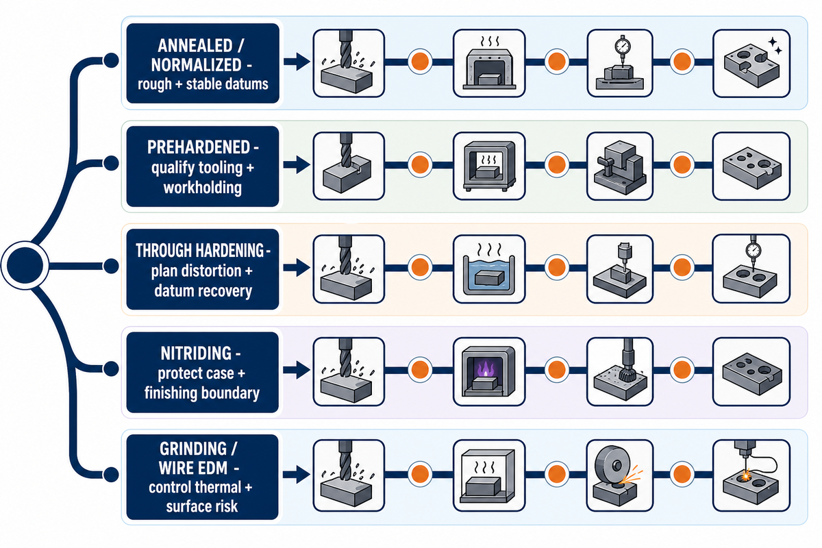
Decide the Rough-Treat-Finish Route Map before stock is removed. Map the datums, roughing sequence, protected features, treatment state, movement risk, finish stock, final process, and inspection stage. A published AISI 9310 gear route is one condition-bound example of rough machining, treatment, grinding, finish machining, and inspection—not a universal sequence.
Route map
- Machining in an annealed or normalized state: rough and establish stable datums; retain drawing-specific stock for treatment movement and finishing.
- Machining prehardened stock: qualify tooling and workholding for the actual hardness and feature engagement.
- Through hardening after roughing: define distortion risk, datum recovery, and final turning or grinding before heat treatment.
- Nitriding or another surface treatment: protect the case requirement and decide which surfaces may be finished afterward.
- Grinding or wire EDM: use them where access, hardness, finish, or geometry justifies the process; control their own thermal and surface risks.
There’s no detached “leave this much” allowance that fits every part. Section changes, length-to-diameter ratio, residual stress in the stock, treatment cycle, quench severity, support strategy, and final tolerance all influence the allowance and sequence. Nor is rough–treat–finish universal: some nitriding routes occur after final machining and may need no post-treatment machining, while other routes require deliberate stock for hard finishing.
Step 4: Match Turning, Milling, Drilling, Grinding, or EDM to Geometry

Choose the operation feature by feature. Bar, forging, or plate stock, interrupted engagement, tool reach, wall thickness, hole depth, chip exit, datum access, hardness, and final surface requirement matter more than a general statement that the part is “CNC machined.” High cutting forces may increase deflection or fixture demand, so the machining strategy must include work support rather than tool choice alone.
| Feature or need | Candidate process | Limitation to flag | Next verification |
|---|---|---|---|
| Shaft diameters and faces | Turning | Slenderness, interrupted shoulders, runout, chucking force | Support, datum sequence, insert data for the actual steel state |
| Pockets, flats and indexed faces | Milling | Entry shock, radial engagement, thin floors, tool overhang | Toolpath, fixture support, milling-specific cutter data |
| Deep or intersecting holes | Drilling, boring or reaming | Chip packing, drift, coolant access, exit burr | Pilot strategy, chip evacuation and bore inspection |
| Hardened datum or close final surface | Finish turning or grinding | Thermal damage and hidden surface-integrity changes | Wheel or tool specification, dressing, thermal control, required NDE |
| Hard, narrow or difficult-access contour | Wire EDM | Conductive workpiece, start-hole/access needs, recast layer, stress release | Electrical conductivity, surface requirement, trim-pass plan and inspection |
| External or internal thread | Thread turning, milling, or tapping | Tool exit, root form, burr, and post-treatment movement | Thread standard, gauge plan, treatment sequence |
| Thin web with cross holes | Indexed milling and drilling | Clamp distortion, breakout burr, interrupted engagement | Support state, toolpath order, released-part inspection |
| Close hardened bore or seat | Finish boring, honing, or grinding | Access, thermal damage, form, and surface function | Process trial and drawing-defined form/finish evidence |
For CNC turning on a lathe or CNC milling, match the right tool to the work material, engagement, metal removal path, and depth of cut. Carbide may suit a stable cut, while abrasion, hardened materials, or interrupted load can accelerate tool wear and make a feature difficult to machine; machine operators should change one variable at a time and record surface feet per minute. Toolmaker guidance for turning different materials is valuable within its stated context but shouldn’t be copied unchanged into milling or drilling. Seco’s toolmaker example treats high-speed steel cutters as a cutting-tool option for defined work materials and machine conditions, not as an alloy-steel workpiece grade or a universal choice. Likewise, EDM requires an electrically conducting workpiece and can create its own recast layer, heat-affected zone, and residual-stress concerns. See Zhenling’s overview of custom machining processes only after the feature map identifies what each operation must achieve.
Step 5: Set a Starting Window, Then Read Heat, Chips, and Edge Wear
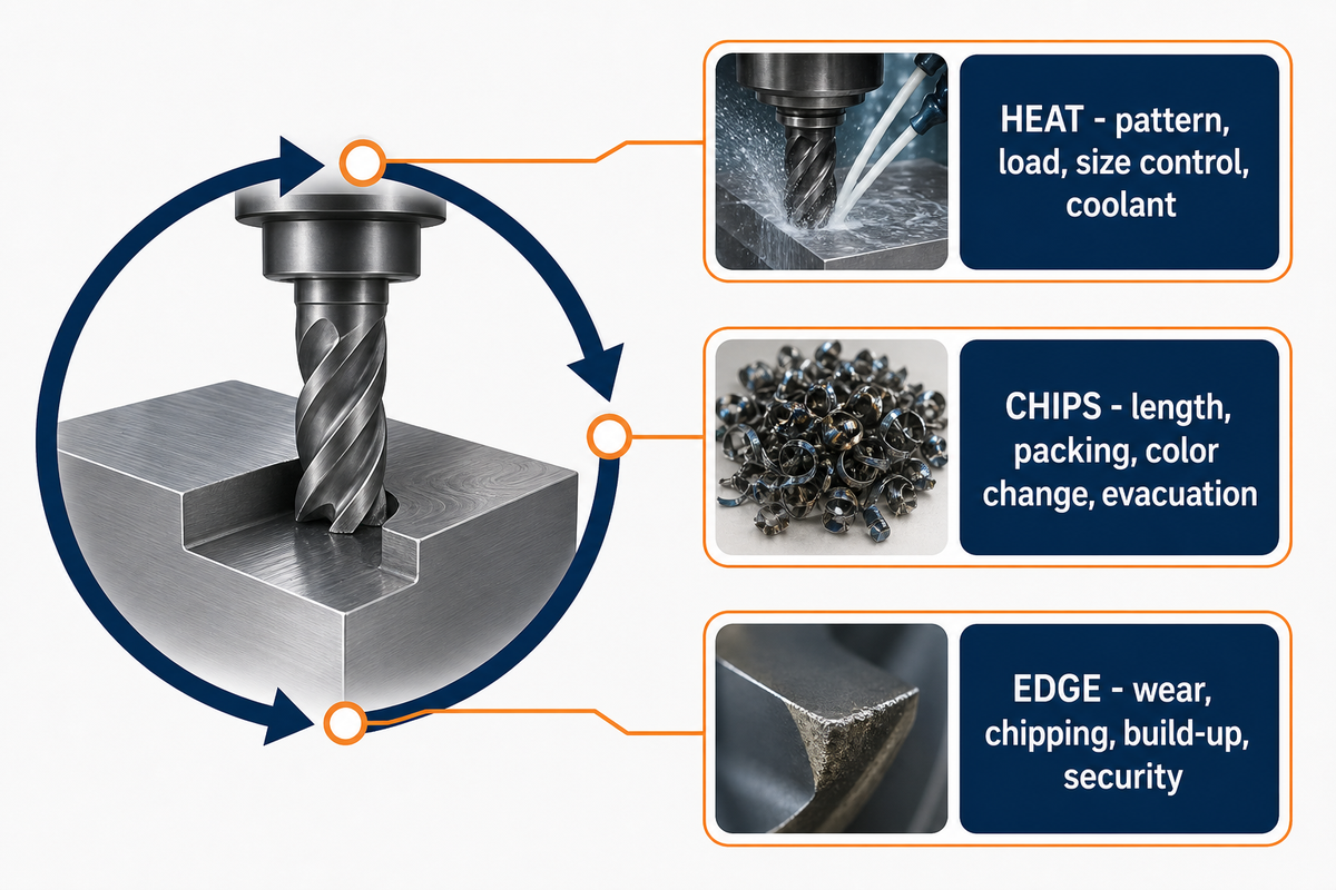
A starting speed or feed is qualified by grade, condition, hardness, operation, tool material, coating, edge geometry, engagement, coolant, machine power, and rigidity. Begin with data supplied for that combination, calculate spindle speed and feed correctly, then run a controlled first cut.
Starting-window method
- Record and qualify: capture the material, hardness, operation, tool, engagement, coolant, and source window.
- Check and cut: confirm rigidity, runout, support, coolant path, and chip exit before recording the first controlled result.
- Change one variable: preserve load, chip, edge, size, and finish evidence before the next adjustment.
A 2023 AISI 4140 hard-turning experiment shows why context must remain attached to numbers. Its 27 dry tests used a Ø110 mm × 600 mm workpiece and a specified coated insert with a 0.8 mm tip radius. The published matrix spans 90–150 m/min, 0.18–0.36 mm/rev, and 0.2–0.6 mm depths; these are experiment bounds, not recommendations. Detailed treatment and hardness metadata from that paper are not transferable targets; verify the actual material certificate, treatment record, and measured condition for the job.
| Published test-level category | Metric value | Arithmetic equivalent | Scope |
|---|---|---|---|
| Speed 1 | 90 m/min | 295 sfm | Experiment only |
| Speed 2 | 120 m/min | 394 sfm | Experiment only |
| Speed 3 | 150 m/min | 492 sfm | Experiment only |
| Feed 1 | 0.18 mm/rev | 0.0071 in/rev | Experiment only |
| Feed 2 | 0.27 mm/rev | 0.0106 in/rev | Experiment only |
| Feed 3 | 0.36 mm/rev | 0.0142 in/rev | Experiment only |
| Depth 1 | 0.2 mm | 0.0079 in | Experiment only |
| Depth 2 | 0.4 mm | 0.0157 in | Experiment only |
| Depth 3 | 0.6 mm | 0.0236 in | Experiment only |
Worked spindle-speed example
For a hypothetical 50 mm turning diameter, using the study’s 120 m/min test level only as an arithmetic input:
rpm = (1,000 × 120) ÷ (π × 50) ≈ 764 rpm
This calculation doesn’t recommend 764 rpm for another part. First match the grade, reported heat-treated condition, hard-turning operation, insert, dry environment, engagement, machine, and acceptance target, or return to qualified data for the actual job.
3-Channel First-Cut Rule
Heat: look for a changing thermal pattern, rising load, loss of size control, or coolant delivery failure, not color alone.
Chips: note length, segmentation, packing, color change, evacuation, and whether the chip strikes the work or tool.
Edge: inspect flank wear, crater wear, chipping, built-up material, notch wear, and edge security at planned intervals.
Thermal observation can reveal process change, but ordinary chip color or a clean-looking edge isn’t proof of temperature or subsurface integrity. The readback is a process-control method, not a metallurgical acceptance test.
Keep coolant performance separate from worker protection. NIOSH metalworking-fluid guidance notes inhalation and skin-contact exposure routes and that in-use water-based fluids may accumulate process contaminants or microbial growth. Follow the product safety information and applicable workplace controls for fluid maintenance, mist, splash, handling, and ventilation; this guide isn’t a site-specific exposure assessment.
Step 6: Plan Workholding, Distortion Allowance, Surface Finish, and Inspection
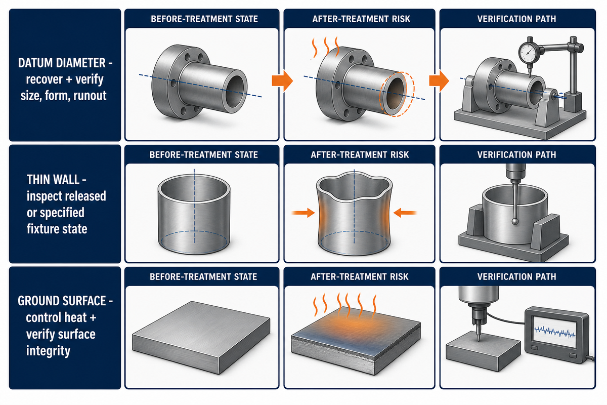
Connect every critical dimension or surface to its setup state, treatment stage, finishing route, datum, measurement method, and required record. A hypothetical ±0.01 mm limit is interpretable only after the datum, measurement method, and thermal state are defined. Thin walls may deflect under clamping; long shafts may move when residual stress is released; heat treatment may change form; finishing may create a surface that meets size but not the functional surface condition.
| Critical item | Before treatment | After treatment | Verify by |
|---|---|---|---|
| Datum diameter | Establish support and retain planned finish stock | Recover final datum without masking movement | Drawing-defined size, form, and runout method |
| Thin wall | Balance stock and clamping force | Measure released or specified fixture state | Defined restraint and temperature condition |
| Functional ground surface | Protect geometry and retain justified stock | Control grinding heat and dressing | Size/finish plus specified surface-integrity examination |
Define measurement state as well as method. NIST precision-length guidance corrects dimensions to 20 °C and shows that a 0.1 °C temperature uncertainty for steel can correspond to about 1.15 µm per metre. For tolerances where that contribution matters, stabilize the part and define the inspection temperature rather than comparing a warm part with a stabilized one.
A review of machined surface integrity distinguishes surface topography from changes such as residual stress, microhardness, and microstructural alteration. Arithmetic roughness and dimensional conformance alone may therefore be insufficient when fatigue or another functional requirement makes the subsurface condition critical.
Grinding or wire-EDM damage can remain hidden after a surface looks clean, so process heat and the affected layer need their own controls.
The caution is concrete: in a 2022 grinding-burn study, Sorsa and co-authors analyzed 42 burn locations in through-hardened L6 steel and reported that tensile residual stress could occur below a compressive surface; their background discussion also notes that temper burn need not be visible. This doesn’t establish a universal inspection method. The drawing, code, or quality plan must define whether residual stress, white layer, microhardness, microstructure, nondestructive examination, or other evidence is required.
Alloy Steel Machining Troubleshooting: Symptom to Next Check
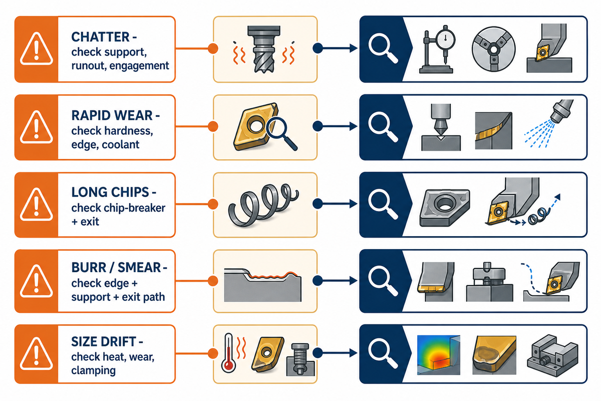
Troubleshoot from the observed signal and preserve the original baseline. Changing speed, feed, depth, coolant, tool geometry, and clamping together may hide the actual mechanism. The interaction among steel state and cutting conditions documented in this peer-reviewed machinability review is why the table starts with evidence rather than a universal correction.
| Symptom | Possible mechanism | First check | Next evidence |
|---|---|---|---|
| Chatter or repeating marks | Low dynamic stiffness, excess reach, unstable engagement | Holder, support, runout, clamping and engagement | Sound/load trend, measured finish, controlled variable change |
| Rapid flank or notch wear | Heat, abrasive state, work-hardened boundary, wrong edge application | Actual hardness, treatment, edge position and coolant path | Timed edge photos and toolmaker data for the exact operation |
| Long or packed chips | Chip-breaker mismatch, unsuitable feed/engagement, poor evacuation | Chip-breaker application window and chip exit | Chip samples after one qualified adjustment |
| Burr or smeared edge | Dull edge, support loss, unsuitable exit path | Edge condition and direction of tool exit | Burr location mapped to path and work support |
| Size drift or burnishing | Thermal growth, deflection, edge wear, insufficient cutting action | Part/tool temperature, wear interval and clamping state | Size-versus-time record at a defined inspection temperature |
Do
- Reconfirm the material state.
- Isolate the observed symptom.
- Preserve the baseline and inspect at a planned interval.
Don’t
- Do not apply a turning chart to milling.
- Do not declare a clean-looking surface metallurgically sound.
The Pre-Machining Worksheet: What Must Be Known Before CNC Starts
A filled worksheet is more useful than a speculative market outlook when the goal is a sound part plan. The research for this guide found no sufficiently supported current demand or standards driver for a forecast section, so this buyer-ready input sheet takes its place. The request for a governing standard, edition, product form, and condition follows the kind of defined scope shown on the official ISO 683-2:2016 record.
Pre-machining worksheet
- Drawing number and revision
- Governing material standard and edition
- Exact grade and product form
- Heat/lot and certificate requirement
- Supplied condition and prior treatment
- Required treatment and hardness basis
- Stock size and quantity
- Critical datums and functional surfaces
- Thin walls, deep holes, interruptions and reach
- Rough, treat–finish sequence
- Final process for each critical feature
- Surface-integrity requirements, if any
- Inspection method, record type, and defined inspection temperature where applicable—for example, 20 °C in the cited NIST guidance
- Applicable code, service and customer approvals
The worksheet doesn’t settle price, order minimum, lead time, supplier approval, or certificate scope. Those are commercial and project-specific questions that begin after the four locks are sufficiently defined.
Key takeaway
Lock four inputs before choosing a cutting value: material identity, supplied state, feature risk, and the operation with its acceptance boundary.
When General Guidance Ends and Drawing-Specific Review Begins
General guidance should stop when the next decision depends on the drawing, specification, actual material state, feature risk, quantity, treatment route, or acceptance evidence. At that point, move from an educational guide to a controlled manufacturability review rather than guessing from a generic chart.
According to information supplied by Zhenling, its material experience includes 25CrMo, 42CrMo, 12CrMoV, GCr15, Q235A, and Q345D. Zhenling also reports CNC turning, milling, grinding, boring, drilling, wire EDM, and 3-, 4-, and 5-axis machining centers, with a 6,000 m² workshop on an 8,000 m² site.
Zhenling reports application exposure to pressure-vessel, oil-gas-separation, and fluid-control components. These statements describe company-supplied context, not independently verified performance data; they do not establish a promised tolerance, lead time, application suitability, or pressure approval. Readers can learn more about Zhenling.
Machining feasibility and dimensional inspection don’t establish pressure-code conformity or suitability for high pressure, high temperature, corrosion, fatigue, or another safety-critical service. ASME’s nondestructive-examination overview distinguishes formal examination from ordinary dimensional and visual inspection within a wider conformity route.
The customer or responsible engineering authority must define the applicable code, design conditions, material specification, examinations, tests, approvals, and acceptance records. If those inputs are ready, check an alloy-steel part against its drawing or share the project inputs.
Frequently Asked Questions
Is alloy steel machinable?
Yes, but machinability is condition-dependent rather than a permanent rating for the entire family. Grade and chemistry, microstructure, supplied hardness, feature geometry, tool material, rigidity, coolant, and the acceptance target all affect the usable process window, as the variables surveyed in a peer-reviewed steel-machinability review help show. Before choosing a starting value, verify the four locks: material identity, supplied state, feature risk, and the operation with its acceptance boundary. Keep that record as the baseline for production comparisons and troubleshooting.
Is 4140 alloy steel easy to machine?
It depends on whether the stock is annealed, normalized, prehardened, or hardened, plus the operation and geometry. A 4140 label without its governing specification, condition, and measured hardness is insufficient. Use toolmaker data for the actual state, run a controlled first cut, and retain the certificate condition and hardness record so later tool-life comparisons refer to the same material basis.
What is the best steel alloy for machining?
There is no universal winner. Machinability must be balanced against strength, toughness, fatigue, wear, weldability, corrosion behavior, treatment response, and service requirements. A free-machining grade may form chips well yet be unsuitable for a critical application. Select the material from the governing specification and function first; then plan the process around the actual product form, condition, hardness, geometry, and required evidence.
Should alloy steel be machined before or after heat treatment?
Often both. Rough first when stock removal and later hardness justify it, protect datums, and leave a drawing-specific allowance. Then finish the functional features that require post-treatment control. Prehardened machining, nitriding after final machining, and hard finishing are counterexamples, so document the route instead of assuming one sequence.
Can one cutting-speed chart be used for 4140 and 4340?
Only as a starting reference when the specification, product form, condition, hardness, operation, tool, coating, engagement, coolant, and machine assumptions all match. If any input changes, return to grade- and operation-specific toolmaker data and run another documented trial. Don’t carry a 4140 result into 4340 merely because both are alloy steels or their applications overlap.
References & Sources
- Peer-reviewed review of steel machinability factors
- Peer-reviewed review of non-metallic inclusions and steel machinability
- ISO 683-2:2016 scope page
- AISI 4140 hard-turning experiment
- Sandvik Coromant material-specific turning guidance
- 2026 study of 42CrMo4 hardness distribution and hard turning
- Open University EDM process boundary
- NIOSH metalworking-fluid safety guidance
- NIST precision dimensional metrology guidance
- Peer-reviewed review of machined surface integrity
- Sorsa et al. grinding-burn and residual-stress study
- ASME nondestructive-examination overview
Editorial scope: This is process-planning education, not substitution approval, universal cutting data, an inspection specification, or a pressure-code decision. Company context is identified as information supplied by Zhenling.
![Shop-Floor Carbon Steel CNC Machining Guide [2026]](https://zhenlingmetal.com/wp-content/uploads/2026/08/carbon-steel-cnc-machining-handbook-r2-featured-150x150.png)