Get in touch with Zhenling Company

Polycarbonate CNC Machining Services
Polycarbonate CNC machining starts with a practical question: what must the finished part prove after machining, inspection and shipment? Zhenling reviews the CAD model, controlled drawing, grade, critical surfaces and acceptance evidence as one order plan. Polycarbonate CNC Machining enquiries should include grade, thickness, optical surface requirements, edge condition, stress-sensitive features and inspection. Confirm the order-specific route and measurement boundary in writing. Keep unresolved record or schedule assumptions visible.
- Quotation timing confirmed after RFQ review
- Prototype schedule confirmed in the quotation
- Minimum quantity confirmed in the quotation
- STEP, IGES, and dimensioned 2D drawings
Your files are handled as confidential, and a non-disclosure agreement is available on request before file review.

SYS_01 // RES
Quote response
Per quotation
SYS_02 // PRT
Prototype schedule
Per quotation
SYS_03 // VOL
Order floor
Per quotation
SYS_04 // CAD
File basis
STEP · IGES · 2D
SYS_05 // LOG
Delivery option
Incoterm confirmed per order
Polycarbonate CNC Machining Capabilities
Confirming that a CNC machine can cut plastic is only the starting point across plastic machining services. A drawing-to-release mismatch becomes a risk because stock history, fixture support, surface finish and inspection state interact. Review those factors before issuing the written quotation; a material name alone is not process approval for a machined part.
MILLING_01
CNC Milling from Plate or Block
Milling review covers pockets, bosses, slots, bolt holes, edge breaks, thin walls, broad faces, and datum access before setup selection. For complex parts, the aim isn’t the highest spindle speed or a generic feed rate; it’s stable support, controlled chip removal, and a release condition that matches the drawing.
TURNING_02
CNC Turning from Rod or Tube
Turning review covers wall section, chuck load, concentric features, bored diameters, threads, and cutoff edges. A sharp cutting tool and adequate chip evacuation matter because heat, recutting, and fixture pressure can change the edge or allow a thin feature to warp.
Part Families for Drawing Review
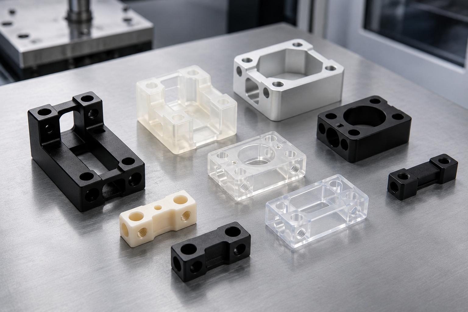
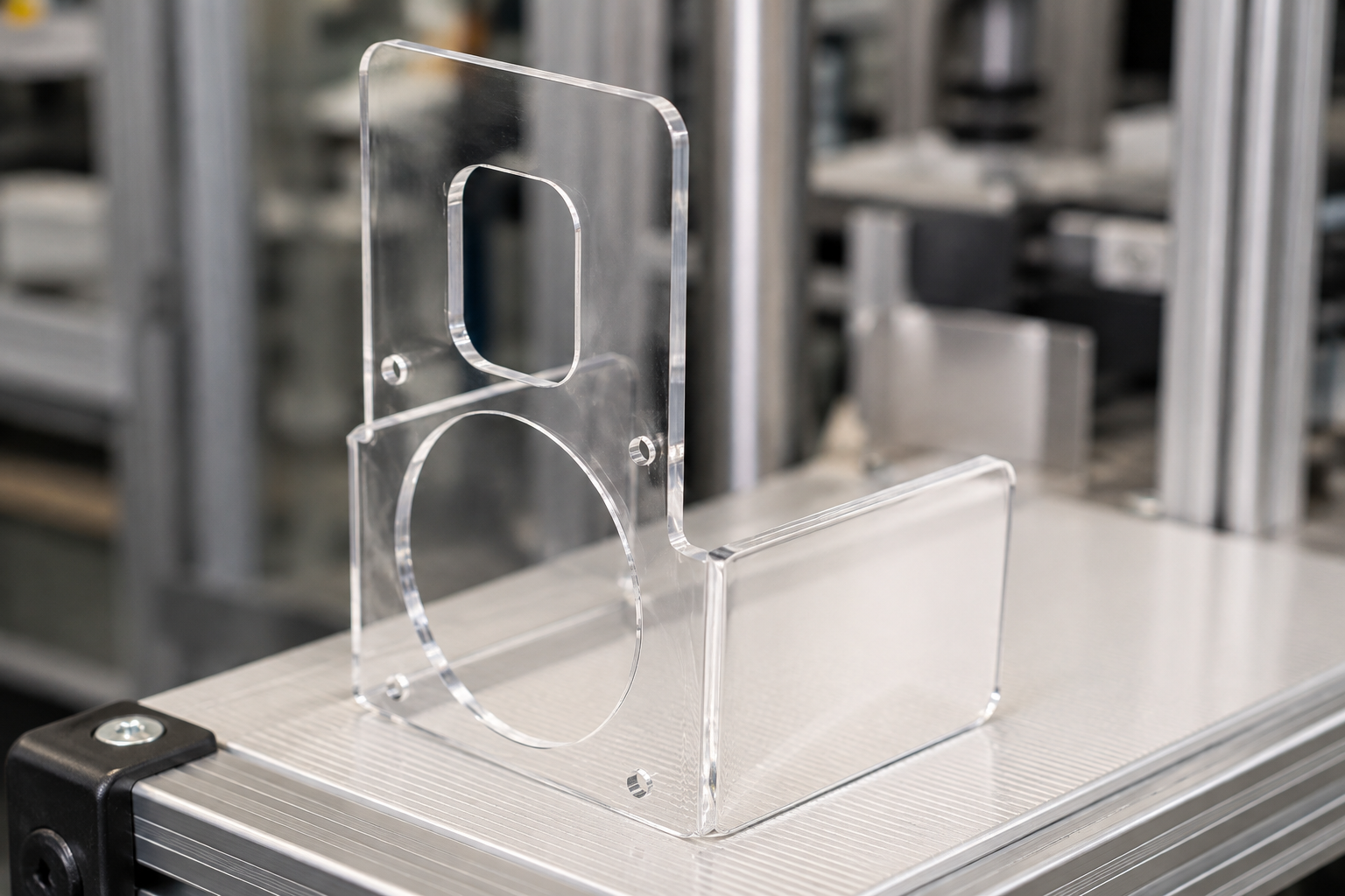
Protective covers, guards, windows and clear enclosure pieces with clearly labelled visual zones.
Electrical housings, lab apparatus or instrument cases with user defined grade and acceptance limitations.
Spacers, mounts, manifolds, brackets, panels, guides or custom made plastic pieces.
Prototype polycarbonate parts to confirm suitable form and fit, entry, and development prior to any production commitment.
Acrylic and polycarbonate parts viewed with respect to similar style, ecosystem, and appearance standards.
Cutting polycarbonate plates where fixture release, and protected surfaces identify acceptability, alongside minimum depth.
Precise pieces whose narrow tolerances only apply to assigned vital areas, rather than any surface area.
0xEVAL
Capability is drawing-specific
No universal size-and-tolerance range or blanket PC tolerance replaces a drawing review. Send the part model and dimensioned drawing; the quotation return accessible features, fixture risks, the inspection plan, and any requested drawing changes.
Two machining-service quotes are comparable only if they cover the same material callout, features, quantity, packaging, delivery envelope, and change assumptions. A lower price per piece may describe a materially different scope.
Check the four inputs that change the machining and release plan.
PC Grade and Stock Definition
A purchase document that states only “PC,” “Lexan” or “clear polycarbonate” is incomplete. Submit the exact resin grade, colour, additives, stock form and condition, dimensions, service environment and acceptance requirements. A family name cannot substitute for the specific material and process route reviewed for the order.
SEQ.01
Mechanical-Grade Route
ASTM D6098-25 classifies mechanical-grade extruded and compression-molded plate, rod, and tube. It expressly excludes glazing and signage, so the standard may identify stock-shape requirements without deciding an optical or glazing application.1
SEQ.02
Optical or Glazing Route
State the approved grade, transmission or image requirement, viewing zone, allowed tool marks, polishing state, coating need, and residual-stress test. “Optically clear” describes an outcome to measure, not a finish name that a machine shop can infer.
SEQ.03
Regulated End-Use Route
ASTM F997-18 explains that molding, extrusion, machining, assembly, and sterilization can alter material characteristics. Raw resin or stock evidence does not replace application-specific evaluation of the fabricated form.2

PARAMETERS
Six Material Inputs That Belong In The Request
-
Application route: mechanical-grade, optical/glazing, or regulated end use
-
Resin brand reference, specific grade, colour, or any rule outlining equivalent, authorized components
-
The beginning dimension for round, long and flat pieces or blocks, alongside the position of the customer supplied stock
-
Approval needs by the consumer, including: resistance to UV, flammability ratings, medical standard qualifications, aerospace or other standard qualifications, and the particular electrical standards required
-
Potential exposure to heat, moisture, any type of cleaning agent, gas, oil, any type of sealant, coating, or any load to which it will be exposed during an installation.
-
Lot identity, material certificate, substitution approval, and record-retention request
Why Stock History Stays In The Acceptance Discussion
Mitsubishi Chemical Advanced Materials identifies moisture, temperature, and internal stress as separate dimensional-stability mechanisms and notes that machining can add stress to a finished plastic part.4 That is why an RFQ should state where the component operates and how it is measured, not only the polymer name on the purchase order.
POLYCARBONATE // CNC
PC Acceptance Boundary Map
Do not apply one tolerance limit indiscriminately to every feature. The drawing should identify the controlling dimensions, datums, acceptance method and functional surfaces, while material behaviour, geometry and end use determine which process and inspection controls belong in the order plan.
Do not describe a clear part as optical unless the drawing names the optical measurement and acceptance method. Dimensional reports and visual checks answer different questions.
Decision Record Logbook
PARAMETER INDEX //
- 01 Application route
- 02 File basis
- 03 Material identity
- 04 Geometry risk
- 05 Surface class
- 06 Release evidence
- 07 Quote response
- 08 Prototype schedule
01
Application route
INPUT
Choose 1 of 3: mechanical, optical/glazing, regulated
WHY
Prevents a mechanical-grade standard from being extended to a different end use.
02
File basis
INPUT
1 controlled 3D model + 1 dimensioned 2D drawing
WHY
Separates geometry definition from dimensions, datums, notes, and acceptance.
03
Material identity
INPUT
1 exact grade + approved-equivalent rule
WHY
Keeps resin, filler, color, stock process, and qualification aligned.
04
Geometry risk
INPUT
Mark 4 conditions: thin, broad, long, sharp transition
WHY
Directs support, rough/finish planning, and inspection after fixture release.
05
Surface class
INPUT
Choose 1 of 3: functional, cosmetic, optical
WHY
Prevents “clear” from replacing a measurable acceptance method.
06
Release evidence
INPUT
Choose 1 of 3: drawing check, report/certificate, special test
WHY
Aligns the shipment record with the buyer’s approval responsibility.
07
Quote response
INPUT
Timing confirmed after RFQ review
WHY
Starts after usable files and requirements are received.
08
Prototype schedule
INPUT
Schedule confirmed in the quotation
WHY
Finishing and transit are quoted separately.
Three Outputs from the Review
Drawing Callouts
Material, datums, critical dimensions, surface zones, edge state, test method, and sampling are made explicit.
Machining Controls
We define stock orientation, support logic, cutting sequence, chip evacuation, thermal control, protected faces, and post-release inspection checkpoints.
Release Evidence
We identify the revision, material record, dimensional result, appearance approval, and any buyer-owned optical or regulated qualification.
Build a drawing-specific list before sending the request.
Run the interactive acceptance checkSurface and Edge Requirements
A “clear finish” callout can refer to several different outcomes. Visual clarity, surface protection and impact requirements need separate acceptance criteria. Surface smoothness or the absence of tool marks does not replace a residual-stress requirement for the actual part.
Drawing input
Datum, fit, burr and edge-break requirement
Release question
Does the surface support fit and function after unclamping?
Drawing input
Viewing face, lighting, distance, limit sample, allowed witness marks
Release question
Is appearance judged by an agreed visual method?
Drawing input
Wavelength, transmission value, haze or image requirement
Release question
Which instrument and sampling plan determine acceptance?
Drawing input
Stress-optic or birefringence criterion and measurement method
Release question
Is optical stress measured rather than inferred from appearance?
Drawing input
Film, masking, handling and packing instruction
Release question
Does protection stay in place through shipment and receiving?
Drawing input
Polishing, coating, bonded area or print zone
Release question
Has compatibility been reviewed against the exact grade?

Polycarbonate pricing depends on grade and stock size, material removal, tool access, setup and fixture needs, tolerance density, required surfaces, inspection method, quantity and delivery scope. The written quotation combines those inputs for the submitted revision instead of applying a generic price formula.
Quote Commitment
For the submitted scope, the written quotation confirms response timing, minimum quantity and single-part review availability.
SYS_01
Prototype Commitment
Prototype schedule, drawing-approval start point, finishing, transit, Incoterm and destination responsibility are confirmed in the written quotation.
SYS_02
One completeness check before upload
The fastest way to reduce quote revision is to send grade, quantity, critical dimensions, surface zones, inspection evidence, target date, and delivery scope with the first file set.
See which of the eight core request inputs are ready.
Open the PC RFQ Intake Checklist →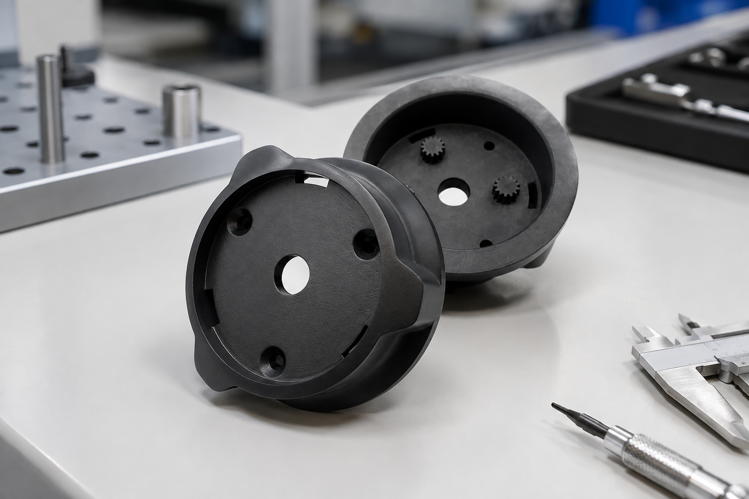
Inspection and Release Evidence
Review the controlled drawing and acceptance method for the submitted plastic part before making a quality claim. The RFQ should identify datums, critical dimensions, surface locations, sampling, material identity and required records. Send the drawing, requested report and acceptance method so the written quotation can define the inspection scope.
Zhenling Manufacturing Base
Zhenling was founded in 2006. Operations are based at an 8,000 m² plant in Jiashan County, and the site includes a 6,000 m² workshop.
For dimensional inspection, the quotation must identify the proposed equipment category, feature coverage, usable range, calibration status, uncertainty and report scope. Equipment names alone do not establish optical, stress or end-use acceptance.
Drawing-to-Release Workflow
To initiate polycarbonate machining, provide STEP, IGES, and 2D dimensioned drawings with quantity and revision status. Our engineer-driven review establishes assessability before Decisions are made on particular polycarbonate grades or acceptability methodology, resulting in a written quotation detailing price, timeline, documentation, and technical points.
01
Controlled Files Sent. STEP or IGES geometry and 2D dimensioned drawing.
02
Avoidance of Doubt. We review intended application before material or accepting grades decisions.
03
Assessability Checks. Before deciding on any technique, engineer looks for potential challenges.
04
Quotation Released. Details price, delivery timeline, required documentation and technical points.
05
Sequence Optimization. Routing per the drawing for rough/finish passes and protected faces.
06
Release & Record Closure. Send over documentation package and logistical data after ship.
Design Notes that Reduce Recutting
| Feature | Buyer benefit | Review focus |
|---|---|---|
| ThinBroad Wall | Flatness State ambiguity lessness about measurement state | Support face clamp load, stock allowance, and post-release inspection burden. |
| Deep Pocket | Fewer avoidable tool marks and less trapped heat | Tool access chip exit corner radius and finishing pass burden review. |
| Thread Insert | Fewer Avoidable Tool Marks and Clearer Assembly Acceptance | Engagement, edge distance, assembly load and crack-sensitive transition burden. |
| Clear Face | finish is priced and inspected against the right question burden | Functional Cosmetic or optical classification data burden. |


Process and Material Trade-Offs
Polycarbonate machining can be a practical route when stock geometry, drawing revisions and tooling flexibility matter. Material or process selection can shift risk into appearance, assembly or validation, so any application-specific standard must be named and reviewed for the order. Tighter tolerance alone does not define the full risk, guarantee the clearest appearance or make CNC the lowest-cost route.
PROJECT CONDITION
BUYER TOOLS
Polycarbonate CNC Machining Engineering Tools
Yes. CNC polycarbonate machining avoids melted edges when the actual setup controls heat and removes chips before they’re recut. A sharp cutting tool, suitable cutter geometry, stable fixturing, spindle speed, feed rate, depth, and coolant or air strategy work as a system.
Thin, broad, or long geometry can require more support, more setup work, controlled finishing passes, and inspection after fixture release. The price also reflects blank size, removed volume, critical tolerance, appearance zones, polishing, coating, quantity, reports, and lead time. Send the complete file set so these drivers are priced once.
No. A smooth surface can look clear while residual stress or birefringence remains a separate optical condition. Define transmission, haze, image quality, viewing zone, and the optical measurement that controls acceptance. We don’t substitute ordinary dimensional inspection or visual approval for that test.
No. ASTM D6098-25 covers mechanical-grade polycarbonate shapes and excludes glazing and signage. For a glazing, optical, medical, flame-rated, aerospace, or other regulated application, name the applicable grade and qualification on the drawing and keep the final end-use approval with the responsible validation owner.
Polycarbonate and acrylic are common engineering plastics, but material selection should follow the specified failure mode, appearance, environment, impact resistance, stiffness, chemical exposure, and finishing options. Don’t select PC only because it’s described as high impact, or acrylic only because it’s associated with optical clarity; test the exact grade and geometry.
Send STEP or IGES, a dimensioned 2D drawing, exact PC grade, quantity, critical dimensions, datum scheme, surface zones, inspection requirement, target date and delivery destination. After the inputs are reviewed, the written quotation confirms response timing.
Prototype schedule, drawing-approval start point, finishing, transit, quantity minimum and single-part acceptance are confirmed for the actual revision in the written quotation.
Yes. Dimensional inspection reports and material certificates are available with the shipment on request. State the required report, sampling, material identity, and any special test during quotation so the release package matches your receiving and approval process.
It can, depending on the exact grade, chemical, concentration, stress state, geometry, temperature, and exposure time. Polycarbonate stress cracking can appear after the machining event, so name cleaners, adhesives, hydrocarbon exposure, coatings, and service chemicals before the material and edge condition are approved.
Evaluate injection molding when the design is frozen, recurring demand is stable, and the geometry benefit from molded features or tooling economics. Keep CNC milling or turning in the review when you need a prototype, changing revisions, stock-shape mechanical properties, or a reversible commitment. There’s no honest universal breakeven quantity.
![Shop-Floor Carbon Steel CNC Machining Guide [2026]](https://zhenlingmetal.com/wp-content/uploads/2026/08/carbon-steel-cnc-machining-handbook-r2-featured-150x150.png)