Get in touch with Zhenling Company

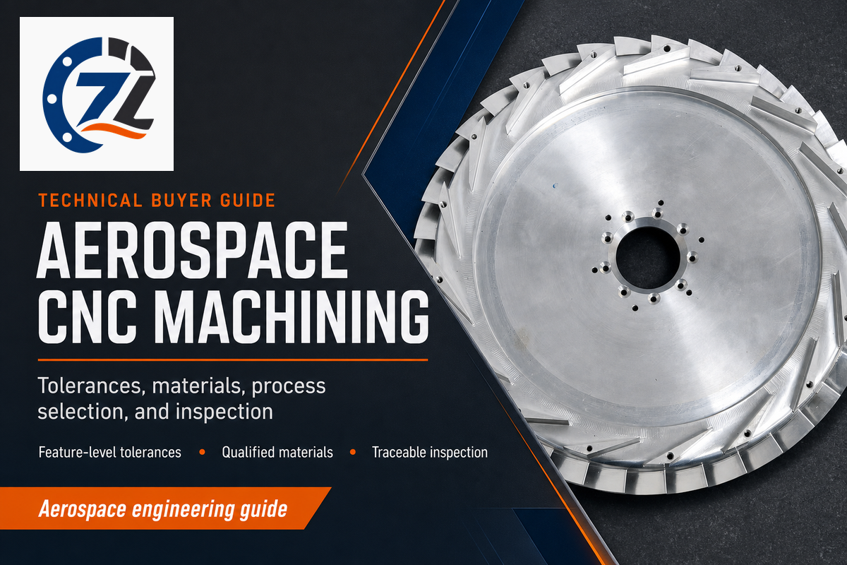
Aerospace CNC machining uses computer-controlled subtractive manufacturing—turning, milling, and multi-axis machining—to produce components that must meet aerospace, space, and defense requirements for certification, material traceability, and tolerance. This cutting process is not fundamentally different from conventional CNC machining; the distinction lies in the standards and process controls applied to it. Aerospace CNC machining is not simply about tighter tolerances. It requires deciding where those tolerances matter feature by feature, which materials and surface finishes suit the application, when 5-axis single-setup machining is cost-effective, what AS9100 adds beyond ISO 9001, and how CNC compares with alternatives such as 3D printing and investment casting.
Revised August 2026.
Across the aerospace sector, aerospace companies increasingly expect suppliers to document not only that a part meets print but also how it was produced. That traceability is one reason the aerospace industry relies on CNC machining for structural hardware. Manufacturers use CNC machining when they need a validated toolpath before the first cut, making the same controlled sequence repeatable across a batch. CNC machines can be pre-programmed with that approved path before production begins.
Quick Specs
| Standard CNC tolerance | ±0.005 in (0.127 mm) |
| Aerospace-critical dimension tolerance | ±0.001 in (0.025 mm) |
| Confirmed aerospace material scope | Aluminum (6061, 7075, 5052, 2024); stainless steel (303, 304, 304L, 316, 316L, 321); carbon & alloy steel (Q235A, Q345D, 45#, 42CrMo-class) |
| Current governing certification | AS9100D (Rev D, 2016; based on ISO 9001:2015) |
| Multi-axis capability | Imported 5-axis machining centers for single-setup complex geometry |
| Inspection equipment | Hexagon and Leitz CMM systems |
What Is Aerospace CNC Machining? (And How It Differs from Standard CNC Work)
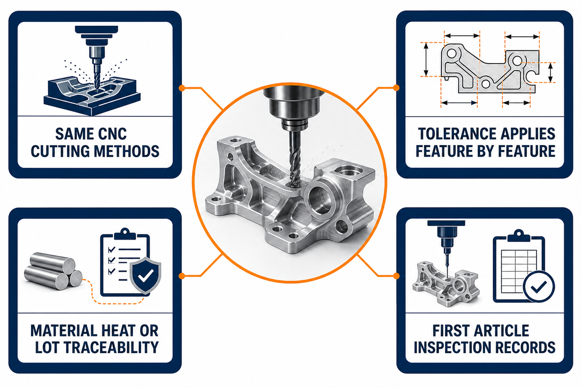
Beyond the paperwork and process controls surrounding the same cutting activity, aerospace CNC machining does not generally use different cutting methods from ordinary commercial CNC machining. A 5-axis machine cutting aluminum stock does not know whether the workpiece is headed to a consumer bracket or an airframe.
What changes is how strictly tolerance applies feature by feature, how much material history follows the part through processing, and what records the customer requires before acceptance. “Aerospace machining” is therefore less a distinct machining technology than a quality and recordkeeping overlay on conventional CNC turning and milling.
| Dimension | Standard commercial CNC | Aerospace CNC |
|---|---|---|
| Tolerance approach | Uniform tolerance band applied to most features | Tolerance assigned by feature criticality — general features stay at standard tolerance, flight-critical features get a materially tighter callout |
| Traceability | Basic order records; batch-level material certs often optional | Material heat/lot traceability tied to the part; first article inspection (FAI) records on new part numbers |
| Material certification | Mill certs sometimes summarized or skipped | Full certificate of conformance expected, tied to the specific heat or batch used on that part |
What is the difference between aerospace machining and standard CNC machining?
Procedurally, the distinction is not mechanical: the same 3-axis or 5-axis CNC mill can produce either workpiece. Aerospace production adds feature-level tolerance setting and the related paper trail, including material certificates, first article inspection documents, and, in some cases, AS9100 quality-system evidence.
What is CNC Machining and why is it important for the Aerospace Industry?
CNC machining is used to produce parts for aerospace by removing material from bar stock or a solid billet along computer numerical control toolpaths generated from a CAD/CAM model. Applications of CNC machining range from structural brackets and housings to fasteners and fittings; advanced CNC equipment can carry the same CNC manufacturing plan from prototypes into production batches.
Much of the versatility of CNC machining comes from CNC machining’s ability to work with aluminum alloys, alloy steels, and stainless steels under one core process. CNC machining is commonly used for this structural work because it avoids dedicated casting tooling, so it is commonly used in the aerospace supply chain when designs may change. For turned parts, CNC turning controls roundness and concentricity, while CNC milling produces flat faces, pockets, and multi-plane features. CNC machining is also suited to parts that combine those feature types in one process plan.
Programs rely on CNC machining because CNC machining ensures that the process and inspection plan applied to the first accepted unit can be repeated across the batch. In aerospace production, machining is employed to produce repeatable components when that traceability matters. CNC machining plays a defining role in machining in the aerospace industry for ordinary structural hardware as well as tight-tolerance parts. An advanced aerospace program can use the same machine controls and documented inspection method across both categories, which is part of what CNC machining provides beyond shape-making alone.
Materials Used in Aerospace CNC Machining: Qualified Families and Limits
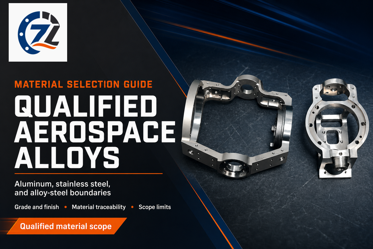
Materials in aerospace CNC machining are selected by qualified family and program-specific grade and finish; the three families below cover most structural, fluid-system, and fastener work. Across those families, materials used in aerospace CNC programs and across aircraft and aerospace production, along with materials for aerospace production more broadly, balance strength, corrosion resistance, machinability, and traceability. Components for the aerospace supply chain, whether components for the aerospace field or components for the aerospace industry, commonly draw from these families. Each can be used in aerospace CNC machining and is well suited for aerospace structural or fluid-system work when its grade and finish match the specification.
A 2025 peer-reviewed CNC metrology study across five materials found that measurement variability changes with the material and instrument, reinforcing the need to bind a qualified grade to its inspection plan.
Before looking at specific alloys, it helps to understand that aerospace CNC machining services tend to work with a smaller set of materials than general precision CNC machining services. This limitation is not about machine capability; aerospace programs usually define a narrower range of certified, traceable materials for each part family.
These strength and weight numbers explain much of the alloy-selection logic that follows. 6061-T6 aluminum has a tensile strength around 45,000 psi (310 MPa) at a density of about 0.098 lb/in³ (2.70 g/cm³), while 7075-T6 reaches roughly 83,000 psi (572 MPa) at a nearly identical density. That strength gap is a large part of why 7075 appears more often in load-bearing brackets and 6061 in general structural and housing parts. 304 stainless steel has a tensile strength around 85,000 psi (585 MPa) and markedly better corrosion resistance than either aluminum grade, but at roughly three times the density (about 0.29 lb/in³ / 8.0 g/cm³). That is the strength-to-weight-versus-corrosion trade a designer makes when choosing between the two families for a given part. Machinability follows the same pattern: carbide tooling commonly runs 6061 aluminum at cutting speeds around 800–1,200 surface feet per minute, while tougher, more work-hardening-prone 304 stainless is commonly cut at only 100–150 surface feet per minute. This difference is part of why a stainless part usually has a longer cycle time than an aluminum part of similar geometry.
| Material family | Common grades | Typical aerospace role |
|---|---|---|
| Aluminum | 6061, 7075, 5052, 2024 | Brackets, housings, avionics mounts, structural fittings — our team runs these on 3/4-axis high-speed milling |
| Stainless steel | 303, 304, 304L, 316, 316L, 321 | Fluid-system fittings, valve bodies, fasteners, corrosion-exposed structural parts |
| Carbon & alloy steel | Q235A, Q345D, 45#, 42CrMo-class | Load-bearing structural brackets, pressure-adjacent hardware |
| Titanium & nickel superalloys (Inconel-type) | Industry background only — not covered as a Zhenling aerospace capability in this guide | Hot-section / engine components industry-wide |
⚠️ Important
Titanium, Inconel, and other nickel superalloys are widely used in aerospace hot-section and engine parts, but those materials fall outside this guide’s capability scope. They appear here only to describe industry practice, not as services we offer.
Surface treatment: passivation and anodizing
Machining, welding, forming, or heat-treating can disrupt the microscopically thin chromium-oxide layer that protects stainless steel. Aerospace components made from these alloys therefore often need passivation after fabrication. AMS 2700 (aerospace standard) and ASTM A967 (general steel standard) define process parameters, test methods, and batch acceptance requirements. Aluminum parts may instead need anodizing or a coating for their service environment; ProtoLabs’ “Surface finishes” comparison summarizes common plating, coating, and anodizing options. Drawings should specify the treatment that matches the material and operating conditions.
Is titanium always required for aerospace CNC parts?
No. Most structural components, fittings, and housings use the aluminum, stainless steel, and carbon/alloy steels discussed above because those materials balance strength, corrosion resistance, machinability, cost, and lead time. Designers turn to titanium and nickel-based superalloys mainly when hot sections or engine components require high-temperature strength, so neither material family is the default for an airframe or general assembly.
Aerospace Machining Tolerances: Why Not Every Feature Needs ±0.001 in
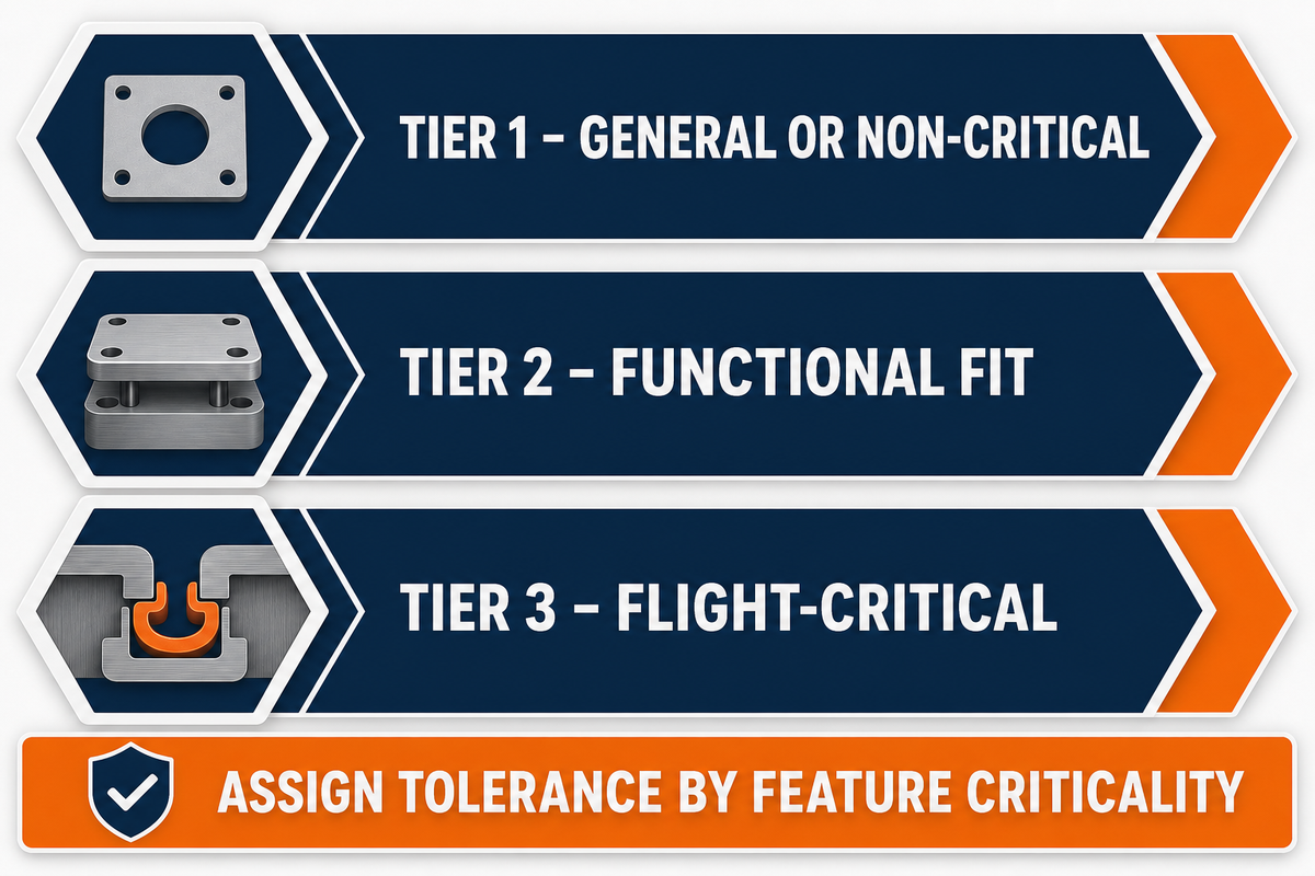
Setting every tolerance on a drawing to the tightest value machining can achieve may sound safe, but it carries a considerable cost. According to a 2008 Sandia National Laboratories machining study, machining tolerance costs rise steeply rather than linearly, so a few unnecessarily tight tolerances can add significant cost to an airframe component. Instead, most engineers take a feature-based approach: they rank each feature by criticality and assign a tolerance based on the part’s function.
±0.005 in (0.127 mm)standard CNC tolerance
±0.001 in (0.025 mm)flight-critical dimension tolerance
The 3-Tier Aerospace Tolerance Model
One reasonable approach to prioritize features on your drawing is by what would happen if a dimension were to deviate:
| Tier | Typical feature | Typical tolerance |
|---|---|---|
| Tier 1 — general / non-critical | Clearance holes, cosmetic edges, non-mating faces | Standard shop tolerance, around ±0.005 in |
| Tier 1 — general / non-critical | Fastener clearance holes, #10 to 3/8 in hardware | ±0.005–0.015 in on hole diameter, depending on fastener class |
| Tier 1 — general / non-critical | Non-mating outer profile and pocket walls | ±0.010 in general profile tolerance |
| Tier 2 — functional fit | Bearing bores, register diameters, mating datums | Commonly ±0.005–0.010 in on typical aerospace hardware |
| Tier 2 — functional fit | Pin and dowel locating holes | ±0.0005–0.001 in diametral tolerance for a slip or press fit |
| Tier 2 — functional fit | Threaded fastener pilot holes | ±0.002–0.004 in on thread pitch diameter callouts |
| Tier 3 — flight-critical | Sealing/mating faces, load-path interfaces | Down to ±0.001 in (0.025 mm) on the specific dimensions that drive fit or load transfer |
| Tier 3 — flight-critical | Bearing bore diameters on rotating assemblies | ±0.0002–0.0005 in on roundness and diametral tolerance |
| Tier 3 — flight-critical | Flatness on gasket and seal mating faces | 0.0005 in flatness over a 4 in span, verified by CMM |
Worked Example: Classifying a Structural Bracket
Consider an aluminum mounting bracket with a fastener clearance hole and a machined face that rests against an actuator housing. The hole only needs enough clearance for the bolt, so it remains a Tier 1 feature at the default ±0.005-in shop tolerance; tightening it would not improve the bracket’s function. By contrast, the mating face determines how squarely the bracket sits against the actuator and how much clamping force the bolt applies when torqued. If that face is uneven or misplaced, the actuator may jam or the connection may lose clamping force. The face is therefore classified as Tier 3 and receives a specific ±0.001-in callout instead of a blanket instruction. The same bracket uses two tolerance tiers on different features, which is precisely what feature-level tolerancing means.
This reflects standard engineering practice rather than a new concept. Sandia’s cited study used a “circle-diamond-square” design from the National Aerospace Standards document NAS-979, “Uniform Cutting Tests”, first issued in 1969, to evaluate machine-accuracy capabilities against expected tolerances in aerospace applications. Engineers commonly specify tolerance callouts with geometric dimensioning and tolerancing (GD&T) under the American Society of Mechanical Engineers’ ASME Y14.5 standard, which Protolabs’ reference guide to CNC tolerancing explains in practical terms. A working tolerance range of 0.005-0.010 in for common features is widely reported. Some job shops report extremely tight tolerances around 0.001 in, or 0.025 mm, but buyers should treat that figure as a shop-specific benchmark rather than a universal industry standard.
Narrowing a tolerance callout from about 0.2 mm to 0.02 mm — an order of magnitude — changes the necessary tooling, scheduling, and inspection approach for that individual feature, not just the number on the drawing.
Aerospace components often carry callouts from more than one tier, so engineers assign tolerance by feature instead of applying a flat value. Achievable dimensions at each operation depend on tool rigidity, stock material, and setup count. A precision machined Tier 3 mating face can sit beside a Tier 1 clearance hole on the same bracket and legitimately use a different callout. That feature-level reasoning shows what aerospace CNC machining requires and distinguishes CNC machining aerospace parts from generic CNC work.
Thermal expansion is part of why some flight-critical dimensions are held and verified under controlled conditions rather than measured straight off the machine. 6061 aluminum has a coefficient of thermal expansion around 13.1 µin/in/°F (23.6 µm/m/°C), while 304 stainless expands more slowly at roughly 9.6 µin/in/°F (17.3 µm/m/°C) — on a 10 in aluminum part, a 20°F swing between a warm shop floor and a climate-controlled inspection room can shift a measured dimension by roughly 0.0026 in, which is one reason precision inspection rooms are commonly held near a stable 68°F (20°C) reference temperature.
What is precision aerospace machining?
Precision aerospace machining is CNC turning or milling applied to the tighter end of the tolerance tiers above, especially functional-fit and flight-critical features, with enough traceability to demonstrate that the part met the specified tolerance rather than merely being cut on capable equipment.
How are tight tolerances verified on aerospace parts?
Flight-critical and functional-fit features are often checked with a CMM rather than handheld tools because CMM results can be documented and traced directly to the drawing’s GD&T callouts. Less-critical general features can often be checked with simpler tools such as calipers. The inspection plan—what is CMM-checked versus hand-checked—is discussed later in this guide.
5-Axis CNC Machines for Aerospace: Fixturing and Single-Setup Strategy
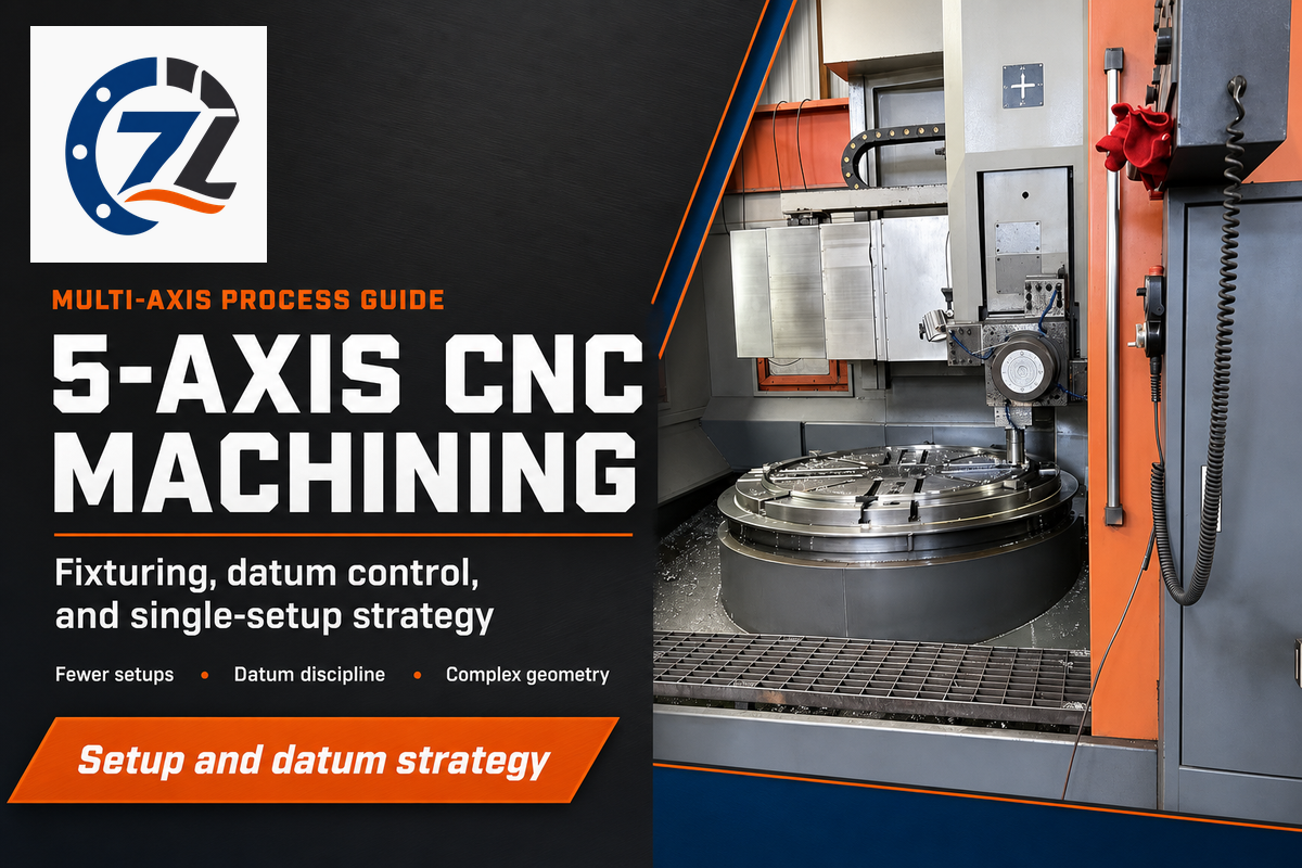
Each time an operator removes a part and reclamps it in a fixture, the new setup can introduce a registration or indexing error. In a chain of dimensions, these small errors add to the overall tolerance stack. Single-setup 5-axis milling reduces the number of independent setup errors on difficult aerospace shapes; fewer setups mean fewer sources of error.
Worked Example: Tolerance Stack-Up Across Three Chained Dimensions
Suppose a bracket has three chained dimensions in series, each individually toleranced at ±0.05 mm, ±0.03 mm, and ±0.02 mm. Adding those tolerances directly (the conservative “worst-case” method) gives a total possible stack-up of ±0.10 mm, the number a designer would need to budget for if everything happened to land at its worst-case value simultaneously. Using the statistical root-sum-square (RSS) method instead — √(0.05² + 0.03² + 0.02²) — gives roughly ±0.062 mm, which better reflects the more realistic case where the individual errors are not all extreme in the same direction at once. That gap between those two numbers, about 0.038 mm, is exactly the kind of margin that determines whether a tight-fitting assembly passes or requires rework, and every additional machine setup in the process is a fresh opportunity to add another error term to that same stack.
A general illustration of tolerance stackup breakdown from a supplier engineering perspective lists seven common sources: errors in datum selection, workpiece shift during machining, fixture-induced deformation, thermal expansion, tool wear, multiple setup steps, and use of inconsistent inspection datums, each one with its own mitigation strategies. That same source draws an easy-to-mistake distinction between different types of datums: the datum established by the drawing engineer, the datum established on the part by the shop, the datum established on the CMM by the inspection technician, and the functional datum required for the aircraft assembly. As the source points out, “the largest or easiest surface is not automatically the most reliable datum feature”, which is a point worth remembering before fixture design begins.
Thin-wall fixturing: work-holding strategy for aerospace geometry
Thin-wall aerospace housings and brackets create a specific fixturing problem: clamping force that holds a thick, rigid part steady can deform a thin one. After unclamping, the wall can spring back and reveal an out-of-tolerance feature that measured correctly in the fixture. Industry engineering guidance therefore recommends a “rough, stabilize, recheck, and finish” sequence for thin-wall, asymmetric, or residual-stress-prone parts: remove most of the material, let the part relax, verify its geometry again, and then take the final finishing passes.
Do
- Validate the datum strategy against the design intent before the first cut
- Distribute clamping force across rigid, non-critical features
- Run a trial finishing pass to check for spring-back on thin walls
- Confirm CMM probe access is part of the fixture design, not an afterthought
- Log the setup count per feature on the routing sheet
Do Not
- Over-clamp thin-wall features and assume the deformation reverses cleanly
- Default to the largest surface as the datum without checking it
- Leave locating pins unchecked between production batches
- Ignore fixture thermal growth on long production runs
- Add an extra setup without re-validating probe accessibility
There is a documented technical case for 5-axis single-setup machining on complex, thin-walled channel geometry outside marketing material, too. A Hexagon Manufacturing Intelligence-assigned patent (US8,977,382 B2) on trochoidal channel roughing explains the underlying constraint plainly: a 3-axis machine is limited to translational tool motion along two axes at a time, which can make it physically impossible to rough deep, narrow, thin-walled channels without gouging material that should remain, while the additional rotational freedom of a 5-axis setup, applied through side-cutting (flank) milling along a trochoidal path, makes those same features machinable without that risk. That patent is cited here as evidence that the underlying technique is formally recognized engineering practice, not as a description of Zhenling’s own patent portfolio.
None of this means 5-axis is automatically the right call for every part. Industry sources are consistent on this point: “5-axis machining is not always necessary for every aerospace part—simple plates, spacers, or blocks may be more suited to 3-axis” work, and the more useful question is not “is 5-axis better” but “when do you actually need it.” Trade coverage documents the same tradeoff from the machining side, tying single-setup 5-axis work directly to fewer setups and tighter position-true tolerances on complex aerospace geometry, while noting that fixture and tooling choices such as dovetail work-holding or shrink-fit tool holders still have to match the part, not the axis count.
5-axis machining earns its keep specifically on complex aerospace parts—deep pockets, angled bosses, and multi-plane features that would otherwise need several separate setups. Part of what makes this work is the integration of CNC machining with the fixture and datum strategy discussed above; axis count alone does not determine the outcome. Our aerospace machining capabilities on this front are built around imported 5-axis centers paired with the datum and fixturing discipline covered in this section, not the axis count in isolation. For genuinely complex parts, that combination is what makes single-setup machining worth the investment.
3 Axis vs 4 Axis vs 5 Axis CNC Milling: What Are the Differences?
3-axis machining moves the tool in X, Y, and Z; although this works for flat and moderately stepped geometry, the part must be re-fixtured for features on opposing sides. A 4th axis adds rotation about one axis, allowing features around a cylinder to be cut without re-fixturing.
A 5th axis adds a second rotational component, providing a wider approach range in one setup for sculptured or deeply pocketed geometry, as described in the preceding tolerance-stack discussion.
Why does single-setup machining matter for tight-tolerance parts?
Each re-setup becomes a potential additional source of alignment variation on top of the variation introduced by the process itself. A part machined in one setup therefore has fewer independent error sources in its final tolerance stack than one machined in three or four separate setups, provided the fixture and datum scheme are sound.
AS9100: What the Certification Actually Requires (Buyer Education, Not a Certification Pitch)
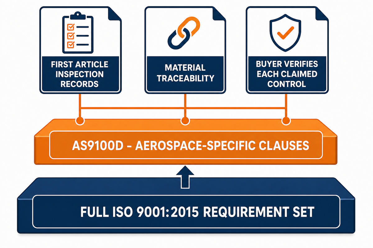
After the single-setup strategy discussed above reduces sources of geometric variation, AS9100 shifts the buyer’s attention to how the shop controls and documents its process. Recent trade coverage of machine shops achieving AS9100 certification shows that buyers still use certification as a supplier-qualification signal. This section explains how to interpret an AS9100 certificate and its supporting documentation; certification services are outside its scope, while our dedicated aerospace capability page covers our machining offering.
| Aspect | ISO 9001 | AS9100 |
|---|---|---|
| Base structure | Generic quality management system requirements | The full ISO 9001:2015 requirement set, with aerospace-specific clauses added on top |
| Traceability & first article records | General record-keeping expectations | Explicit first article inspection (FAI / AS9102-style) records on new or changed part numbers |
| Governing body & current version | ISO | Jointly published by SAE International and IAQG; current version is AS9100D (Rev D, 2016) |
| Regional equivalents | — | EN 9100 (Europe) and JISQ 9100 (Asia-Pacific) carry harmonized requirements |
Buyers should separate well-documented requirements from broader claims. SAE International’s standard page, IAQG governance records, and a NASA Langley Research Center implementation guide describe AS9100 as adding SAE/IAQG “additional aerospace industry requirements” to the ISO 9001 base. First article inspection provides the clearest documented part of a shop’s paper trail. Topics such as configuration management and risk mitigation often fall under aerospace application requirements, but public sources do not present them as one discrete checklist. A buyer should start with FAI records and then ask the supplier to prove each additional control it claims.
What a First Article Inspection Report (FAIR) covers
- ✔ Part number and revision level
- Description and drawing number with revision level.
- ✔ Customer purchase order number
- Preparer signature, date, and customer approval where appropriate.
- Review of materials or processes, and functional testing results.
- Certificate of conformance number and actual measured characteristics.
Selected inspection fields summarized from AS9102 first article inspection guidance. AS9102 defines FAI documentation requirements; it is not itself a supplier certification.
💡 Pro Tip
AS9100 certification is not required on every aerospace purchase order. Whether a contract mandates it depends on the program tier and the specific agreement.
Lockheed Martin’s public supplier quality records provide a clear example of the FAI requirements a leading aerospace OEM can impose on its supply chain. We reference that document only to illustrate what a high-expectation aerospace customer may require, not as evidence that we participate in any program for that OEM.
AS9100D is the current accepted revision of AS9100.
An AS9100D successor, expected to be named IA9100, has been discussed for release in the second half of 2026, likely following an update to ISO 9001. According to the cited transition coverage, some requirements currently framed as informational notes—including training, safety risk, and hazard identification—may become enforceable. Industry guidance also recommends planning for the possibility of two transition audits and reviewing supplier quality agreements for new cybersecurity and export-control requirements before placing purchase orders. Buyers reviewing a supplier’s AS9100 documentation can find details of our certification and traceability capabilities on Zhenling’s Aerospace CNC Machining Services page.
What is the difference between AS9100 and ISO 9001?
AS9100 incorporates the full ISO 9001 framework and adds aerospace-specific requirements, with first article inspection and traceability among the most visible. It is therefore an extension of an existing standard rather than a wholly separate quality-management system for aerospace suppliers in practice.
What does AS9100 certification require beyond ISO 9001?
Most tangibly, AS9100 adds recordkeeping requirements around first article inspection for new or changed part numbers. It also contains other aviation, space, and defense requirements. Buyers should review the supplier’s records for the controls relevant to their program instead of assuming that one uniform checklist beyond FAI applies to every order.
CNC Machining Processes vs. 3D Printing and Investment Casting
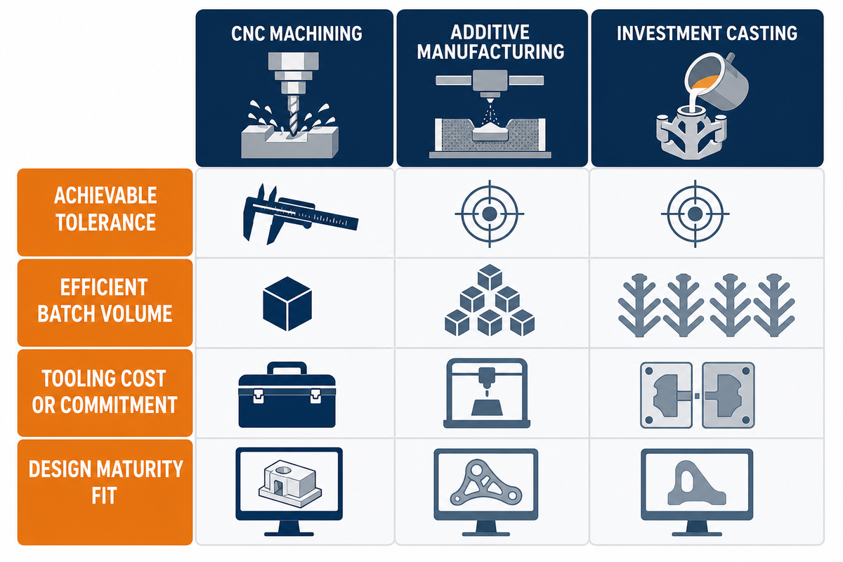
Comparing CNC machining with additive manufacturing processes and investment casting comes down to the same four factors below, whichever CNC machining processes or alternatives are under consideration. Before a design is frozen, programs can use CNC to create functional models of aerospace parts without committing to dedicated hard tooling. Choosing the right manufacturing process in the aerospace supply chain therefore depends on tolerance, volume, tooling cost, and design maturity rather than on a universally “best” method.
This 4-Factor Fit Test makes those constraints explicit. Functional models of aerospace parts can begin in CNC, while a later volume or geometry change may favor additive manufacturing or investment casting. Process selection should follow the project’s current requirements rather than a label.
CNC vs. Casting vs. Additive: The 4-Factor Fit Test
| Factor | CNC machining | Additive manufacturing | Investment casting |
|---|---|---|---|
| Achievable tolerance | Roughly ±0.025–0.125 mm | Roughly ±0.1–0.5 mm depending on process | Roughly ±0.076–0.254 mm as-cast, often machined to finish critical features |
| Efficient batch volume | Strongest fit roughly 10–1,000 units | Strongest fit at very low volume, roughly 1–10 units | Efficient mainly above roughly 100–500 units, once tooling is paid off |
| Tooling cost / commitment | No hard tooling required | No tooling required | Mold tooling commonly runs roughly $2,000–$15,000 |
| Design maturity fit | Tolerant of late design changes — no tooling to redo | Good fit for prototypes and complex internal geometry still in flux | Best reserved for designs that are frozen — tooling investment is hard to walk back |
Worked Example: Running a Bracket Through the 4-Factor Fit Test
Imagine a structural mounting bracket planned for a batch of 150 units, with a flight-critical mating face toleranced at ±0.001 in and a design that engineering has not yet frozen between builds. On tolerance alone, the mating face is tighter than additive manufacturing generally achieves as built, which points toward either CNC machining or investment casting. At 150 units, the volume sits within the efficient CNC range and below the point where investment-casting tooling usually pays off. An unfrozen design also risks stranding the tooling investment if the design changes after the mold is cut. Considering all four factors can therefore favor CNC machining, not because it wins every factor individually, but because no single factor rules it out.
The underlying process-physics factors behind that fit are worth naming explicitly. Typical additive layer thickness is around 20–60 µm, one reason build time for most powder-bed processes scales linearly with part height regardless of print-bed footprint. The minimum wall thickness required for investment casting to fill reliably without defects is typically around 0.060–0.090 in (1.5–2.3 mm), with as-cast surface roughness commonly around 125–250 µin Ra (3.2–6.3 µm).
✔ Advantages
- No tool investment, allowing last-minute changes without the waste of a sunk cost.
- Wide material range within one process family
- Tolerances tight enough for flight-critical mating and sealing features
- Efficient throughout most low-to-medium volume ranges without a tooling threshold.
⚠ Limitations
- Materials are removed as waste (which is costlier for expensive alloys or when producing very large parts).
- Casting becomes the superior alternative for very high volumes once the tooling cost is paid off.
- Very complex (i.e. hollow lattice or channel) internal geometry can be challenging or impossible to remove via a cutting tool.
- The part-per-part process time for complex geometry can exceed that of its equivalent fabricated through additive or casting.
When does CNC machining beat 3D printing for aerospace parts?
CNC machining is often the default when a flight-critical tolerance is tighter than most additive processes can achieve as built, when the specified material is a qualified wrought aerospace alloy rather than a powder-based substitute, or when part quantity makes additive cost and cycle time uncompetitive.
What are the trade-offs between CNC machining and investment casting?
Investment casting can deliver a lower per-unit cost at very high volumes after the tooling has been amortized. However, that tooling investment—often thousands of dollars—is a poor fit for an unfrozen design because a change after the mold is cut requires new tooling. CNC machining avoids dedicated tooling, which makes design changes easier and can remain practical through medium volumes while lower-cost alternatives are evaluated.
Applications of CNC Machining: Aerospace Components and Their Challenges
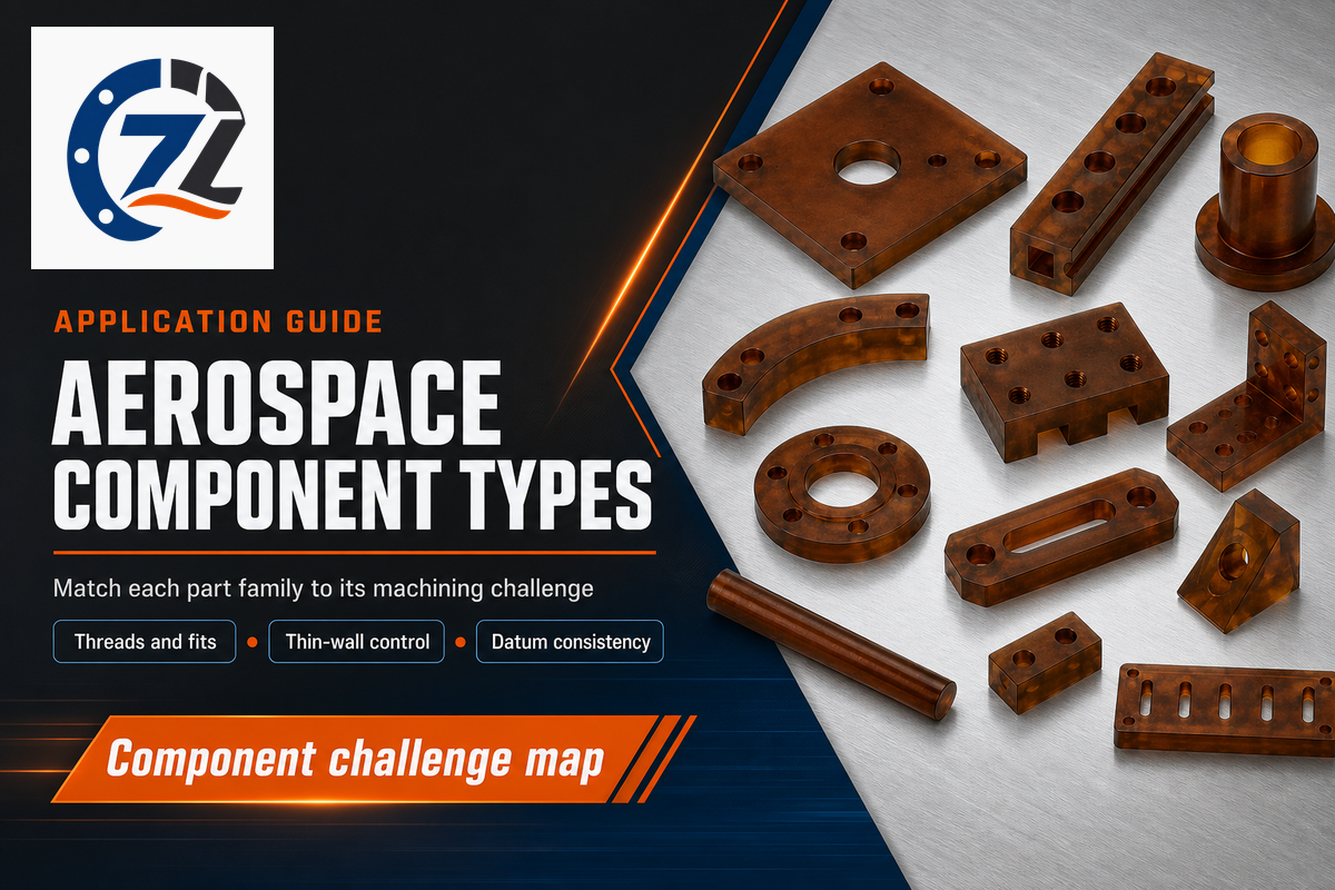
Three factors usually drive the challenges in aerospace CNC machining: tolerance discipline, material traceability, and matching machine and fixture capability to the part. Below, the considerations in aerospace CNC machining are grouped by common component type because similar aerospace parts and assemblies tend to repeat the same challenge pattern. Critical engine parts sit outside this guide’s material and capability scope, so the table separates them from the structural categories.
| Component type | Typical material scope | Primary machining challenge |
|---|---|---|
| Fasteners & threaded hardware | Stainless steel, alloy steel | Thread precision and a corrosion-resistant finish that holds up under repeated torque cycles |
| Bearing-related / rotating-fit components | Stainless steel, alloy steel | Tight roundness and concentricity control on rotating fits |
| Structural brackets & mounts | Aluminum, stainless, alloy steel | Thin-wall distortion control across multiple machined features |
| Structural joints & fittings | Aluminum, stainless, alloy steel | Datum consistency across mating faces so parts fit up correctly on assembly |
| Engine-adjacent (hot-section) components | Outside this guide’s material scope | Requires nickel superalloys and dedicated hot-section certification — a specialized niche this article does not cover |
This is deliberately a short list of the part types most commonly used in aerospace assemblies rather than a full parts catalog. The point is orientation: knowing roughly which challenge category a part falls into before it reaches a machinist’s desk, not building an exhaustive taxonomy of every aerospace-machined component.
Quality Control for Aerospace CNC Machining Services: How Parts Get Checked

Our team runs dimensional inspection on Hexagon and Leitz CMM equipment to verify the flight-critical and functional-fit features discussed earlier in this guide. That step carries the component challenges from the preceding section into a measurable acceptance plan: coordinate measuring machines produce documented, repeatable measurements against the part’s GD&T callouts, which a caliper alone cannot replicate on a complex, multi-datum feature.
Quality control in the aerospace supply chain leans heavily on this kind of documented, traceable measurement rather than a bare pass/fail call. The CNC-machined feature, in other words, is not merely cut to print; it is also verified against the drawing’s GD&T callouts before shipment. The inspection records above are meant to prove that verification.
📐 Engineering Note
Published calibration data for a representative industrial CMM (a Zeiss Prismo 7, referenced in the Sandia machining-accuracy study cited earlier) puts single-axis measurement uncertainty at roughly ±(2.2 + L/300) micrometers and three-axis uncertainty at roughly ±(2.7 + L/250) micrometers, where L is the measured length in millimeters. This is why rigorous inspection reports quote a measurement’s traceable uncertainty band alongside the result, rather than a bare pass/fail number.
Not every feature needs the same measurement rigor. A 2025 peer-reviewed study comparing CNC-turned part measurement across five materials, published in the journal Materials and available via PubMed Central, found that CMM measurement was necessary for high-precision, safety-relevant features, while simpler tools like digital calipers were adequate for non-critical ones. That study’s proposed “hybrid metrology” approach, matching measurement rigor to feature criticality rather than applying one inspection method across the whole part, is a useful analogy for how inspection effort should scale, though it is worth being precise that the study examined measurement method selection specifically, not design-tolerance classification itself.
In practice, shops send Tier 3 flight-critical features from the tolerance model earlier in this guide to full CMM verification and document the results in a first article inspection report. Inspectors can check Tier 1 general features with faster, simpler methods that match the lower consequence of drift.
Surface finish callouts follow a similar tiering logic to tolerance. A general machined surface commonly runs 125–250 µin Ra (3.2–6.3 µm) straight off the mill, a functional mating face is more often called out at 63–125 µin Ra (1.6–3.2 µm), and a sealing or bearing surface can require 16–32 µin Ra (0.4–0.8 µm) — a finish that sometimes needs grinding or polishing to reach, not milling alone. On the flatness side, the 0.0005 in (0.0127 mm) callout over a 4 in (101.6 mm) span mentioned earlier in this guide is a representative example of how tight a Tier 3 geometric tolerance can get.
Trends in Aerospace CNC Machining: Why Its Share Keeps Growing
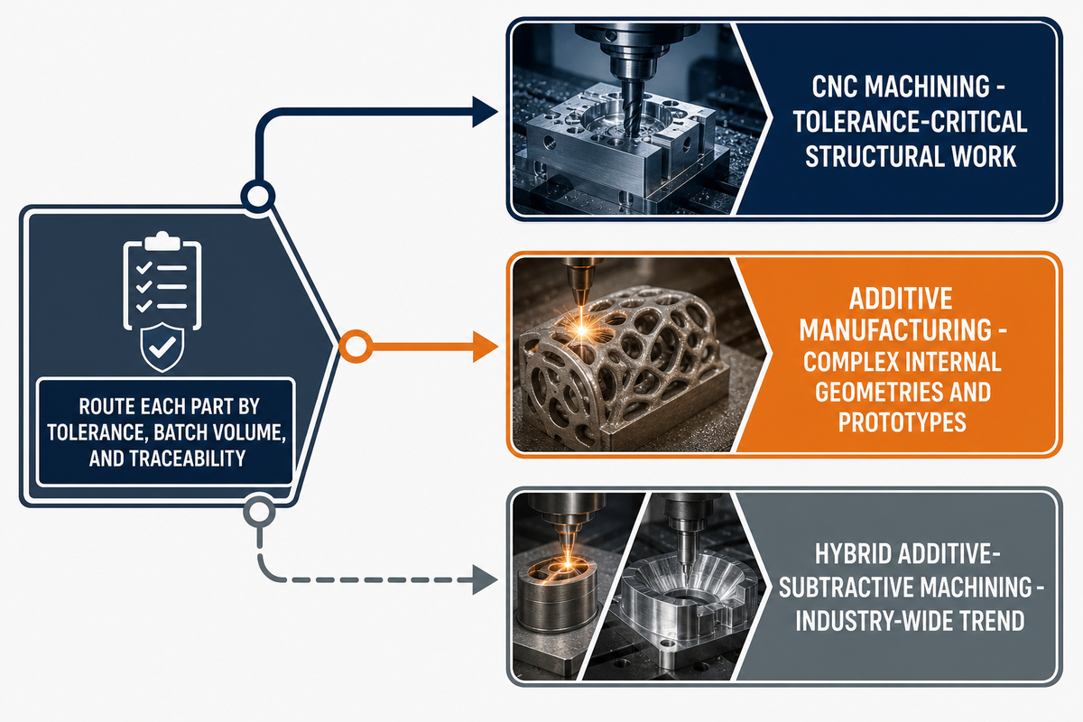
Aerospace manufacturers are not simply choosing between CNC machining and newer processes such as additive manufacturing; they are routing each part to the process that meets its tolerance, batch-volume, and traceability requirements. CNC machining continues to win much of that routing in flight-critical structural work.
Industry survey data from the last few years supports that conclusion better than just a simple “additive manufacturing is replacing CNC” narrative: a joint survey by the Royal Aeronautical Society and Protolabs found that acceptance of CNC machining among aerospace manufacturers was 53.85% in 2023, 51.41% in 2024, and then 54.32% in 2025 – a net increase over the three years, not a steady, uninterrupted increase. Another industry survey by Grand View Research puts CNC machining at 78.9% of precision-machining market revenue, and projects aerospace & defense as the fastest-growing end-use segment, driven by demand for lightweight, high-tolerance, complex structural parts such as turbine blades and landing gear.
54.32%CNC adoption among aerospace manufacturers, 2025
78.9%CNC share of precision-machining market revenue
That kind of growth is not occurring because additive manufacturing is stagnating. One market research forecast puts aerospace-specific additive manufacturing at a 14.33% compound annual growth rate through 2034—a high-growth segment in its own right. The more accurate explanation for aerospace’s growth in precision machining is scenario segmentation: additive manufacturing is making breakthroughs in complex internal geometries and prototypes where it has a real advantage, but CNC machining maintains its lead in tolerance-critical and traceability-intensive structural parts, where certification maturity and dimensional consistency outweigh shape freedom.
Other market signals reinforce this segmentation. Industry market research identifies 5-axis CNC machine tools as the fastest-growing configuration, with an estimated 8.25% compound annual growth rate through 2031, because parts such as turbine blades, orthopedic implant stems, and aerospace brackets benefit from fewer secondary setups. That research connects defense budgets, re-equipment programs, and acquisitions with investment in high-complexity CNC capacity. It also points to AI-generated toolpaths and hybrid additive-subtractive machining centers that may unlock new possibilities in aerospace part design and new possibilities in aerospace manufacturing; these are industry-wide trends, not capabilities we claim for our aluminum, stainless steel, and carbon-steel aerospace work.
Overall, the trends in aerospace CNC machining favor scenario segmentation over wholesale process replacement, a useful indicator for the future of aerospace manufacturing. CNC machining is often the default for the structural work examined here. CNC machining has become a process buyers expect to document with evidence that a part meets print; the 2025 peer-reviewed metrology study illustrates why high-precision features need traceable CMM results rather than a bare measurement claim.
Key takeaway
CNC machining is not losing ground in aerospace — RAeS and Protolabs’ 2025 survey puts adoption among aerospace manufacturers at 54.32%, and it keeps winning the tolerance-critical, traceability-heavy structural work that additive manufacturing and casting are not built to own.
Our shop in Jiashan, Zhejiang ships about 80% of its production to export customers. To serve those buyers, our standard process includes material certificates, FAI reports, CMM records, and the recordkeeping practices described in this guide. Buyers evaluating a part for an upcoming program can review our materials, certifications, equipment, and machining capabilities on the aerospace capability page linked above.
Frequently Asked Questions
Q: How does CNC machining work for aerospace?
A CAD model is converted into a CAM-generated toolpath, then a computer-controlled machine cuts material away from a solid block or bar to match it.
For aerospace parts specifically, that same subtractive process runs alongside additional controls: tolerance is assigned by feature criticality rather than applied uniformly, the material used is tied to a traceable heat or batch, and the finished part is typically measured on a coordinate measuring machine and documented in a first article inspection report before it ships. That machining itself is standard CNC turning or milling, the layer of process control and paperwork around it is what makes it “aerospace.” That distinction shows up most clearly on flight-critical dimensions, where tolerance can run as tight as ±0.001 in and every inspection result gets logged against the drawing’s GD&T callouts rather than checked once and set aside.
Q: What is CNC Machining and why is it important for the Aerospace Industry?
CNC machining is computer-guided subtractive manufacturing, and it matters to aerospace because it delivers repeatable, documentable precision at production scale, with traceable inspection records for every batch.
To perform reliably from the first unit through the thousandth, aircraft structures need consistent components. CNC machining supports that repeatability with a clear process history and documented compliance with the aerospace requirements that apply to the program. The resulting process and inspection data are repeatable and available in formats that aviation quality teams can review.
Q: Is titanium always required for aerospace CNC parts?
No, most structural, fitting, and housing-type aerospace parts use aluminum, stainless steel, or carbon/alloy steel instead of titanium when their specifications do not demand hot-section alloys.
Titanium and nickel-based superalloys are used primarily in high-temperature engine hot sections where exceptional strength is required. Most mounting hardware, fasteners, housings, fittings, and airframe components instead use the aluminum, stainless steel, and alloy steel families described above. These materials generally cost less and machine more efficiently when the specification does not require a hot-section alloy.
Q: What is the difference between AS9100 and ISO 9001?
AS9100 contains the entire ISO 9001 standard plus additional aerospace-specific requirements, such as material traceability, risk control, and documented first article inspection records for suppliers.
The most tangible addition—and the one a quality inspector will want to review above all—is first article inspection. FAI reports follow SAE AS9102, while the broader AS9100 quality framework builds on ISO 9001:2015.
Q: Can the same CNC shop handle both prototype and production runs for aerospace parts?
Yes, in principle, the main operational difference is fixturing and process planning, not a different machine or material qualification, as the program moves from development into repeat production.
During prototyping, a job can use adaptable general-purpose fixturing to produce the small quantity required. For production runs, a business may invest in dedicated fixturing and a streamlined process plan once the design is stable. If the organization performs both prototype and production machining on one part number, first article inspection must be repeated after the design changes from prototype to production status.
Q: What does “aerospace-grade” actually certify about a machined part?
On its own, “aerospace-grade” is not a formal certification; what matters is the specific material certificate, tolerance callout, and inspection record behind the part.
Although the phrase generally suggests that a part meets demanding aerospace tolerances and traceability requirements, no single formal qualification grants that label. To verify the claim, request the actual evidence—material certificates of compliance, feature tolerances on the drawing, and, where applicable, a first article inspection report—rather than relying on the terminology alone.
Why We Write This
Our engineers use the same feature-by-feature tolerance logic and material-selection approach during internal reviews before an aluminum, stainless steel, or alloy steel job enters the shop. They also distinguish AS9100 requirements from the underlying ISO 9001 framework when reviewing aerospace drawings and their recordkeeping needs.
We wrote this article for buyer education rather than as a sales pitch. Sourcing, cost, and supplier-qualification guidance remains on the separate aerospace CNC machining services page. Reviewed by the Shanghai Zhenling Hardware Co., Ltd. team.
References & Sources
- Quantification of Uncertainty in Machining Operations for On-Machine Acceptance (SAND2008-6396) Sandia National Laboratories
- Dimensional Accuracy and Measurement Variability in CNC-Turned Parts Using Digital Vernier Calipers and Coordinate Measuring Machines Across Five Materials, published in Materials (2025), via PubMed Central
- AS9100D Standard SAE International
- AS9100 / IA9100 Standard Governance IAQG (International Aerospace Quality Group)
- AS9100 Quality Systems NASA Langley Research Center
- AS9100D Explained: What the “D” Means and What Comes Next Smithers
- IA9100 Is Coming: Changes to the AS9100 Standard The Core Solution
- Quality Magazine AS9100/IA9100 transition coverage
- What Is AS9102 First Article Inspection? AS9100 Store
- First Article Inspection for Aerospace Criterion Precision
- RMS Quality First Article Inspection Requirements Lockheed Martin (supplier quality requirements)
- Betts Precision Achieves AS9100 Certification Aerospace Manufacturing and Design
- Fine-Tuning Tolerances for CNC Machined Parts Protolabs
- Plating and Other Finishing Considerations Protolabs
- CNC Machining Tolerances Unitritech
- What Are the Tightest Machining Specs? Cheetah Precision
- Passivation Standards for Aerospace Stainless Steel Valence Surface Technologies
- CNC Machining Tolerance Stack-Up: Formula, RSS, and Practical Example Rapid Efficient
- Fixture Ideas for an Aerospace Part Practical Machinist forum (practitioner discussion)
- r/Machinists community discussion Reddit (practitioner discussion)
- 5-Axis Aerospace Machining: Reducing Setups, Risk and Inspection Problems Tarvin Precision
- 5-Axis CNC Machining: When Do You Actually Need It? RPM Fast
- Aerospace Precision Machining: Meeting Strict Requirements GOSCPM
- Shop Works to Get the Most Out of Its Five-Axis Capabilities Modern Machine Shop
- Applying Automotive Machining Lessons to Aerospace Modern Machine Shop
- US8,977,382 B2, Automatic Method for Milling Complex Channel-Shaped Cavities Google Patents (assigned to Hexagon Manufacturing Intelligence)
- Aerospace Manufacturing in 2025: The Key Issues Royal Aeronautical Society / Protolabs survey
- Precision Machining Market Report Grand View Research
- CNC Machine Tool Market Mordor Intelligence
- Aerospace Additive Manufacturing Market IMARC Group
- Aerospace & Defense Manufacturing Market Coverage Coherent Market Insights
- Manufacturing Process Selection Knowledge Base Hubs (Protolabs Network)
- Casting vs. Machining RivCut