Get in touch with Zhenling Company

Acrylic (PMMA) CNC Machining [Engineer’s Guide]


Updated August 2026
How to Plan Acrylic (PMMA) CNC Machining
Clear acrylic can leave the CNC machine looking acceptable and still fail after polishing, assembly, cleaning, or optical inspection. Acrylic (PMMA) CNC Machining refers to the controlled milling or turning of polymethyl methacrylate stock into a defined part and delivered state. Stock history, heat, chip removal, restraint, finishing, later fluid contact, and the inspection method all affect that state.
Quick answer
Plan Acrylic (PMMA) CNC Machining as a linked set of states, not as a search for one spindle speed. Identify the exact PMMA stock and orientation, create a small trial window for heat and chip behavior, match support to the feature, define the post-finish condition, and inspect the part at an agreed temperature with methods tied to function. When a defect becomes visible, use a cause-and-check sequence before changing any setting.
What does Acrylic (PMMA) CNC Machining actually change?
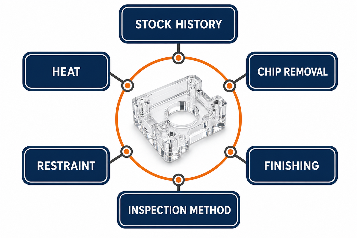
PMMA, commonly known as acrylic or acrylic glass, is a transparent thermoplastic. CNC milling and CNC turning can produce precise geometry without molding tooling, but the cut also changes the material near the new surface. This distinction governs every later evidence decision.
Transparency alone does not establish a grade or compliance state. Labels such as “medical devices” describe an application context, not a verified material grade or compliance result. Material selection must follow the actual function, exposure, and evidence requirement rather than transparency alone.
Clarify search terms before comparing a process
Terminology note: Acrylic CNC machining, CNC acrylic machining, PMMA CNC, acrylic machining, and machining PMMA are search-language variants. In this guide to understanding PMMA machining, they describe subtractive work on acrylic plastic that produces machined acrylic or CNC machined parts. PMMA is also known as acrylic, while acrylic is also used as a loose name for sheets sold under several trade names.
Search language also pairs this topic with surface finish, signage, polycarbonate, impact resistance, chemical resistance, and the phrases “range of applications” and “wide range of applications.” Those phrases are research prompts, not evidence that a selected grade meets a property or compliance requirement. Likewise, cast acrylic and extruded acrylic are supply-form search labels; they do not replace material documentation or a controlled trial. Other query labels—“cnc machining applications,” “acrylic machining services,” “plastic parts,” “signage and display,” “variety of applications,” “plastic machining,” “outdoor applications,” “machine guards,” “UV light,” and “resistant to UV light”—are navigation terms, not evidence of suitability, performance, or compliance.
Readers who want to know about CNC acrylic should separate the verb from the requirement: to cut acrylic or cut PMMA is to remove material, but acrylic cutting does not define the finish on the surface of the acrylic. Custom parts can need dimensional stability, surface hardness, optical data, or control of cracking during machining, so the drawing must name which condition matters.
This guide does not treat an application label as evidence of UV resistance; UV behavior remains a separate material and service requirement.
Likewise, marketing phrases such as “popular choice for CNC machining,” “PMMA offers several advantages,” “several advantages,” or “relatively easy to machine” are not process evidence. Even a tool described as designed specifically for acrylic or a plastic said to be used in CNC machining still needs a trial tied to stock, geometry, chip evacuation, and acceptance.
That changed layer matters. Cutting generates heat and force, exposes fresh polymer, leaves a tool-path texture, and can alter the stress condition around an edge or bore. In the peer-reviewed PMMA study, milling changed the stress at which crazing began under its specific regular and oriented stock conditions. Alcohol exposure shifted the result again. Exact reported thresholds cannot be transferred to another grade or process, but the mechanism is a useful warning: machining and later chemical contact are connected decisions, not isolated events. See the full PMMA crazing study.
This is why “the dimensions were correct at the machine” is only one checkpoint. Yet the real deliverable may also include a stable wall, a polished edge, controlled haze, an adhesive-bonding step, or resistance to a specified cleaning fluid. Each need changes what evidence should be collected.
Start with the PMMA stock state, not the toolpath
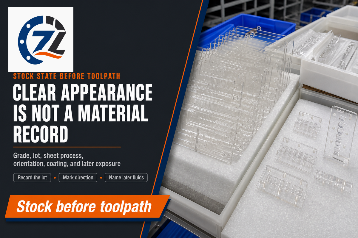
Those downstream acceptance questions make stock identity the next control point. “Acrylic” on a drawing is not a complete material definition. Cast versus extruded is one stock-identity field, not a complete machining verdict. Where applicable, regular and stretch-oriented PMMA introduce another layer: direction may matter. Supply form, orientation, and prior thermal history define the trial’s recorded stock state.
ASTM D4802-16(2024) officially covers monolithic methacrylate sheet for general-purpose applications. It can help identify a sheet document, but it does not prescribe the CNC machining process or establish finished-part optical acceptance.
Minimum stock record for a meaningful trial
- grade, manufacturer, lot, and applicable material document;
- cast or extruded supply form, plus regular or stretch-oriented state where applicable;
- nominal and measured thickness before machining;
- sheet direction marked on the blank when orientation may matter;
- protective film, coating, color, and UV formulation status;
- conditioning, storage, and any prior heat treatment;
- later cleaners, coolants, adhesives, and service fluids.
If a replacement lot arrives, treat it as a state change. Passing one program provides evidence for the recorded stock-process combination, not proof that every acrylic blank will react the same way.
Stock identification also prevents a common communication error: using “clear PMMA” as both a material callout and an appearance requirement. Here, the first describes a polymer family and supplied form; the second may require a visual sample, haze value, transmittance method, or limits on tool marks. Keep those records separate so a purchasing substitution does not silently rewrite a functional requirement.
Control heat through the chip, tool, and path
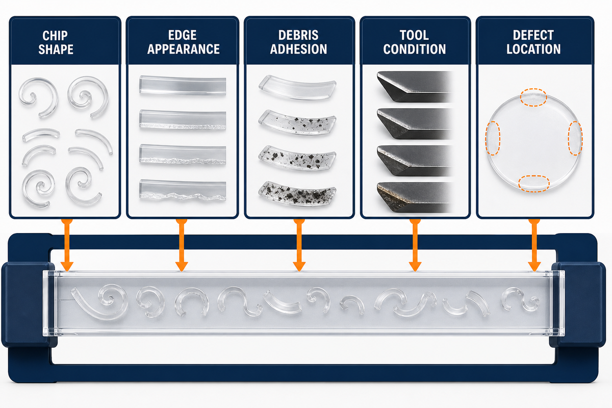
In PMMA machining, a clean chip carries material and heat away. Rubbing leaves more energy near the edge and can show up as smearing, a glossy recut surface, welded debris, or a changing sound. Chipping can point in another direction: brittle edge loading, weak support, an unsuitable entry, tool wear, or a stock-state mismatch.
In one high-speed micromilling experiment, PMMA surface and chip morphology changed strongly with temperature in that test setup. It reported roughly 45 nm near 70 °C and roughly 180 nm near 120 °C under its laboratory conditions. Those roughness values and temperatures are not shop setpoints. What transfers is the coupling: temperature, chip formation, and surface outcome moved together. Read the peer-reviewed experiment for its stated conditions.
Tool geometry, edge condition, engagement, feed per tooth, spindle speed, depth, coolant or air strategy, and evacuation must be considered as a group. Even a sharp cutting tool may stop rubbing without curing chip recutting. More airflow may move chips, yet it does not confirm that a coolant, seal, or adhesive is chemically compatible with the final part.
Observe before changing
Record chip shape, edge appearance, debris adhesion, sound, tool condition, and the location of the defect. Then change one controlled factor inside a bounded trial. Changing five hidden variables may make the next part look better, but it destroys the evidence needed to repeat the result.
Match feature geometry to restraint and cutting direction

Once chip behavior is observed, geometry determines how cutting force reaches the workpiece. Thick plates, thin sheets, and microfluidic walls do not behave as the same workpiece. Feature height, local stiffness, unsupported length, corner radii, clamping position, vacuum coverage, and machining order determine how force reaches the cut. Once surrounding material is removed, a previously stable roughing setup can become unstable.
In 2025, a micro-milling study compared 50 μm (0.05 mm), 100 μm (0.10 mm), and 150 μm (0.15 mm) PMMA walls in microfluidic devices and found that wall deviation depended on both thickness and milling strategy. That study is valuable evidence that strategy and support matter. It is not a universal 0.15 mm minimum wall rule for CNC acrylic parts. Device scale, tools, material, and acceptance method define its boundary. See the full thin-wall study.
Which design details deserve an early trial?
- thin walls that lose support during the final pass;
- deep slots where chips can recut or pack;
- small holes near an edge or bonded interface;
- sharp internal corners that concentrate stress;
- large flat areas affected by vacuum or clamp distortion;
- surfaces whose tool marks lie in an optical path;
- features inspected after polishing, cleaning, or assembly.
Design tips should therefore be tied to function. Increasing a radius changes cutter access and corner geometry, but the drawing still needs to say which edge, surface, or wall is critical and how it will be accepted.
If a 5-axis route has already been selected, use the 5-axis CNC machining guide to separate machine, post, program, and part-proof evidence during validation.
Build a process window without copying universal speeds and feeds
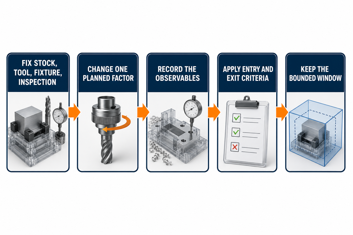
Those feature-specific risks are also why a published spindle speed or feed rate is not a process window. It omits tool diameter, flute count, edge geometry, runout, engagement, stock form, fixturing, machine dynamics, chip removal, and the definition of a pass. Even cutting speeds calculated from diameter and revolutions do not capture how much each tooth removes.
A Northumbria University research record describes a 12-run PMMA milling study that varied 1,000–4,000 rpm spindle speed, 0.2–1.1 mm depth, and 25–100 mm/min feed while measuring roughness, temperature responses, and chip morphology. This public record supports a multi-factor test approach; those ranges remain attached to that paper and machine. They are not a ready-made production recipe.
| Trial layer | Hold constant | Change deliberately | Record |
|---|---|---|---|
| Material | grade, lot, thickness, orientation | none during a parameter comparison | blank identity and conditioning |
| Cut | tool and programmed path | one bounded feed, speed, or engagement factor | chips, sound, edge, debris, cycle step |
| Feature | support and measurement setup | strategy or pass order | form, position, wall deviation, surface |
| Tool | geometry, edge condition, runout | one identified tool factor | tool identity, wear, and observed edge condition |
| Fixture | datum, clamp or vacuum map | one support or release condition | in-fixture and released measurements |
| Evacuation | enclosure and collection setup | one air, coolant, or path condition | chip recutting, packing, and residue |
| Finish | machined allowance and surface identity | one defined finishing step | geometry, texture, appearance, and defects |
| Exposure | cleaner, adhesive, load, time | one approved later-contact condition | crazing, cracking, and functional change |
| After-state | finish, rest time, inspection temperature | only the planned post-process variable | dimension, haze or transmittance if required, defects |
Set entry and exit criteria before the first coupon. Useful windows state what combination was tried, which evidence passed, what failed, and what remains unknown. That record is narrower—and far more transferable—than “these settings worked once.”
Example of a bounded trial decision
Suppose the first coupon shows adhered debris on a deep slot but acceptable outside edges. Record the slot location, chip form, tool condition, engagement, and evacuation route. Keep the stock, tool, fixture, and inspection state fixed; test one planned evacuation or engagement change. This decision is not “faster worked.” It is “under this recorded state, the changed factor removed the slot symptom without breaking the stated edge and dimensional criteria.”
Preserve the PMMA Surface-Failure Timeline before rework
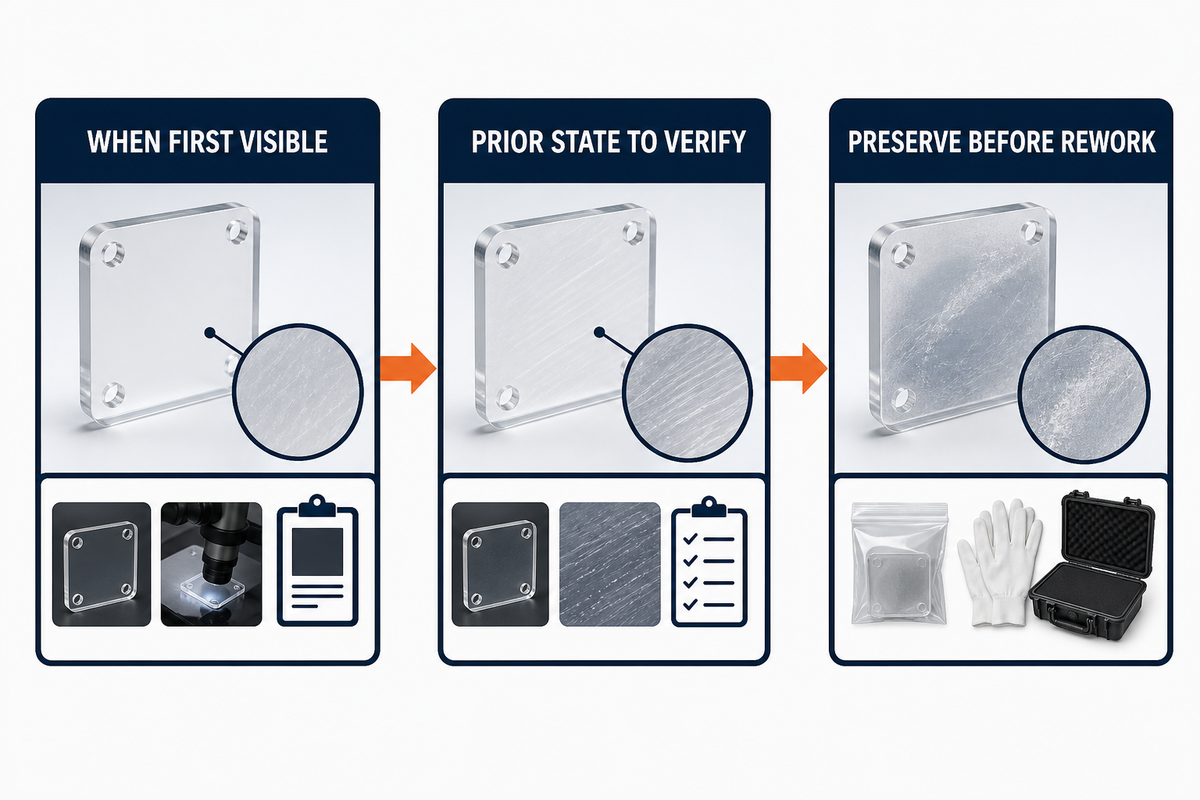
PMMA failures often become visible only after a surface, load, fluid, or inspection state changes. One cloudy edge could reflect cutting heat, chip recutting, finishing residue, cleaning exposure, or the inspection condition. The PMMA Surface-Failure Timeline records when the change first appeared, which earlier state is the candidate to verify, and what physical evidence must be preserved before cleanup or rework.
| Symptom type | Observed transition; plausible causes unproven | Check next / preserve evidence |
|---|---|---|
| Melted or smeared edge | First visible at machine exit; candidate prior state to verify: intact stock or the prior feature | edge macro, chips, tool edge, and contact-zone image before cleaning |
| Chipped corner | First visible at entry or exit; candidate prior state to verify: intact corner before that tool move | fragment, corner position, blank direction, clamp map, and toolpath record |
| Wall bends after release | First visible after unclamping or rest; candidate prior state to verify: in-fixture geometry | paired in-fixture and released data, wall image, rest time, and temperature |
| Crazing after cleaning or bonding | First visible after the named cleaning or bonding exposure; candidate prior state to verify: pre-exposure surface | pre-exposure image, lot, surface, fluid identity, dwell, temperature, and load |
| Clear by eye but fails an optical check | First visible during the optical check; candidate prior state to verify: the declared pre-clean or visual state | cleaning record, instrument method, sampling area, and paired form and surface data |
| Cloudy band near an edge | First visible after cutting, cleaning, or polishing; candidate prior state to verify: the preceding surface image | band location, chip path, residue record, and pre- and post-finish images |
| Hairline cracks after assembly | First visible after fit, torque, or fluid contact; candidate prior state to verify: released part before assembly | torque, fit, hole-edge image, fluid identity, and exposure timeline |
| Hole breakout or burr | First visible at hole exit; candidate prior state to verify: entry face or the prior depth checkpoint | exit-face image, backing, chip path, tool edge, and the prior-depth record |
| Dimension shifts after polishing | First visible after polishing; candidate prior state to verify: the pre-finish measurement | paired measurements, method, finish allowance, rest time, temperature, and setup |
The timeline does not assign a fault verdict. It protects the failed surface and its exposure history from being erased by cleaning, polishing, disassembly, or another CNC pass. Preserve the part, record when and where the change appeared, and compare it with the candidate prior state. Only contemporaneous records can establish whether that earlier state actually passed.
Treat polishing and inspection as new process states
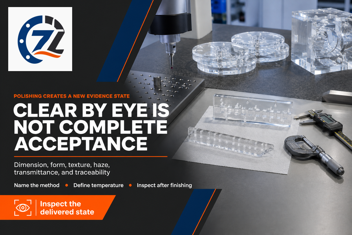
Once a symptom is traced to a process step, the delivered finish still needs its own state. A milled surface, a mechanically polished edge, and a thermally finished edge are different delivered states. Finishing can change geometry, texture, appearance, and the evidence available for acceptance. A finish that produces optical clarity by eye does not automatically prove flatness, profile, haze, light transmission, or freedom from subsurface damage.
The ASME review of ultra-precision cutting treats surface topography, geometrical form, and subsurface damage as separate questions. It also places diamond turning and milling in a specialized process class. That does not promise an optical result from conventional CNC milling; it explains why one roughness number or a photograph can be incomplete evidence.
If the part has an optical requirement, name the property and method. ASTM D1003-21 describes instrument procedures for haze and luminous transmittance of transparent plastics. That method does not choose the project limit. Project drawings, specifications, or approved samples must do that.
What belongs in the inspection state?
- the as-machined, polished, cleaned, coated, or assembled condition;
- the inspection temperature, stabilization time, and restraint state;
- the datum scheme and the features measured after fixture release;
- the instrument, sampling area, direction, and surface cleanliness;
- separate acceptance for dimension, form, texture, and optical properties;
- the agreed rule for visual defects and reference samples.
NIST dimensional metrology guidance explains that temperature, expansion correction, gradients, and uncertainty contribute to a dimensional result. The NIST monograph is general metrology evidence, not a PMMA cutting recipe. Its lesson here is that a dimension without a defined measurement state is hard to compare across locations. The related precision CNC machining guide explains how to read tolerance and inspection records without treating one measurement as complete proof.
For parts with several functions, use an acceptance map. A sealing face may need form and defect checks; a viewing area may need haze or transmittance data; a bonded edge may need a defined cleaning and surface-preparation state. One blanket “polish all surfaces” note can hide those different obligations and make a later failure difficult to trace.
Keep PMMA dust control inside a site-specific safety assessment
Milling, routing, deburring, and polishing can create chips and fine particles in different proportions. The machine enclosure, extraction system, housekeeping method, ignition sources, dust loading, and local rules all affect the workplace risk. An article cannot determine whether a particular installation reaches a hazardous dust concentration or prescribe the control system.
“Any combustible material can burn rapidly when in a finely divided form.”
OSHA includes plastics among materials that can be explosible as dust under the required conditions. Separately, a peer-reviewed Journal of Hazardous Materials study tested PMMA dust clouds exposed to hotspots and electrical sparks. The experiment supports material-specific assessment; its laboratory values are not workplace limits.
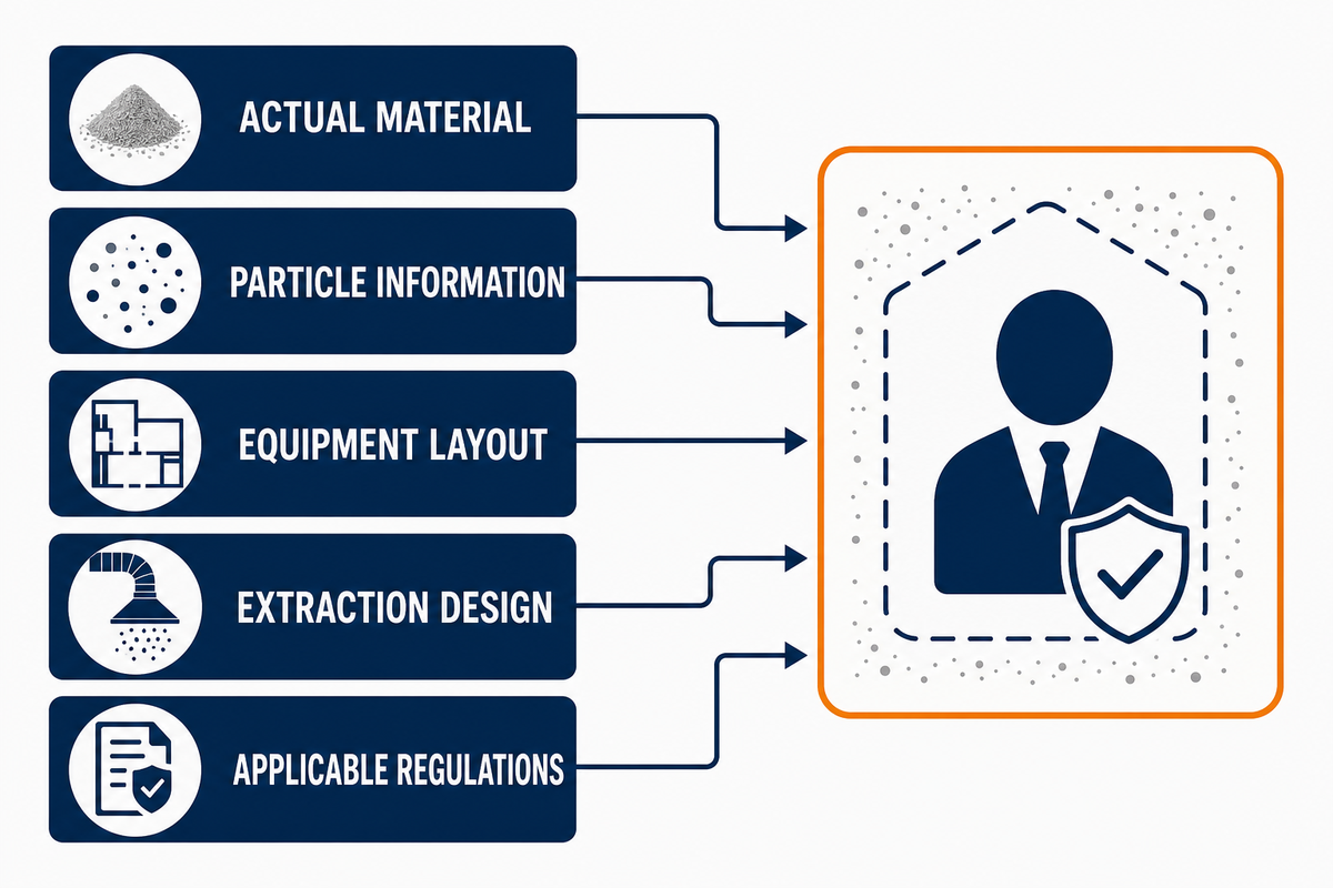
Send the actual material, particle information, equipment layout, extraction design, and applicable regulations to a qualified safety professional. Do not infer safety from the fact that the process mostly produces visible chips.
Build the PMMA Surface-and-Exposure Acceptance Passport
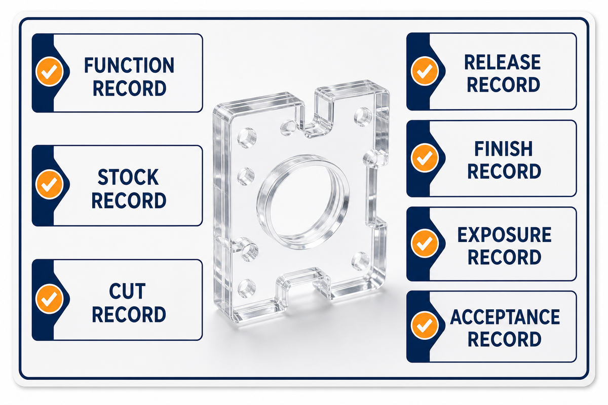
The PMMA Surface-and-Exposure Acceptance Passport is a handoff record for one delivered part condition. It keeps surface history, later fluid contact, released geometry, and the acceptance method together so a clear-looking part is not separated from the evidence that qualifies it.
- Function record: function, critical features, appearance, optical property, later fluids, and acceptance methods.
- Stock record: grade, lot, sheet process, thickness, orientation, coating, conditioning, and blank direction.
- Cut record: tool identity and wear, runout, fixture, path, engagement, speed, feed, chip removal, and observed heat indicators.
- Release record: geometry and surface after the part leaves the fixture and reaches the agreed measurement condition.
- Finish record: polishing, cleaning, coating, bonding preparation, and any geometry or appearance change.
- Exposure record: assembly load, cleaner, adhesive, coolant residue, alcohol, or service fluid with time and temperature.
- Acceptance record: dimensional, form, surface, optical, visual, and traceability records tied to the actual delivered condition.
A late failure should be traced through the passport without erasing earlier evidence. For example, crazing after cleaning may require the exposure record, finish record, machined-surface images, and stock orientation—not just a lower feed rate.
When those records are complete, review PMMA surface state, later exposure, and acceptance methods with Zhenling. That service page owns configuration and quotation intent; this guide remains focused on engineering decisions and verification.
For general education across CNC projects, the CNC machining cost guide explains how setup and inspection affect cost. It does not replace the PMMA service page as the configuration and quotation path.
Key takeaways

Together, the passport records lead to these working rules.
- Define PMMA stock form, lot, orientation, and later chemical exposure before treating any trial as transferable.
- Use chips, edge condition, debris, and feature response as linked heat-and-cutting evidence.
- Bind thin-wall guidance to geometry, support, strategy, and acceptance; don’t turn one research scale into a universal rule.
- Build a controlled trial window instead of copying isolated speeds and feeds.
- Separate visual appearance, dimension, form, surface texture, haze, and transmittance when the function requires them.
- Treat finishing, fixture release, cleaning, and assembly as state changes that can require reinspection.
- Keep dust decisions with the site-specific safety assessment.
Frequently asked questions
The questions below apply those rules to common shop decisions.
Can acrylic be CNC machined without melting?
Yes. A stable cut forms and removes a consistent chip instead of rubbing, while the trial holds stock, tool condition, engagement, evacuation, and inspection state under control.
The workable combination depends on stock, tool, engagement, feed per tooth, spindle speed, runout, path, and evacuation. Start with a traceable blank and a sharp tool, watch the chip and edge, and keep the fixture and inspection state fixed. Confirm the result with a bounded trial rather than transferring a setting from an unknown machine.
What does cast-versus-extruded change in a controlled PMMA trial?
Cast-versus-extruded selection changes the supply-form field that must be held constant and reported; it does not by itself decide machining quality or replace a trial on the actual grade and lot.
Cast versus extruded is one stock-identity field and does not decide machining quality by itself, while stretch-oriented stock adds directionality where applicable. Compare the actual grade, lot, thickness, blank direction, post-finish state, and later fluid exposure. A passed cast-stock trial doesn’t automatically reject extrusion, and a stock label alone doesn’t prove the finished part.
How should a finished PMMA surface be defined and inspected?
The answer must name the delivered process state and the measurement: visual appearance, dimension, form, roughness, haze, transmittance, or an agreed combination after finishing and cleaning.
An as-machined face, polished edge, and ultra-precision-cut surface aren’t interchangeable. State whether acceptance is visual, dimensional, roughness-based, haze-based, transmittance-based, or a combination. Also define the sampling area, cleaning state, inspection temperature, and reference sample where used. Inspect after the specified finishing steps because the earlier machine state may no longer represent the delivered surface.
How should thin PMMA walls be designed for milling?
Design each thin wall with its support, surrounding stock, machining order, cutting direction, release behavior, and inspection method; then trial the representative geometry instead of copying a universal minimum.
Wall height, length, thickness, surrounding stock, cutter engagement, tool path, and fixture-release behavior all matter. Trial the critical geometry at representative scale; don’t apply a microfluidic research dimension as a general shop minimum.
What inspection-state evidence should a PMMA trial preserve?
Preserve stock and lot identity, orientation, the controlled change, tool and fixture state, pre- and post-finish observations, inspection conditions, measured results, and the acceptance decision.
Record the stock identity and blank direction, coupon feature, tool and fixture state, chips and edge images, one controlled change, in-fixture and released measurements, finish and cleaning state, temperature and rest time, inspection method, result, and pass-or-fail basis. If finishing, cleaning, or assembly changes the state, repeat the affected checks under the agreed delivered condition and retain both before-and-after records. Link every record to the same trial identifier so a later defect can be traced without reconstructing the sequence from memory.
Need to align a PMMA drawing and acceptance requirements?
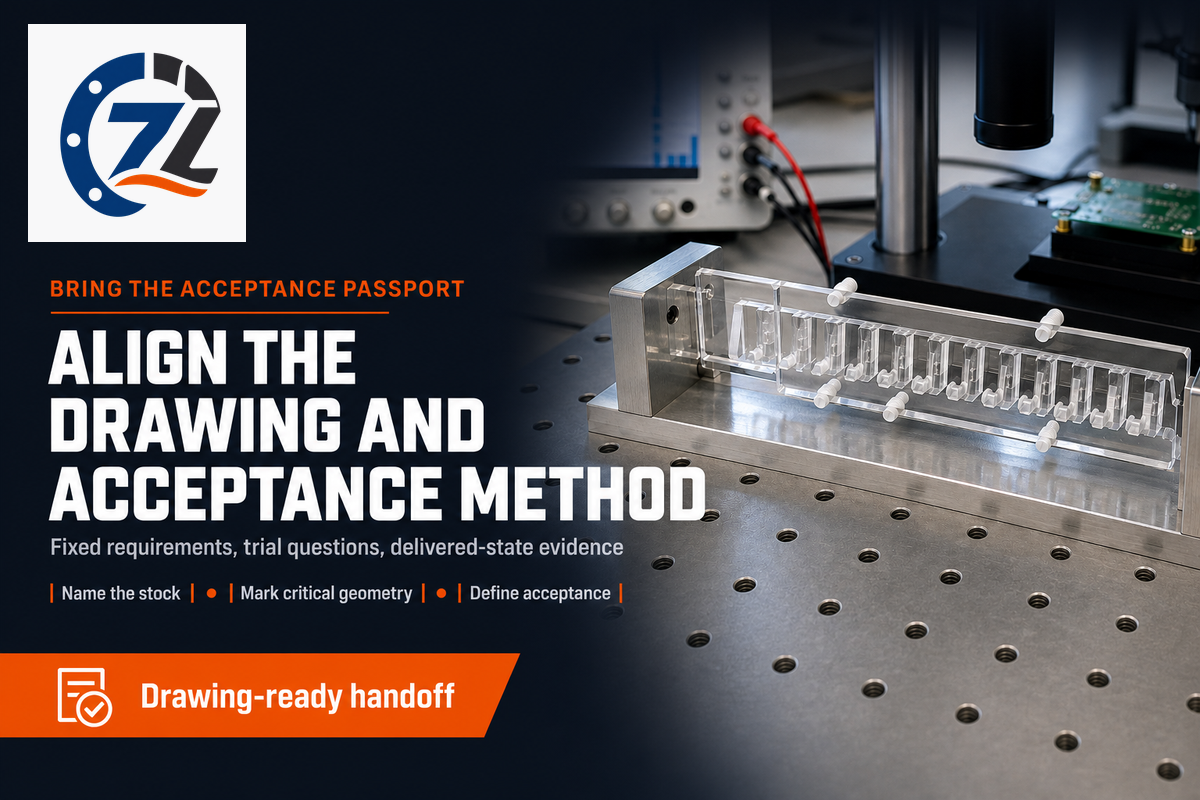
Bring the stock state, critical geometry, finish, later exposure, and inspection needs together before discussing the project. A useful discussion separates fixed drawing requirements from trial questions and identifies the delivered-state evidence needed for acceptance. For dimensional evidence, keep the measurement state explicit. Keep each acceptance method explicit, measurable, and tied to the intended function.
References & Sources
- Yan et al., PMMA high-speed micromilling temperature and surface study, Polymers (2020).
- Yan et al., machining and alcohol effects on crazing in regular and oriented PMMA, open full text (2023).
- Sucularli and Simsek, strategy-dependent micro-milled PMMA wall deviation, open full text (2025).
- ASTM D4802-16(2024), general-purpose acrylic sheet scope.
- ASTM D1003-21, haze and luminous transmittance test-method scope.
- Doiron and Beers, NIST dimensional metrology monograph.
- OSHA combustible dust guidance.
- Lucca et al., ASME ultra-precision cutting review.
- Bu et al., PMMA dust ignition and flame-spread experiment, Journal of Hazardous Materials (2019).




ZHENLING / MADE-TO-PRINT MANUFACTURING
From Engineering Question to RFQ-Ready Drawing
Zhenling supports custom flanges, valve bodies, rolls, bent pipe, and profiled machined parts for industrial buyers. Our engineers review the drawing, material condition, tolerance stack, quantity, and inspection requirements before the machining route is quoted.
START WITHDrawing · Sample · Critical dimensions
DEFINEMaterial · Quantity · Tolerance · Certification
DRAWING / MATERIAL / TOLERANCE
Prepare Your Part Brief
- PART INPUT
- 2D/3D drawing or sample
- PROCESS REVIEW
- Machining · forming · welding · inspection
- RESPONSE ROUTE
- Submit the website inquiry form
We use your details to review and respond to the enquiry. See our Privacy Policy.


