Get in touch with Zhenling Company


Updated August 2026 · Buyer guide based on cited sources and the recorded project brief
A CNC turning project should be evaluated as a route from controlled design inputs to accepted parts, not as a promise attached to a machine name. This guide helps design engineers and quality teams decide what must be turned, what may need another process, and what evidence connects the drawing to inspection.
That distinction matters.
A CNC turning service is a manufacturing route in which programmed tools cut a rotating workpiece, and the agreed inspection plan determines whether the finished part is accepted.
A CNC turning guide is a design-and-inspection reference that covers the basics of CNC turning as a manufacturing process. Computer numerical control coordinates machine and tool motion, but understanding turning still requires the buyer to follow geometry, workholding, datum transfer, and inspection as one connected route.
In practical terms, a CNC turning machine is a CNC machine that rotates stock while a programmed tool removes material. Using a CNC lathe can efficiently produce cylindrical parts and other axis-centered machine parts, but the desired shape alone doesn’t establish the complete machining operation. The CNC turning process still has to account for setup access, datum continuity, inspection, and any work that moves to another machine.
CNC turning rotates a workpiece while controlled cutting tools form round features. A sound sourcing decision also accounts for material state, off-axis features, workholding, tolerance, measurement method, production quantity, and any secondary milling, grinding, or finishing.
Quick Specs: What This Guide Decides
| Part-fit question | Which features favor turning, milling, live tooling, grinding, or a mixed route? |
| Drawing question | Which dimensions, datums, threads, and surface-texture conditions are contractual? |
| Inspection question | What is the measurand, method, thermal state, uncertainty, and acceptance rule? |
| Workholding question | Which locating face, support, and datum relationships must survive each setup? |
| Surface question | Which parameter, direction, cutoff, filter, and functional area define the requirement? |
| Machine question | Which spindle, axis, support, or live-tool function does the proposed sequence actually require? |
| Transfer question | Which features move to a mill, grinder, or outside process, and which datum travels with them? |
| Failure question | Which access, stiffness, thermal, or measurement condition would invalidate the proposed route? |
| Evidence boundary | Which result verifies the feature under the drawing’s actual measurement conditions? |
TL;DR
- A mostly round part isn’t automatically a turning-only part; route each feature and setup.
- Calibration isn’t enough unless the method and uncertainty fit the feature and decision.
- Bare surface values such as Ra may hide differences in form, waviness, profile shape, and filtering.
- A reclamp can break an otherwise valid datum relationship, so map setup transfers before choosing a route.
What CNC Turning Does and Where It Fits
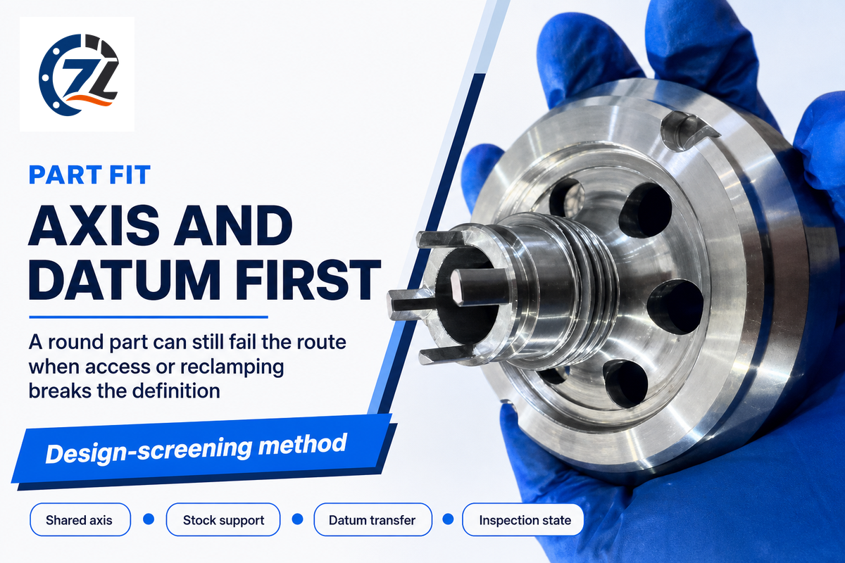
During CNC turning, material is removed while the workpiece rotates, making it a natural starting point for diameters, faces, bores, grooves, tapers, and threads around a shared axis. Part fit is still conditional: material, feature access, workholding, tolerance, surface condition, volume, and production rate can move individual features to other operations.
NIST’s manufacturing-planning abstract names material, form, shape complexity, features, dimensions, tolerance, surface condition, production volume, and production rate as planning inputs. That list is a useful corrective to the common shortcut “round part equals lathe.” Rotational symmetry is evidence for a route, not the completed route itself.
Modern CNC turning works through a CNC program that coordinates spindle speed, machine axes, and tool motion around the rotating workpiece; a bar feeder may automate stock delivery to a turning centre, while a CNC turning center without that equipment still follows the same geometry and datum logic.
The Datum-Transfer Failure Audit
Five practical questions expose where a turning route can lose the design: Do the critical surfaces share an axis? Can the stock be supported without masking a feature? Which requirements are created in the same setup? Which relationships must survive a reclamp? Which features require a separate inspection state?
CNC turning materials: stock condition belongs in the fit test
Material families don’t define one cutting recipe or one dimensional result. Your RFQ should identify grade, product form, condition, thermal processing, substitute policy, required traceability, and any secondary operation. These inputs change tool wear, deflection, thermal behavior, stock allowance, and inspection planning before they change the sales description.
Machining-material choices span metal and plastic parts, yet a material-family label doesn’t resolve final use. Metal parts may need hardness, thermal-processing, traceability, or corrosion resistance requirements; an aluminum CNC job can raise different stock, distortion, finish, and inspection questions. Product form matters too: bar, tube, forging, and casting don’t enter a turning machine with the same allowance or residual-stress history.
Zhenling reports experience with carbon and alloy steels, stainless grades, aluminum alloys, and nickel-alloy families. That list is useful for starting a material review, but it doesn’t approve a grade for pressure, temperature, corrosion, hardness, or cyclic loading. Drawing- and application-specific review still control the decision. For a material-focused follow-up, see these stainless-steel machining considerations.
Applications of CNC turning include shafts, bushings, threaded bodies, plugs, and other CNC turned parts organized around an axis. Complex parts remain candidates only when their off-axis features, support, and inspection access can be assigned without hiding a second route.
CNC Turning, Milling, and Mixed-Process Routing
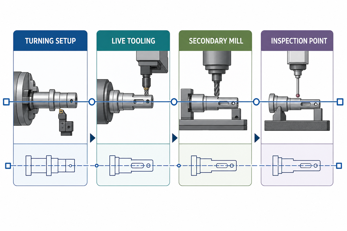
A route combining CNC turning and milling still depends on feature-level choices, not competing labels for an entire part. One component may begin on a CNC lathe machine, add cross-features on a live tooling lathe, move to a mill for inaccessible geometry, and finish with grinding or a separate surface process. Continuity across setups controls whether that sequence preserves the design.
Turning and milling can share one datum plan, but milling and turning don’t become interchangeable labels. CNC turning differs because the workpiece rotates; a milling machine normally rotates the cutter, and milling and drilling operations often handle the flat surface or cross-features that a turning setup can’t reach. Different types of CNC equipment can perform multiple operations, yet the drawing still governs which operation belongs where.
NIST’s feature-based process-planning record supports thinking in manufacturing features and process plans. The practical inference is to compare the sequence attached to the process plan, including where a feature is made, which datum survives the transfer, and where it’s inspected. Don’t approve a route from the phrase “multi-axis capability” alone.
Map Each Feature to Setup and Inspection
This hidden bottleneck map turns a part drawing into a route ledger. It’s deliberately more detailed than “turning versus milling” because a lower-setup route can still lose if it restricts tool access, distorts the workpiece, or moves inspection away from the functional datum.
- List the critical features — identify diameters, bores, faces, threads, cross-holes, flats, grooves, and functional surfaces.
- Assign the likely operation — turning, boring, drilling, live-tool milling, secondary milling, grinding, or finishing.
- Group operations into setups — record the locating face, chucking/support method, and feature access.
- Mark datum transfers — show which functional relationship must survive each reclamp or workstation move.
- Attach inspection points — define when and how each critical feature is measured.
- Name outside processes — state ownership of thermal processing, coating, grinding, or other subcontracted work.
- Compare quoted sequences — check whether suppliers priced the same route, evidence, and change-control boundary.
CNC milling vs turning: which route does each feature need?
Choose the process per feature. Turning normally starts the route when functional geometry is rotational and accessible from a stable turning setup. Milling becomes more likely for broad planar faces, pockets, asymmetric patterns, or features whose access and datum chain are clearer on a mill. Mixed parts can use both, and the route should name the setup transfer. Zhenling’s CNC milling service route for nonrotational features is a separate commercial review path.
The advantages of CNC control are most useful when the selected equipment, program, workholding, and verification plan fit the feature sequence. CNC turning centers, a basic turning machine, and a mill-turn platform can all produce parts, but they don’t offer an interchangeable variety of CNC access. The process plan should name which CNC parts are made in each setup, where precise machining depends on datum continuity, and whether a claimed lathe turning route includes a separate mill or grinder.
Turning Operations That Change Feasibility

Turning operations change more than cycle time. Facing establishes axial references; boring adds tool-reach and measurement constraints; grooving concentrates force on a narrow tool; threading adds form and gage requirements; live tooling adds off-axis access. Each operation should be tied to workholding, datum, tool, and inspection consequences.
A turning setup may combine multiple CNC turning operations, but every turning operation still has a separate access and verification consequence. Drilling operations and other types of operations can share the spindle orientation while using different tools, feeds, chip-control needs, and inspection methods.
Common types of CNC turning include basic turning, step turning, contour turning, and taper turning. These types of turning solve different feature relationships, while the advantages of CNC turning are strongest when rotational features dominate the cutting process; advanced turning systems can add access, and manual turning still depends more heavily on operator control.
An authored Cutting Tool Engineering workholding article explains that turning commonly locates from a primary face during the first operation and a machined face during later operations. It also warns that clamping, heat, and the relationship between geometrical elements can change results. That’s why the workholding line belongs in an RFQ for difficult parts.
CNC Turning Tolerances, Surface Texture, and Drawing Strategy
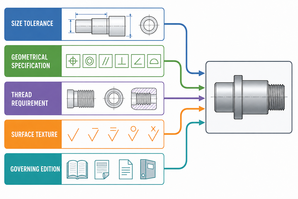
Quote-ready turning definitions separate size tolerances, geometrical specifications, thread requirements, and surface texture instead of hiding them inside one general note. Contract documents should identify the governing publication and edition, place tighter controls only where function needs them, and state enough measurement conditions for supplier results to be compared.
Units should travel with every controlled value. For notation only, “25 mm diameter,” “0.8 µm Ra,” and “20 °C reference temperature” show complete value-and-unit pairs; they aren’t recommended specifications or supplier capability claims. The actual value, symbol, tolerance, measurement direction, and reference condition must come from the approved design definition.
A CAD file helps communicate geometry, but it isn’t automatically the complete CNC machining design authority. The drawing or model-based definition should identify units, revision, datums, tolerances, threads, surface requirements, and the rule that governs conflicts. That controlled package lets precision machining and precision turning decisions follow function instead of a generic website capability table.
ISO’s official 2768-1:1989 catalogue page says the publication was reviewed and confirmed in 2022 and remains current. Future ISO 2768 is under publication at stage 60.00 and is expected to replace it. Until a contract adopts the replacement, “future” is not “already in force.”
ISO 22081:2021 addresses general geometrical and general size specifications, while ISO 21920-1:2021 addresses indication of profile surface texture. Citing the catalogue scope does not reproduce the standards or make them automatic requirements. Purchase documents must invoke the applicable edition.
📐 Engineering Note
A general tolerance note is a fallback for dimensions without individual indications. It isn’t a reason to leave functional diameters, runout, threads, sealing surfaces, or measurement conditions ambiguous.
Why a bare Ra value may not be comparable
A Quality Magazine article using examples supplied by metrology manufacturer Mahr Federal separates form, waviness, and roughness, and shows that two visibly different profiles can share one Ra value. Buyers should therefore state the parameter, value and units, measurement direction, cutoff or filtering condition, evaluation length where relevant, and functional area. Suppliers can then confirm the method rather than guessing from “smooth finish.”
CNC Turning Inspection and Acceptance Planning
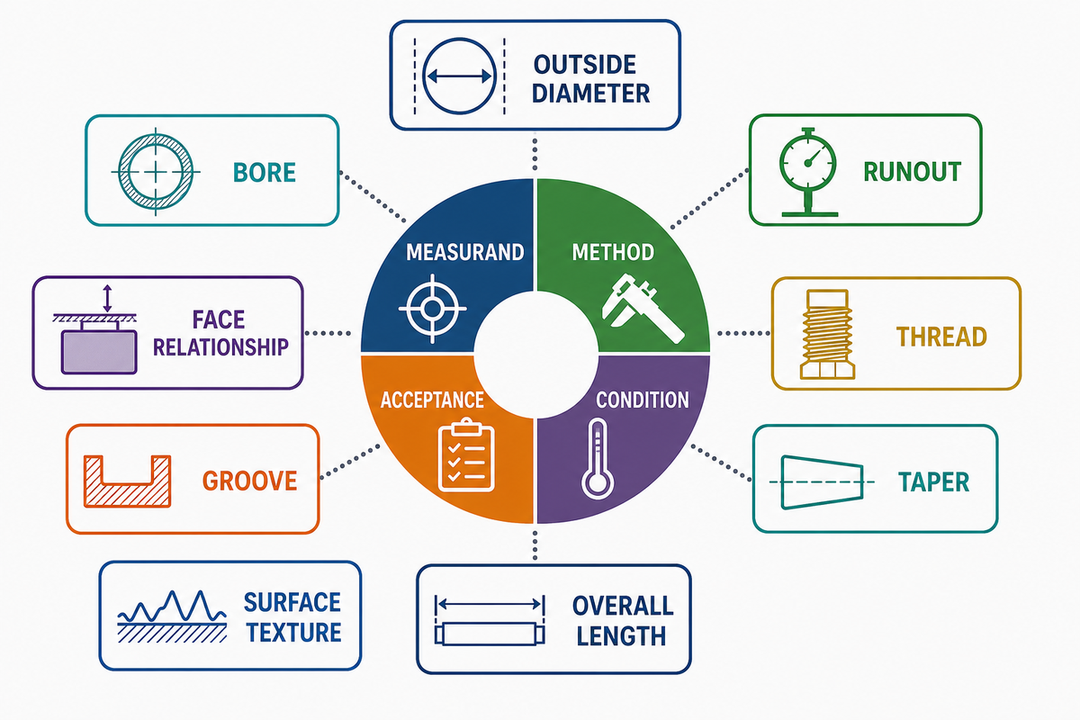
Inspection planning starts by defining the quantity intended to be measured, then selecting a method whose model, resolution, uncertainty, access, and thermal conditions fit that quantity. Calibration records support traceability, but buyers still need a decision rule that explains how results near the specification limit are handled.
That choice becomes especially important when a diameter, taper, thread, surface texture, and datum relationship must be accepted in different measurement states, because a calibrated instrument can still answer the wrong question if its contact model, alignment, temperature, or decision rule does not match the drawing.
JCGM VIM 2.41 Note 5 states that metrological traceability doesn’t by itself show that uncertainty is adequate for a purpose or that mistakes are absent. NIST likewise asks what the instrument actually sees, not only what the operator intends to measure.
“We generally aim to test our instruments with measurements akin to those that the instruments will be used for.”
The 9-Field Measurement Method Matchboard
Complete one row per critical feature. “Calibrated CMM” or “micrometer inspection” isn’t a full plan; the row must connect the feature definition to its thermal state, method model, uncertainty, and acceptance decision.
| Feature type | Define the measurand | Candidate method question | Condition / decision field |
|---|---|---|---|
| Outside diameter | Size at stated section(s) | Contact points, force, alignment, resolution? | Part/reference temperature; uncertainty; limit rule |
| Bore | Diameter, form, or both | Reach and contact model? | Depth locations and thermal state |
| Runout | Circular or total runout to named datum | Datum simulation and rotation? | Setup and decision rule |
| Face relationship | Perpendicularity/axial location | How is the datum established? | Clamping and temperature |
| Thread | Pitch diameter/form/class | Functional gage or measured result? | Gage status and accept/reject rule |
| Groove | Width, depth, radii, location | Can the probe reach without bias? | Sampling and method agreement |
| Taper | Angle, diameters, length, contact, or fit | Which representation controls? | Reference and decision rule |
| Surface texture | Parameter and functional area | Direction, stylus/optical method, cutoff/filter? | Evaluation length and acceptance rule |
| Overall length | Endpoints and reference faces | Contact/alignment and temperature? | Thermal correction if applicable |
The NIST temperature-uncertainty publication identifies part temperature and thermal-expansion coefficients as contributors to dimensional uncertainty away from the 20 °C reference. This doesn’t mean every shop report must include a laboratory-grade uncertainty budget. It means a critical measurement plan should state whether thermal state matters and who owns the correction or conditioning requirement.
Limitations and Hidden Route Changes
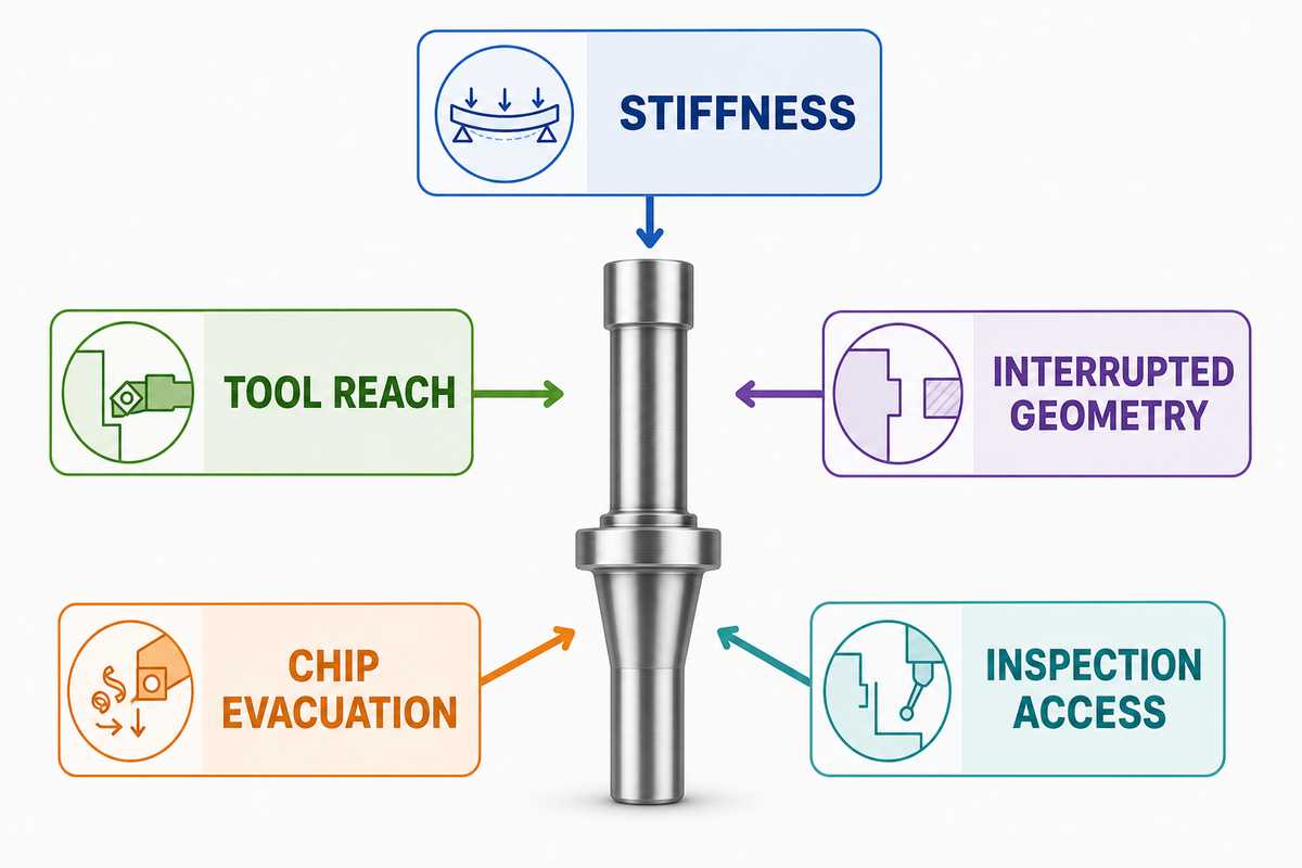
CNC turning loses its apparent simplicity when stiffness, tool reach, interrupted geometry, chip evacuation, or inspection access becomes the controlling constraint. Even a rotational part may require added support, another setup, a mill, grinding, or a different stock strategy. Honest routing names those handoffs before pricing.
Peer-reviewed 2025 slender-shaft research links low rigidity to bending during cutting and models the interaction among cutting force, clamping, shaft geometry, deflection feedback, and diameter error. It doesn’t establish a universal length-to-diameter limit. Ask how the proposed support and sequence were validated for this material and geometry.
What are the downsides of CNC turning?
CNC turning is less attractive when critical geometry is mostly nonrotational, off-axis access dominates, slender sections deflect, deep internal features restrict tools or gages, interrupted cuts disturb stability, or a second process controls final accuracy. These conditions don’t make turning “bad”; they change the feature/setup sequence and the evidence needed to release the part.
When NOT to buy a turning-only route
- Don’t accept “turning only” when critical flats, pockets, cross-holes, or datum relationships require an unquoted secondary setup.
- Don’t accept a slender-shaft limit stated without material, unsupported length, diameter, support, cutting force, and validation context.
- Don’t accept “surface finish included” when parameter, value, area, direction, filtering, and pre/post-finish state are missing.
- Don’t accept a universal tolerance band as proof that the quoted inspection method fits each critical feature.
Frequently Asked Questions
These CNC machining FAQs address the method and sourcing evidence behind a custom CNC decision. They don’t replace drawing-specific feasibility review or create a general promise for every material, tolerance, or quantity.
What is CNC turning?
CNC turning rotates a workpiece while controlled tools create diameters, faces, bores, grooves, tapers, threads, and other axial features around a shared axis during machining.
CNC turning is a subtractive machining process in which the workpiece rotates while cutting tools move along controlled paths. It commonly creates diameters, faces, bores, grooves, tapers, and threads. Rotational geometry makes turning a likely starting route, but cross-features, workholding, material state, inspection access, and secondary processes still decide the complete plan.
How is CNC turning different from milling?
Turning rotates the workpiece, while milling normally rotates the cutter against a held workpiece; mixed parts may need both processes and more than one setup.
Turning is efficient for features organized around a rotational axis, while milling is flexible for planar, pocketed, or asymmetric geometry. Modern turning centers may add live tooling, so the processes are not always separate. Route features and setups individually, then compare tool access, datum continuity, workholding, inspection, and batch economics before selecting a sequence.
What tolerances can CNC turning hold?
No single tolerance describes every turned feature because geometry, material state, workholding, thermal state, production route, and measurement method all change the achievable result in the released part.
Capability depends on feature size and geometry, material state, workholding, machine condition, tool access, thermal state, production route, and measurement method. Put function-driven tolerances on critical features and ask the supplier to confirm the route and evidence for those features. Do not use a general website tolerance as order-specific proof.
Which materials are suitable for turned parts?
Many metals and plastics can be turned, but the exact grade, product form, condition, hardness, service environment, traceability, geometry, and inspection requirements determine the route.
Material review should include grade, product form, condition, hardness or thermally processed condition, stock availability, substitute policy, service environment, and required traceability. Nominal families can behave differently across conditions, batches, stock sizes, and prior processing. A bar, forging, casting, or tube can enter the lathe with different allowance, distortion, and traceability questions. Confirm geometry, tolerance, surface requirements, secondary processes, inspection state, and approved substitutes with the exact material line. This prevents a familiar alloy label from becoming a false promise about machinability or final-part suitability.
Does a passing first article prove that production is stable?
A passing first article proves the inspected item under one revision and route; it doesn’t prove process behavior, repeatability, or controlled change across later production releases.
Production release may also require controlled revisions, repeatable workholding, process monitoring, inspection cadence, tool-change rules, nonconformance handling, and reapproval triggers. Required evidence depends on buyer risk and contractual requirements; no universal sample count applies to every turning order.
Design guide and commercial page boundary
This article owns geometry, datum transfer, drawing definition, surface texture, and inspection method. The commercial page separately handles order-specific capability and quotation scope.
Why This Guide Separates Method from Capability
Company and material-family context is based on first-party information recorded in the project brief. External NIST, JCGM, ISO, peer-reviewed, and disclosed trade sources support the buyer methods. No machine list, certification statement, or general tolerance is converted into proof for a particular order.
Related Articles
- CNC machining service routes — start at the process-family hub.
- Rapid CNC prototyping — separate learning parts from production release.
- Precision CNC machining evidence — examine definition and measurement boundaries.
- Carbon-steel machining inputs — prepare grade, condition, and inspection questions.
References & Sources
- Preliminary Design and Manufacturing Planning Integration — National Institute of Standards and Technology.
- Feature-based Process Planning Based on STEP — National Institute of Standards and Technology.
- Defining Workholding Setups — Cutting Tool Engineering.
- ISO 2768-1:1989 Catalogue Record — International Organization for Standardization.
- Future ISO 2768 Catalogue Record — International Organization for Standardization.
- ISO 22081:2021 Catalogue Record — International Organization for Standardization.
- ISO 21920-1:2021 Catalogue Record — International Organization for Standardization.
- Surface Finish Measurement Basics — Quality Magazine; examples credited to metrology manufacturer Mahr Federal.
- VIM 2.41: Metrological Traceability — Joint Committee for Guides in Metrology.
- Measurement Uncertainty 101 — Quality Magazine; quoted practitioner employed by metrology-instrument supplier Pratt & Whitney Measurement Systems.
- Uncertainties in Dimensional Measurements at Nonstandard Temperatures — National Institute of Standards and Technology.
- Analytical Modelling of Parallel Multidirectional Cutting of Slender Shafts — International Journal of Mechanical Sciences.
- Assessing Process Stability — National Institute of Standards and Technology.