
Get in touch with Zhenling Company

High-Volume CNC Machining relies on a controlled CNC machining process to manufacture repeated quantities of parts across production runs. Scaling that process means managing the cost of accepted output, available production time, and changes during tool life. A short prototype cycle time is a starting point; repeat orders require a process that integrates through inspection, finishing and shipping.
By CYH · Updated October 2026
Before increasing the release quantity
Separate annual demand from each production batch. Compare quotations at the same accepted quantity and finished condition. Calculate machine output with each loss counted once, then check the downstream route. Use time-ordered production results to set the monitoring and release plan.
In the machining industry, differences in viewpoint are connected when emphasis is placed on the production route. A production engineer thinks about cycle and tool life records; a buyer needs a consistent cost scope; the quality team thinks about measurement. Keeping the views integrated simplifies scheduling large quantities of parts without hiding rejects, queues or recurring setup work. The benefits of CNC machining become useful in practice when the planned route can be performed at the required cost and speed, which determines the value machining provides.
What High-Volume CNC Machining Means in Practice
High-volume CNC machining refers to reliable, repeated production. This is organized production focused on a known family of part types, a planned release schedule and reusable process controls. Consider quantity, cycle time, design stability, and the work required after cutting. The machining needs are defined by the annual demand, batch size and delivery frequency.
A different set of concerns exists for physical dimensions. Large part CNC machining services focus on the size of the workpiece, its handling and machine travel; large machining focuses on those physical constraints. A program to make thousands of small pins may require very little space compared to large part machining, which may involve a program for a short run of large, heavy housings. Even with a small order quantity, moving large parts with large diameters may require special handling. In modern manufacturing, state dimensions and quantities separately: manufacturing large quantities does not necessarily require large workpieces.
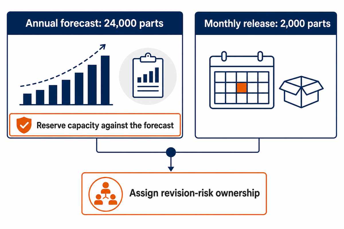
Example: a buyer forecasts 24,000 parts per year but wants 2,000 parts delivered monthly. Producing all 24,000 parts in one campaign would reduce the number of setups, yet it also places more stock at risk if the drawing changes. Setting up and inspecting first-off work remains necessary when production is planned and scheduled. The production agreement must include release size, a forecast horizon, and a rule for engineering changes. A shop planning for CNC equipment around the total annual production can reserve the wrong capacity or purchase excess material. A definition of high volume is the repeated workload the complete route must support.
In Miller’s discussion on production-machining, he emphasizes the importance of planned tool wear and offsets, and the need to standardize processes. These practices become recurring work when production continues beyond the first setup. For an unstable design, low-volume machining can create a route before larger releases.
A forecast of 24,000 parts and a release of 2,000 parts describe different commitments. Create a recurring setup plan for the release, reserve capacity against the forecast, and assign ownership of stock exposed to a revision. Combining these into a single “high volume” label provides no guidance for repeat production. Handling large order volumes starts with an agreed release schedule.
CNC Milling, Turning and Swiss Machining: Match the Part
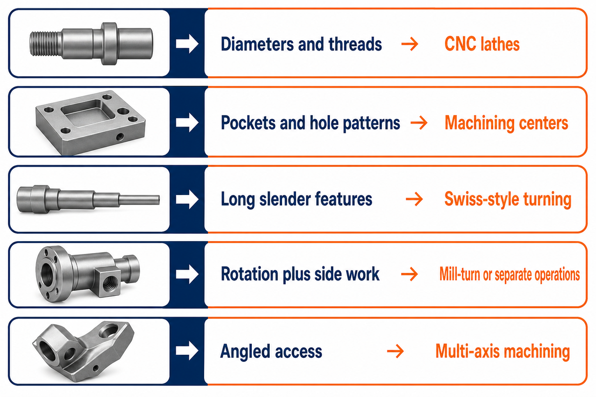
Select the type of machining based on the surfaces to be finished and how the workpiece can be supported. CNC turning is suitable for rotational features. CNC milling can reach flats, pockets and other off-axis features. Mixed features can be combined on separate machines, or on a suitable multitasking platform. The batch quantity can affect fixture design, part loading and scheduling.
In Behandish and colleagues’ process-planning research, turnable surfaces and non-turnable features receive different machining operations. That is a useful way to review complex parts: a shaft with cross-holes can need both a lathe and a mill. The question is, how can each feature be cut to preserve its relationship to the rest?
| Part feature | Candidate route | Production question |
|---|---|---|
| Diameters, faces and axial threads | CNC lathes | Can stock feed and part transfer maintain location? |
| Pockets, planar faces and hole patterns | Machining centers | Which faces locate each repeated setup? |
| Long, slender turned features | Swiss-style turning with suitable support | Can the bar, guide bushing and cutting zone work together? |
| Rotational features plus side work | Mill-turn or turning followed by milling | Does combined processing reduce a troublesome transfer? |
| Several angled access directions | Multi-axis machining | Does the extra access remove setups without weakening support? |
The table is a method for route screening, not a machine specification. Whether the setup works still depends on the condition of the material, how chips are removed, and the access of the tool. When CNC turning services and milling services are compared, consider what operations they represent, including CNC vertical milling or CNC boring. Detailed drawing and datum preparation is covered in the CNC milling design and inspection guide.
Is Swiss Machining the Right Choice for Your Project?
Swiss machining is a good option to consider for long, slender turned parts that require close support to the cut. A guide bushing reduces the unsupported length as the part advances. Other features may be completed with live tools or a secondary spindle, depending on the sequence of operations represented by the machine.
“The fact that the tools are so close to the guide bushing helps with rigidity.”
Some Swiss machines also perform milling work. Likewise, 5-axis CNC machines can decrease transfers on a suitable part, but additional axes won’t remove loading time, tool changes, or inspections. Compare multi-axis CNC machines with the complete feature set rather than by axis count. The useful machining capabilities are operations and access directions that machining offers and this drawing actually needs.
Design Choices That Survive High-Volume Production
A production-ready design gives functional features the control they need and leaves accessible cutting and measuring paths. Tight tolerances, thin sections and awkward internal corners can add work on every cycle. Address those details with the design owner before committing to fixtures, because a small recurring delay will accumulate across high-volume production runs.
Mark the features that affect fit, sealing or motion. Different functions require different aspects of a bore. Alone, diameter readings don’t provide info on other aspects of a bore. Set burr and surface texture requirements on the drawing if they impact assembly. Otherwise, a fast cutting cycle can become a slow deburring or sorting job. Give the requirements for parts or components in their delivered condition, including later processing.
Example: a nonfunctional detail adds 30 seconds of handling to each of 2,000 parts. That’s 60,000 seconds, or 16.7 hours, before any allowance for interruptions. Removing the feature is a design decision, not an operator shortcut. If a detail is required, then time must be recovered through a different means while maintaining the requirement. The repeated labor for a one-off prototype is hidden by the small total quantity.
Workholding changes the final part result. A thin wall can deflect under clamping force and spring back after release. A part that measures correctly while held in place can still change after release. Machinists discussing tight production bores raise support, cleanliness and clamping as practical checks. Define a state of measurement instead of treating another shop’s reported tolerance as a guarantee.
For components with tight tolerances, the production package should connect each critical characteristic to its machining step and measuring method to control precision and quality. Resolve both prior to freezing the repetitive process.
CNC Machining Cost: Compare Cost per Accepted Part
To compare high-volume machining costs, take the agreed batch cost and divide it by the quantity released using the agreed-upon acceptance method. Separate launch costs from recurring costs and trace what happens to parts that are rejected or reworked. Comparing costs using a route structure requires the same denominator. Apply that same scope when comparing CNC machining services for high-volume production.
How do you calculate machining cost for CNC machines?
Add material costs and cutting costs to the quote for setup, tooling, inspection and secondary operations and divide by the accepted quantity. Keep costs that are outside of the manufacturing quote (bought-in freight, duty, and inventory costs) separate. Add them only once when comparing the broader purchase.
The Good-Part Cost Bridge
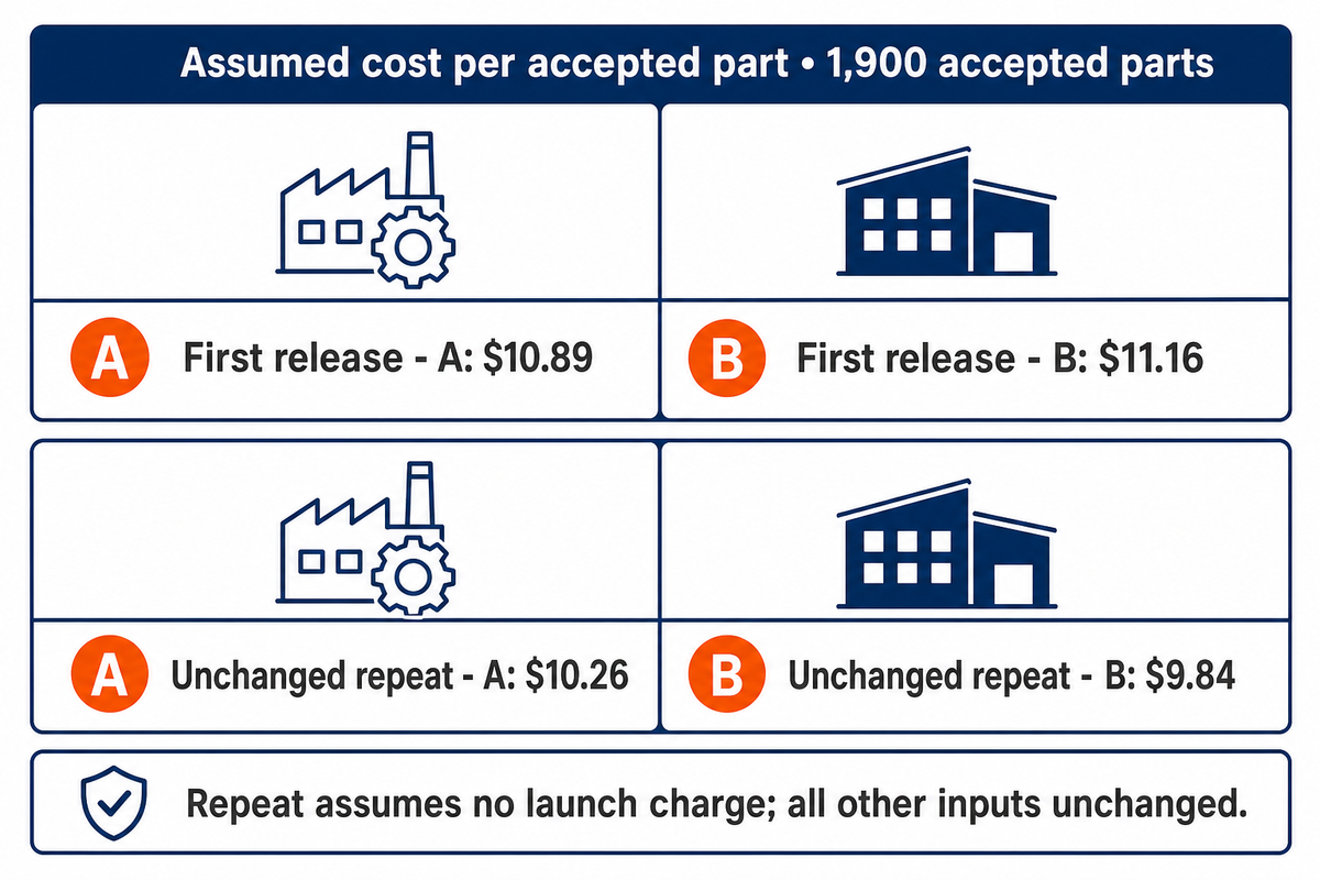
Assumed inputs: It’s assumed that two shops started 2,000 parts to the same drawing and released 1,900 parts each. Each shop completed 1,850 parts on the first pass, 50 parts were accepted after rework and 100 parts were scrapped. Both shops quote the same finish and inspection scope. Although supplier B had a lower cutting-and-material rate, the first-order cost estimate increased because of a larger launch charge.
| Cost or quantity field | Supplier A | Supplier B |
|---|---|---|
| Quantity started | 2,000 parts | 2,000 parts |
| First-pass output | 1,850 parts | 1,850 parts |
| Reworked and accepted | 50 parts | 50 parts |
| Accepted quantity | 1,900 parts | 1,900 parts |
| One-time launch charge | $1,200 | $2,500 |
| Material and cutting, per started part | $8.00 | $7.50 |
| Material and cutting, total | $16,000 | $15,000 |
| Finishing, accepted parts only | $2,850 | $2,850 |
| Inspection charge | $300 | $500 |
| Packing charge | $150 | $150 |
| Additional rework charge | $200 | $200 |
| First-release total | $20,700 | $21,200 |
| Cost per accepted part | $10.89 | $11.16 |
Calculation: Supplier A is ($1,200 + $16,000 + $2,850 + $300 + $150 + $200) ÷ 1,900 = $10.89 per accepted part, rounded. Supplier B is $21,200 ÷ 1,900 = $11.16. A is lower for this release despite B’s $0.50 lower cutting-and-material rate. The rework charge covers additional work only; the original cutting cost is already included.
On an identical repeat order with no launch charge and every other input unchanged, A becomes $19,500 ÷ 1,900 = $10.26 per part; B becomes $18,700 ÷ 1,900 = $9.84. That reversal is why recurring charges and fixture ownership belong in the commercial agreement. Paying a tooling line doesn’t automatically transfer title to the tool.
Accepted quantity represents quantity released based on the agreed-upon inspection plan, which may include sample inspection. It isn’t a count of individually verified defect-free items. The example doesn’t consider the cost of freight, import duties, and the cost of capital tied up in stock. For this, use the Landed cost calculator separately. EPA’s cellular manufacturing guidance shows how long batches may reduce marginal production cost while building waiting inventory and incurring carrying costs.
Production Capacity: Follow the Bottleneck, Not the Spindle
Estimate production capacity by considering available time and the complete repeat cycle before committing to a high production rate. Likewise, consider the actual output of the part and the capacity of downstream operations before setting a shipment target. Machine output and route output differ when inspection, heat treatment or finishing queues build up, and an average output rate alone does not establish a reliable delivery time.
How do you calculate CNC machining time?
Take the time required for one complete repeated cycle, including loading and unloading, if those activities keep the machine idle. Record set up and long stops separately. Dividing actual run time by the time required for one cycle gives attempted output for that period; applying first-pass yield gives the quantity completed without rework.
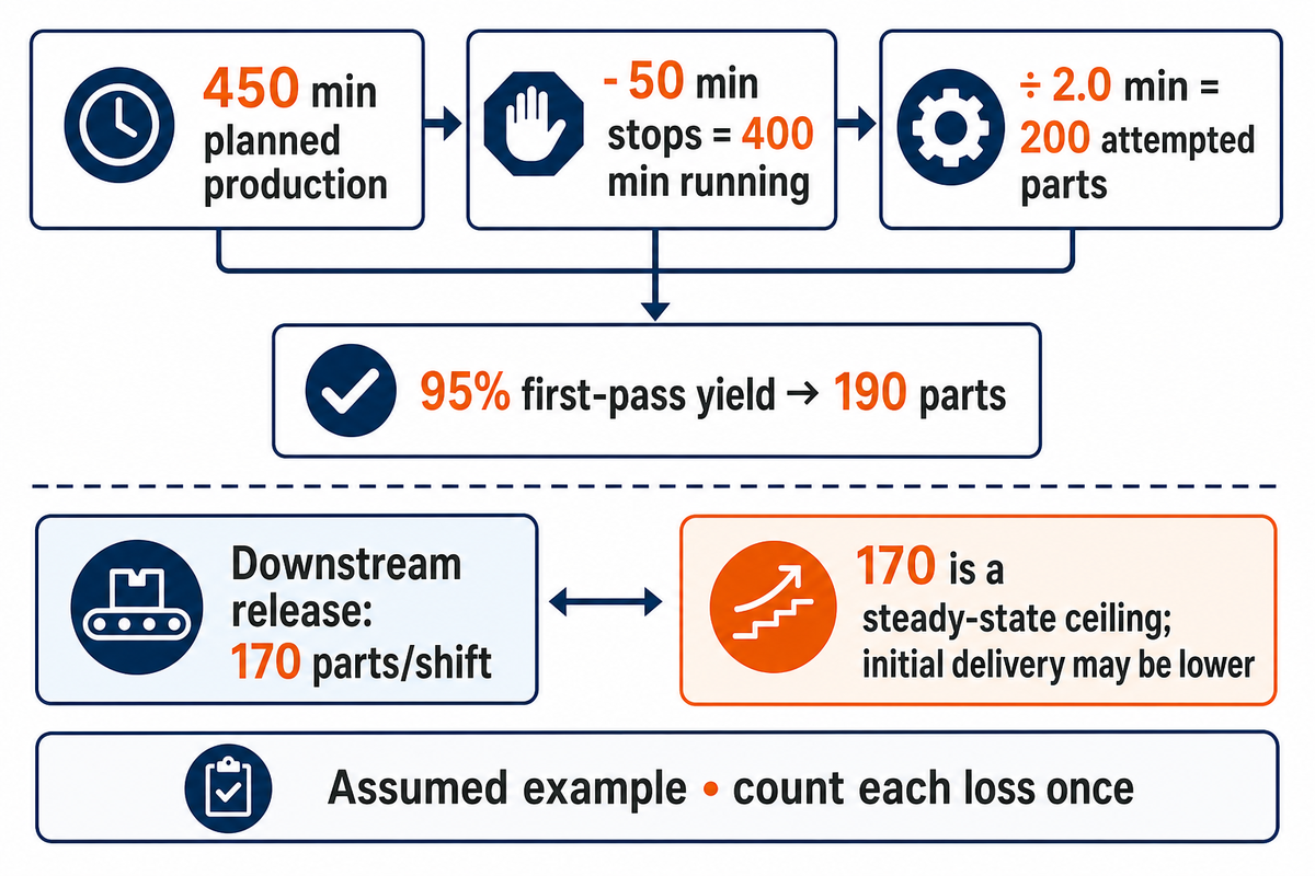
Example: an 8-hour shift contains 480 minutes. Remove 30 minutes of planned breaks to obtain 450 minutes of planned production time. Setup and other recorded stops consume 50 minutes, leaving 400 minutes. An observed 2.0-minute cycle, including the blocking load/unload work and minor cycle delays, produces 200 attempted parts. At 95% first-pass yield, the result is 190 first-pass parts. Any later recovered rework belongs in a separate output and time record.
Vorne’s equipment-effectiveness method shows similar results with ideal cycle time, availability, performance and quality. Assuming an ideal cycle time of 1.8 minutes, availability is 400 ÷ 450, performance is 1.8 ÷ 2.0 and quality is 0.95. Their product is 0.76, so 450 ÷ 1.8 × 0.76 = 190 parts. Multiplying the already adjusted 190 parts by 0.76 again would deduct the same losses twice.
A hidden bottleneck map for repeat orders
| Loss class | Record | Who acts | Decision |
|---|---|---|---|
| Material readiness | Usable stock and release date | Planning | Schedule only released material |
| Changeover | Last-good to next-first-good time | Production | Separate setup from repeat cycle |
| Loading and transfer | Blocking handling time per cycle | Manufacturing engineering | Compare fixture and transfer methods |
| Cutting and small stops | Observed cycle distribution | Production | Retain the delays included in the rate |
| Tool servicing | Tool changes, offsets and lost time | Tooling | Set intervention points from production data |
| Deburring and washing | Completed parts per available hour | Cell leader | Balance work with machining output |
| Inspection and rework | First-pass, held and recovered quantities | Quality | Keep release and recovery queues separate |
| Outside processing | Batch windows and returned quantities | Purchasing | Reserve the external process slot |
| Packing and dispatch | Released packed quantity by cutoff | Logistics | Base shipment commitments on ready goods |
The map shows an editorial planning worksheet. In Modern Machine Shop’s Kinetic Company case, heat-treatment furnace scheduling shapes production planning.
If deburring and inspection together release only 170 parts per shift, machining 190 first-pass parts creates a potential 20-part queue. Under comparable steady-state conditions, 170 parts is the route’s output ceiling; startup, transfers and variation can reduce the first shift’s delivery. Glasserman and Wang’s network research also distinguishes utilization from the constraints on meeting demand within a fixed lead time. Schedule a tested route and its variability, not just a spindle average.
Quality Control: Prove Stability Across the Batch

Production quality control links an appropriate measuring system with time-ordered process readings and a defined batch-release decision. Each answers a different question: whether a feature can be measured consistently, how the process behaves over time, and whether the submitted lot meets its acceptance plan. Each of these informs a different part of the process and lot-release decision. Keeping these questions separate helps maintain quality across repeat orders.
To improve production while maintaining quality, we need to know how each reading leads to an action. A claim of “quality and precision” gives neither a measuring method nor a release rule. For stability throughout the machining process, we need evidence across the operating conditions used in a run, including restarts and tool changes.
NIST’s gauge-study guidance covers repeatability, reproducibility and other effects on measurements. Look for those things in the instrument, method and parts condition. An example is a narrow bore measured while warm at the machine and measured later after it cooled. In this case, a controlled comparison of the two readings is necessary before either becomes a process correction signal.
For ordinary capability indices, NIST compares an in-control process with specification limits. Chronological readings reveal trends that a pooled histogram can hide. Tool changes, restarts and offset adjustments should stay attached to those readings. Serial dependence also matters: NIST’s autocorrelation paper addresses cases where successive observations aren’t statistically independent.
Assumed inputs: a 10.000 ± 0.020 mm diameter, a stable normal process with mean 10.006 mm, and population standard deviation 0.003 mm. The tolerance width is 0.040 mm. Cp = 0.040 ÷ (6 × 0.003) = 2.22, while Cpk = min(10.020 − 10.006, 10.006 − 9.980) ÷ (3 × 0.003) = 1.56. In this case, the smaller value of Cpk shows mean shift toward the upper limit. Production estimates also carry sampling uncertainty; these example values aren’t universal acceptance thresholds.
Process behavior (control) limits and specification limits are different. Replacing one with the other can turn ordinary variation into repeated unnecessary adjustments. ISO 7870-2:2023 provides guidance on Shewhart control charts. Choose a control chart and an appropriate sampling method for the process and data, rather than arbitrarily determining the number of consecutive pieces and drawing limits.
Do
- Retain time order and intervention events.
- Match the measurement method to the feature.
- Use the agreed lot-release rule.
Don’t
- Pool unlike setups into one unexplained index.
- Treat more readings as automatically independent data.
- Equate sampled lot acceptance with full inspection.
Acceptance sampling allows a conclusion about a lot being acceptable. NIST’s sampling plan definitions describe the risk of accepting an unacceptable lot. Determine the sampling plan with the customer and usage requirements. A first article, a capability study and a shipment release should have distinct records.
Tool Wear, Chips and Rework: Control Repeating Losses
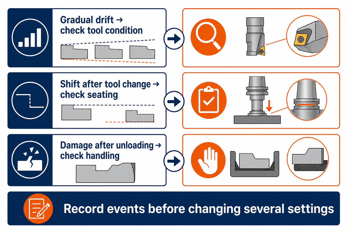
Examine repeated machining defects by relating the symptom to the time and process event. Gradual dimensional drift, abrupt changes after tool replacement, and damage occurring after unloading suggest different checks. Note the condition of the tool, offset, and fixture, as well as the affected quantity, before adjusting several things at once and losing the comparison.
Wear changes the cutting edge and its contact with the workpiece. Chipping can produce a sudden failure; built-up material can disturb the cutting action; chips trapped near a locating surface can alter the next setup. Sandvik’s technical material distinguishes cutting tool wear and failure mechanisms. A critical review of milling tool wear monitoring from 2026 identifies and correlates wear modes with measurement and sensor technologies.
Machine time is money. Example: the first parts after a tool change shift in diameter, while the earlier readings had drifted gradually. The readings could also be out of spec because of gradual wear; record the tool-change point and check tool seating under the job’s control plan. Taking a new reading with the established measuring method would help identify the cause. There are many suggestions to help you identify the problem area. One suggestion is to check whether, after changing a tool, the spindle taper is covered with swarf. This helps to identify problems related to tool seating. The suggestions help to identify the issues; however, the hold interval and correction authority must come from the job’s control plan.
The same discipline is needed for automation. For example, producing parts with minimal human intervention needs a response to tool failure, a buildup of chips, empty stock, or a failed measurement. A sister tool can extend running time only when its offsets and changeover behavior are controlled. Sometimes the fastest way to remove the most material may lose to a cycle that limits stoppages. To handle high-volume work, record the normal cycle time and the response to interruptions; produce large quantities under the agreed controls without compromising precision.
In the example of the 2,000 part release, each additional 15 seconds of routine handling adds 8.3 hours. Distinguish that repeated loss from a tool service stop. The first requires a cycle change; the second requires a recorded intervention strategy. Combining them under “slow machining” covers up what needs to be done to recuperate capacity.
CNC Machining vs Casting or Forging for Repeat Orders
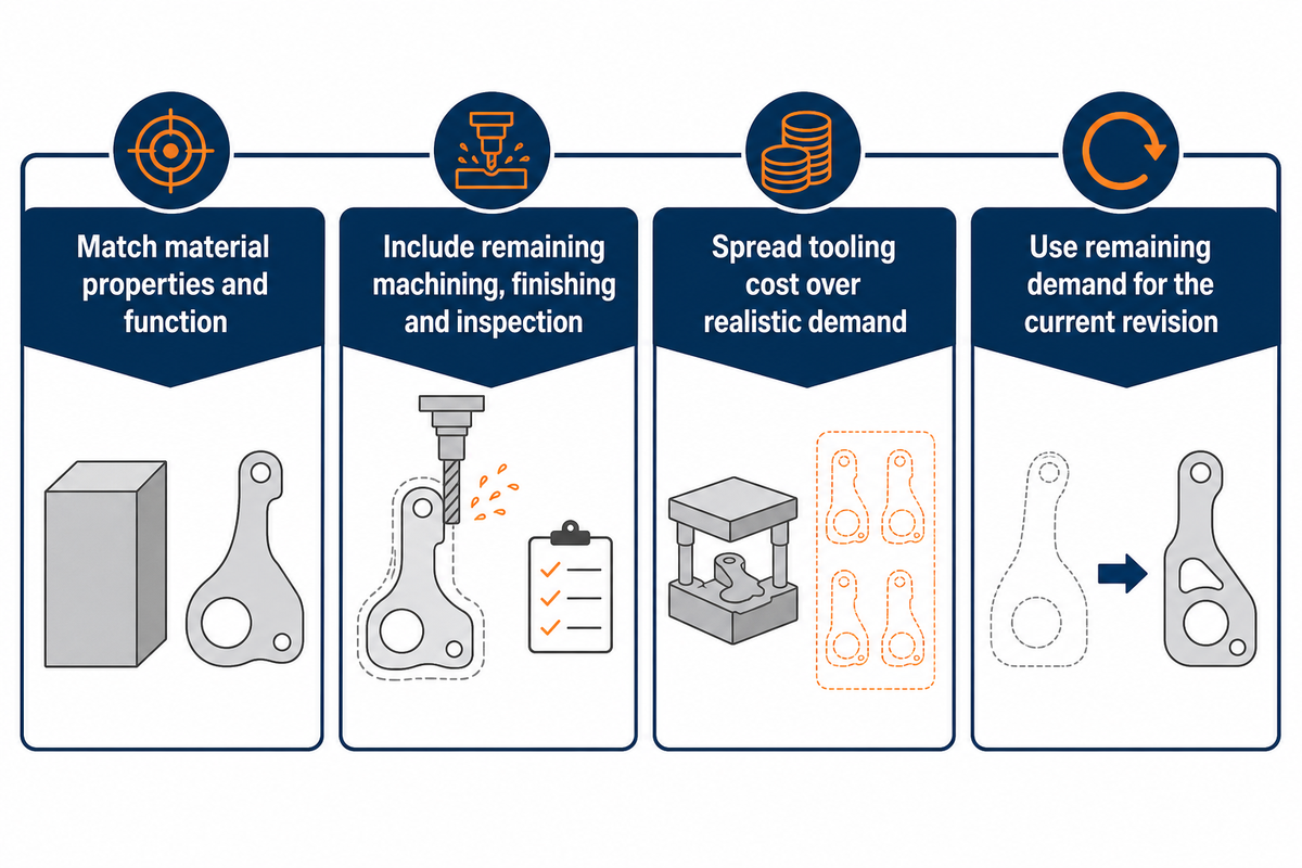
Compare machining from stock to a near-net-shape approach after matching necessary material properties and features. Preparation and recurring costs vary for manufacturing processes. Casting and forging might reduce the need for subsequent material removal, but tooling and qualification costs need to be spread over realistic demand for the released design. Consider the remaining machining, finishing and inspection that take place after the initial forming operation.
The Open University’s teaching case on gear production shows the order of decisions, since the use of zinc pressure-die casting in the lowest-cost mass production was ruled out due to strength. A cheaper approach that misses the function isn’t an equivalent to the specified part. The case’s examples of historic normalized prices shouldn’t be taken as current supplier quotations.
Consider tooling cost, material condition, surfaces still requiring machining and when the drawing is likely to change for a repeat housing. A near-net blank that removes roughing operations can be an attractive option for a number of unchanged releases. A revision that occurs in the future can strand tooling before that saving is realized. The valve-adaptor case published by the Forging Industry Association also shows that machining occurs after forming and forging.
Use remaining demand for the current revision as the comparison horizon. Mass production of components can justify preparation that a short-lived design cannot recover, but millions of parts are not a universal threshold. Keep additive routes as a separate evaluation when internal geometry or consolidation changes the design; the machining versus 3D printing guide covers that in detail. No single order quantity solves every process comparison.
Industry Outlook: Better Evidence for Repeat Production
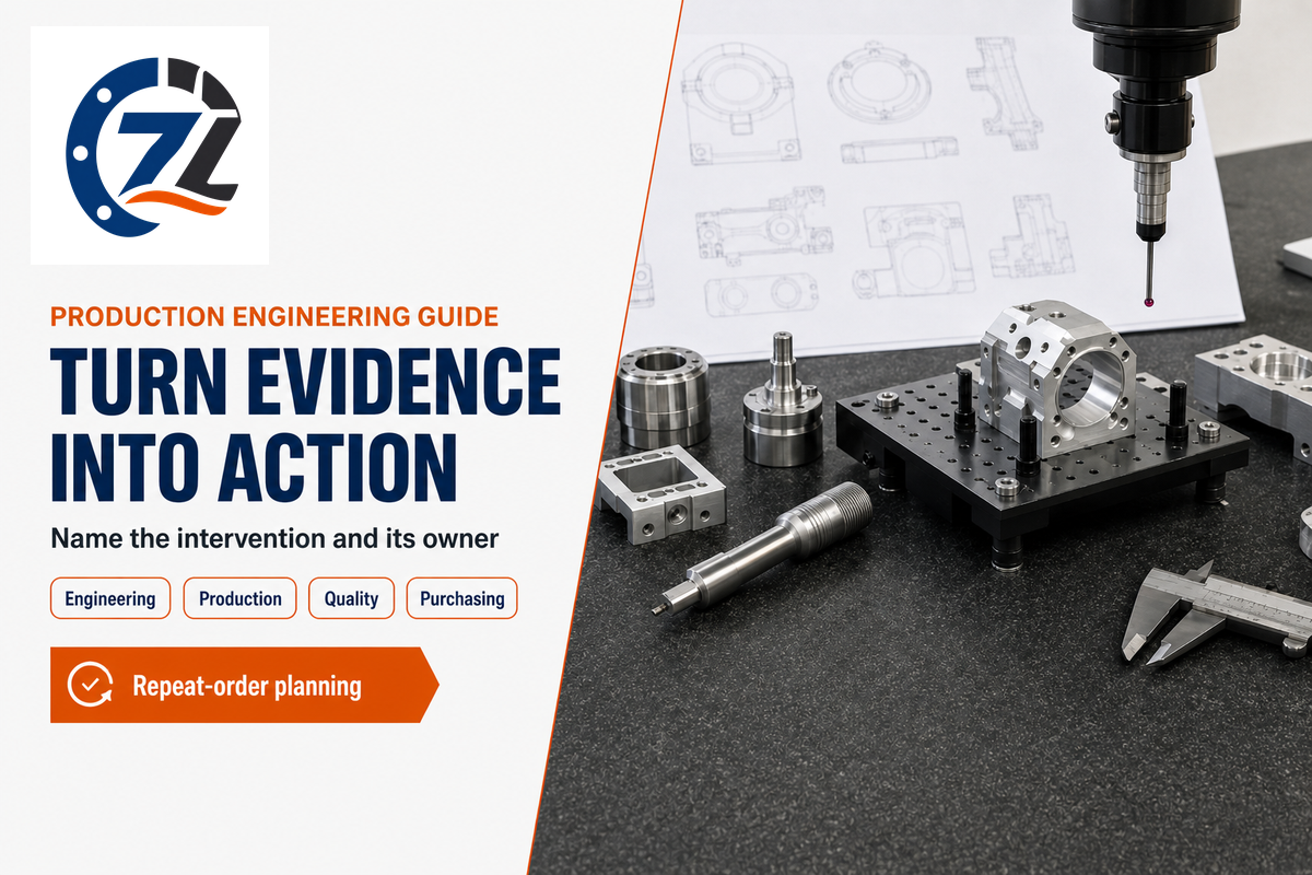
For repeat production, better connection between process measurements and release decisions provides useful direction. A current revision to an industry standard gives buyers an opportunity to re-assess how capability is calculated, while monitoring research points toward earlier wear detection. The purchasing decision remains practical: what measured change triggers an intervention, and who decides the response?
Published in February 2026, ISO 22514-2:2026 addresses capability and performance for time-dependent process models, particularly processes that do not remain in statistical control. An emphasis on time-dependent processes corrects the overly broad rule that all capability analysis methods require stable-state processes. Select the statistical model with the quality team; a pooled Cpk value should not silently stand in for a time-dependent analysis.
The July 2026 tool-wear review identified challenges of real-time reliability, transfer between operating conditions and prediction uncertainty; a production trial with tools in known states should assess false alarms and missed events. Buying advanced CNC monitoring without connecting the signal to a decision leaves the recurring loss untouched.
Release a repeat order with named owners
Use a single release record for engineering, production, quality and purchasing. The entries below connect the prototype to the intended production route without substituting a generic tolerance or sampling percentage for the drawing. Repeated machining projects require the revision, tooling and release responsibilities be carried forward together.
| Owner | Record before release | Decision it controls |
|---|---|---|
| Design engineering | Part number, revision, material condition and critical features | Which definition the repeated lot must meet |
| Production engineering | Fixture, program, tool list and restart method | How the accepted route is reproduced |
| Quality | Measurement method, time-ordered trial data and release plan | When to adjust, hold, rework or release |
| Purchasing and planning | Release quantity, outside-process slots and recurring charges | What is bought and when it is available |
Make sure the fields are completed prior to increasing release quantity, including approval authority for changes and ownership of dedicated fixtures. For a route specific review of a part, take that package to Zhenling’s high-volume CNC machining services page. When comparing machining solutions with the aforementioned package, it helps to keep the discussion to the release schedule, required inspection records and the drawing.
Frequently Asked Questions
What quantity counts as high-volume CNC machining?
Define high-volume CNC machining by the repeated workload and release schedule, then state the quantities explicitly.
Annual demand, pieces per release and cycle time belong together. An order for 2,000 parts delivered every month requires a different setup and inventory plan from a single annual campaign. Part complexity also changes the machine hours behind the same quantity. Specify these fields in the production brief instead of relying on a supplier’s volume label to communicate the workload.
What is the typical lead time for high-volume manufacturing?
Lead time is the complete route’s scheduled duration, including material, preparation, production, outside processing and release.
A repeat order with available stock and approved tooling can start from a different position than a new design. Divide the schedule into dated milestones, including the first accepted production parts and any finishing slot. A machining estimate of 400 minutes covers only the stated machine work; it leaves queue time, downstream processing and shipment preparation to be scheduled separately.
Which industries benefit most from high-volume manufacturing?
Industries with recurring demand for stable part designs benefit from repeatable routes and reusable preparation.
Automotive components, industrial hardware and selected medical or aerospace parts can fit that pattern, although their qualification requirements differ. The business benefit comes from spreading preparation across accepted output and controlling recurring work. An industry label alone says little about the suitable batch size: a revision-prone development part and an established replacement component need different release plans even within the same sector.
Does CNC machining guarantee identical parts?
No. Computer numerical control repeats programmed commands, while the physical process still varies.
Tool wear, temperature, stock and workholding influence the result. Control the variation around the required features with suitable measurements, process monitoring and a release plan. Precision CNC work still needs those controls throughout the production run.
Can a machine shop handle both pre- and post-machining services?
Yes, a shop can coordinate the wider route through its own operations or qualified outside processors.
The purchase agreement should identify who controls material preparation, heat treatment, coating, inspection and shipping. Outside processing adds its own batch windows and transport steps. A supplier arranging the work still needs a clear handoff for part identification, condition and acceptance records. Include those steps in both price and capacity comparisons, especially when a finishing operation determines the earliest shipment date. Coordination responsibility and physical ownership of the processing equipment are separate matters.
Is high-volume CNC machining worth it if the design may change?
Smaller releases are preferable when a likely revision would leave substantial finished stock or dedicated tooling unused.
Compare preparation savings against the exposure on the current revision. Freeze the functional requirements first, then increase releases as demand and the design become more predictable. Annual demand alone does not determine the economical batch.
What evidence shows that a shop has handled a similar production job?
Relevant route records and measured results show how a shop managed comparable features, material and release demands.
Useful records include a route outline, the measuring method, time-ordered results, tool-change controls and the treatment of nonconforming pieces. Customer identities can remain confidential while the shop explains its method. Compare the difficult feature and its production state, not only the nominal machine model. A short trial on the proposed route can then establish project-specific inputs for cycle time, measurement and release planning before a larger order is committed. For high-precision CNC machining, include how the machined parts were held and measured, and whether those conditions match the proposed production route.
Key takeaway
High-volume production works when the repeated route, cost denominator and release decision describe the same job. Start with a controlled part definition, count each production loss once and schedule the operations that turn machined output into accepted shipments.
About this guide
This report was prepared for Zhenling Metal using engineering references and published manufacturing cases. Numerical worksheets use stated assumed inputs. Company-specific capacity, pricing and acceptance requirements will be established in the project review.
References & Sources
- production-machining discussion
- Behandish and colleagues’ process-planning research
- Cutting Tool Engineering
- cellular-manufacturing guidance
- Modern Machine Shop’s Kinetic Company case
- Glasserman and Wang’s network research
- NIST’s gauge-study guidance
- NIST compares an in-control process with specification limits
- NIST’s autocorrelation paper
- ISO 7870-2:2023
- Acceptance sampling
- NIST’s sampling-plan definitions
- 2026 critical review of milling tool-wear monitoring
- gear-production teaching case
- Forging Industry Association’s valve-adaptor case
- ISO 22514-2:2026
These links identify the publications used in the related explanations. Practitioner accounts describe their own experience; numerical worksheets use explicitly stated assumed inputs.