Get in touch with Zhenling Company

CNC Milling Service Guide (2026): From Drawing to Inspected Part

Updated August 2026 · Engineering and procurement guide
A CNC milling service is a controlled manufacturing route that turns a product definition into inspected parts through requirement review, process planning, workholding, toolpath programming, cutting, edge and finish control, measurement, and release. Computer numerical control moves the machine tool, but the controlled route still depends on people, data, the workpiece, and measurement. The useful buying question isn’t “Which machine is fastest?” but “Which route can make and verify this part without losing its definition?”
The short version
Send one controlled model-and-drawing package, specify only function-driven tolerances, compare identical quote assumptions, and ask for part-specific inspection evidence. A longer machine list or a faster quote is not proof that the order is controlled.
| Quick specification | Buyer input | Supplier response |
|---|---|---|
| Definition | 3D model, drawing, revision | Conflict list and controlling source |
| Material | Grade, specification, form, condition | Stock basis and traceability proposal |
| Acceptance | Critical features, method, reporting | Inspection plan and decision rule |
What a CNC Milling Service Does from Drawing to Inspected Part
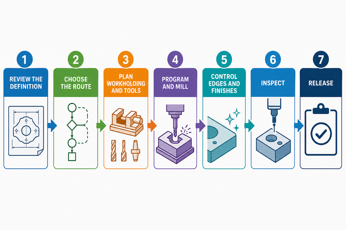
The deliverable is not spindle time. It is a released part whose geometry, material, surface condition, revision, and evidence match the agreed order. The service carries buyer intent through route planning, controlled machining, inspection, and documented release, consistent with the connected-definition principle in NIST’s digital-thread work. That chain normally has seven control points.
- Review the definition — reconcile model, drawing, purchase order, specifications, and revision.
- Choose the route — decide whether 3-axis, indexed 4-axis, 3+2, simultaneous 5-axis, or another process sequence fits the geometry.
- Plan workholding and tools — establish datums, clamping, access, tool reach, and stock allowance.
- Program and mill — create, verify, and release toolpaths with controlled offsets and setup instructions.
- Control edges and finishes — deburr, protect critical surfaces, and coordinate any specified secondary work.
- Inspect — measure the agreed characteristics in the required part state.
- Release — retain the applicable material, inspection, revision, and nonconformance records.
Early-stage gaps travel downstream. If a drawing and model disagree on a corner radius, the programmer cannot make both true. If a coating allowance is missing, a bore may be correct before finishing and wrong afterward. If “inspect all dimensions” is written without a method or sampling rule, the quote may contain a very different inspection scope from what the buyer expects.
Start with the Manufacturing Definition, Not the Machine
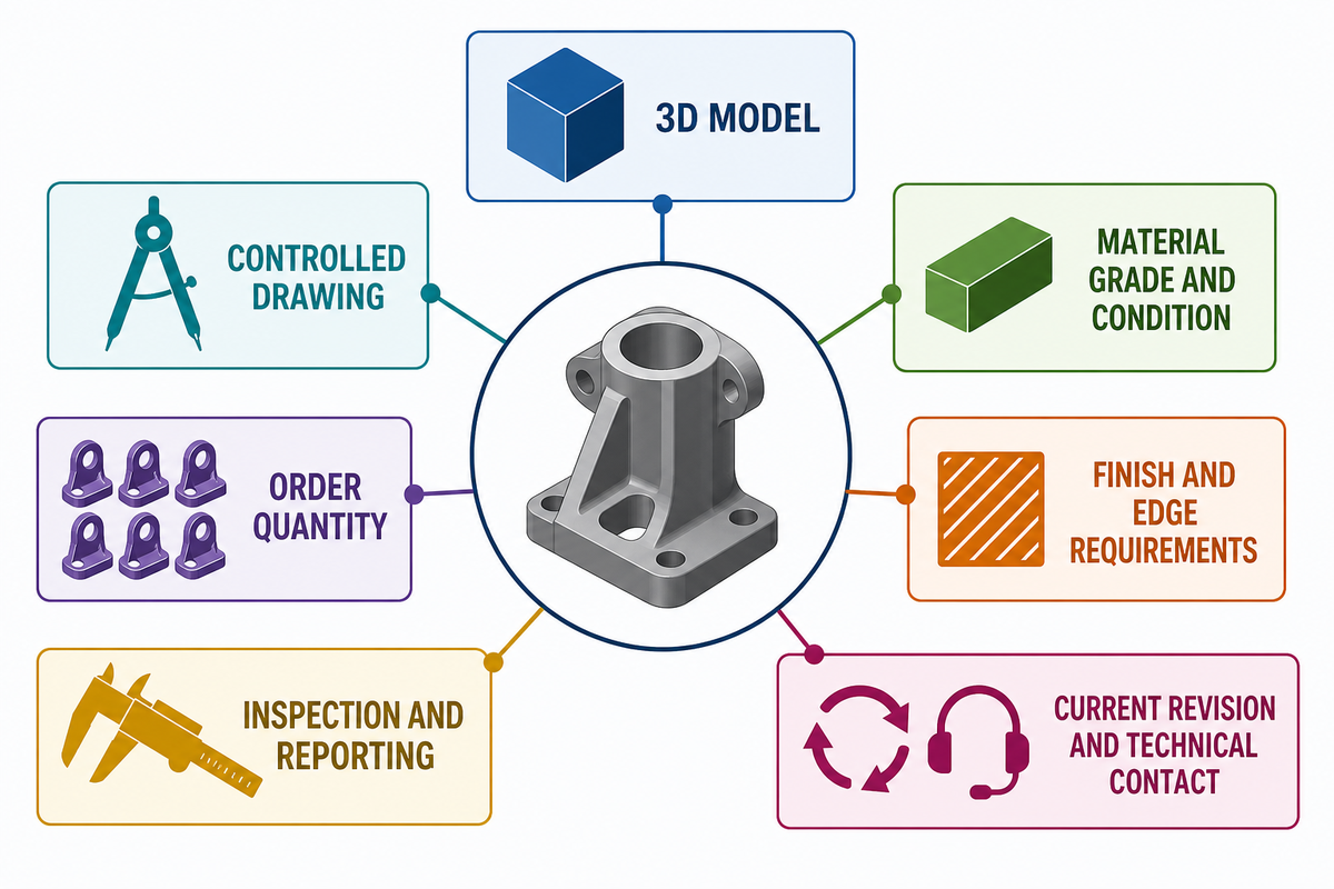
Quote-ready packages contain at least seven fields: the native or neutral 3D model, a controlled drawing, material grade and condition, order quantity, finish and edge requirements, inspection and reporting requirements, and the current revision with a technical contact. Threads, datums, tolerances, sealing faces, markings, restricted substitutions, and special-process specifications belong in the package when they affect acceptance.
The model describes shape well, but it may not define allowable variation or business rules. A CAD file is only one input to the manufacturing process for custom parts and metal parts. A drawing can state a 0.02 mm position requirement, an Ra 1.6 µm surface-texture parameter, a 0.20 mm maximum edge break, a protected face, or a certificate requirement. Conversely, an old drawing may contain legacy geometry while the newer model contains the intended profile. The supplier needs a written rule for which source controls each characteristic.
Do
- Give every released file the same revision.
- Mark critical and reference-only dimensions.
- Name the required material form and condition.
Don’t
- Assume a CAD model silently supplies tolerances.
- Mix inspection notes from an obsolete revision.
- Ask the shop to infer functional priorities from tight numbers.
Choose 3-Axis, 4-Axis, or 5-Axis by Setup Risk
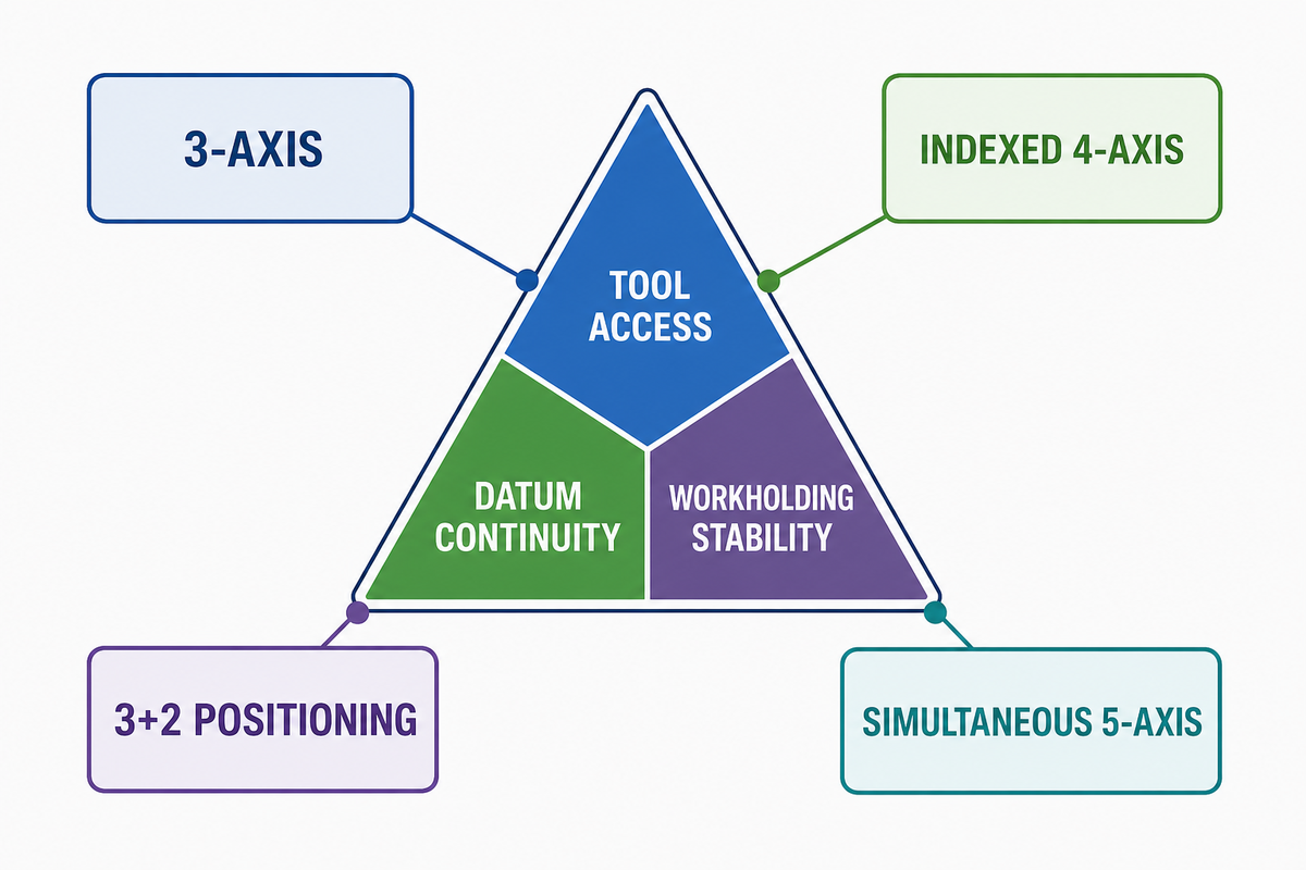
The Setup-Risk Triangle tests three things together: tool access, datum continuity, and workholding stability. More axes can expose several faces without re-clamping, but they can also increase programming, collision-clearance, fixturing, verification, and machine-performance demands. NIST’s five-axis research notes that interacting geometric and servo-control errors complicate simultaneous-motion analysis. Axis count alone therefore can’t prove accuracy.
Practical reading of the NIST evidence: fewer re-clamps may remove one error source, but they do not remove machine, control, fixture, thermal, or measurement error.
| Route | Strong fit | Setup effect | Limitation to test |
|---|---|---|---|
| 3-axis | Accessible prismatic faces, plates, pockets | May need several orientations | Datum transfer between setups |
| Indexed 4-axis | Features distributed around one axis | Reduces manual rotations | Rotary access and clamping envelope |
| 3+2 positioning | Angled faces machined from fixed orientations | Preserves one fixture for many faces | Tool length, holder clearance, datum proof |
| Simultaneous 5-axis | Contoured surfaces and changing tool vectors | Can combine complex operations | Kinematic, servo, program, and verification risk |
When not to choose five-axis: an open, stable plate with top-side pockets may be cheaper and easier to verify on a 3-axis machine. When not to choose three-axis: a part with related features on five faces may accumulate datum-transfer risk across repeated re-fixturing. The drawing and route review, not a machine badge, settle the choice.
Design Features That Change the Milling Route
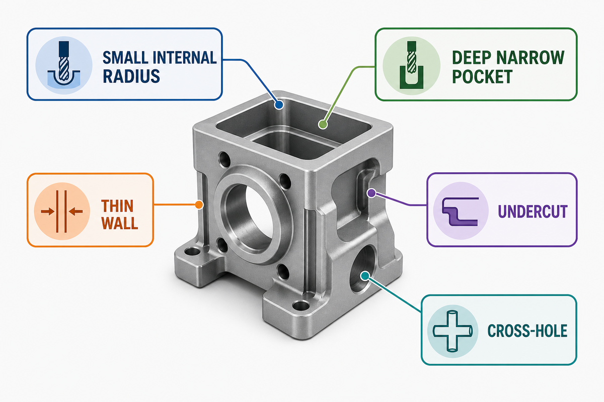
Feature geometry determines whether a tool can enter, cut without excessive deflection, evacuate chips, and leave a measurable surface. An internal radius can’t be smaller than the effective cutter path that produces it. A 60 mm-deep pocket reached with a 6 mm tool has a 10:1 depth-to-diameter relationship before holder clearance is considered; that’s a different problem from a 12 mm-deep pocket. A 1.0 mm wall can move under cutting and clamping even when its nominal model is valid. As another comparison, a 5 mm cutter at 25 mm reach, a 3 mm wall across 80 mm, and a 1 mm edge allowance each create different stiffness or finishing constraints. Multi-axis access and verification remain separate questions in NIST’s performance-test research.
| Feature | Route question | Possible response | Limitation |
|---|---|---|---|
| Small internal radius | Can a rigid cutter reach it? | Increase radius or add a local finishing tool | Smaller tools cut slower and deflect more |
| Deep narrow pocket | Is reach practical with chip clearance? | Open access, stage tool lengths, or split the design | Long reach reduces stiffness |
| Thin wall | When is material removed and unclamped? | Leave support, balance cuts, inspect released state | Residual stress is material- and geometry-specific |
| Undercut | Can a standard tool approach? | Use a lollipop, T-slot, indexed route, or redesign | Special tools add access and inspection limits |
| Cross-hole | How is breakout and burr controlled? | Sequence intersections and define edge acceptance | Hidden burrs may resist visual inspection |
| Angled sealing face | Can it be cut and measured from one datum scheme? | Use 3+2 access and a defined measurement setup | Surface texture and flatness need separate controls |
| Large flat face | What happens after clamps release? | Plan stock, clamping, stress relief, and released-state check | Machine travel does not predict final flatness |
| Micro feature | Can it be produced and verified? | Name tool, method, and measurement resolution | A model feature may be below practical evidence capability |
| Tight feature pattern | Which datum controls the relationship? | Machine related features in one controlled setup | Re-clamping can break relational control |
Allocate Tolerances, Surface Finish, and Part State to Function
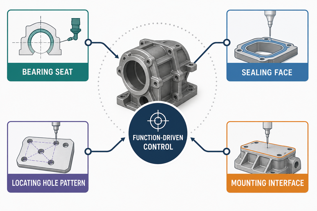
Tight tolerances should follow function. A bearing seat, sealing face, locating hole pattern, or mounting interface can justify focused control; a nonfunctional clearance face may not. Applying ±0.01 mm to every dimension increases programming, cutting, thermal-control, inspection, and nonconformance exposure without showing the supplier which relationships matter most.
General tolerances do not appear by magic. ISO 2768-1 covers certain linear and angular dimensions without individual indications, but it applies only when the drawing or governing specification invokes it. As of August 2026, ISO lists ISO 2768-1 as published with a revision under development. ISO 2768-2 is withdrawn, and ISO points to ISO 22081:2021 as the newer general geometrical specification route. State the intended document and edition; do not write an unqualified “ISO 2768” note and expect one interpretation.
Acceptance also needs a part state. Is a 0.03 mm flatness requirement checked while clamped, after unclamping, after stress relief, after coating, or at 20 °C? Is a bore measured before or after a 25 µm-per-side coating allowance? Does Ra 1.6 µm apply to the sealing track, the whole face, or a sampling path? ISO 14253-1 addresses conformity decisions near specification limits while accounting for measurement uncertainty. In practice, the RFQ question is: which decision rule will govern a result close to the limit?
Select Materials by Machining Behavior and Service Conditions
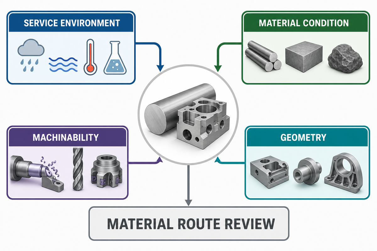
Material choice begins with the service environment, but the machining route needs more than a family name. State the applicable grade or specification, product form, heat-treatment or temper condition, and any traceability requirement. “Stainless steel” doesn’t tell the shop whether the order is 303, 304L, 316L, 321, or another grade; “aluminum” doesn’t define temper, plate condition, or residual-stress behavior.
A 2024 ASME study measured residual stress at 860 locations in a 90.5 mm-thick 7050-T7451 plate and found that inherent stress alone could push its studied high-aspect-ratio parts beyond the cited aerospace requirement after machining. That isn’t a universal prediction for aluminum. It’s a reason to ask how thin, high-removal geometries will be staged, released, and inspected.
As an illustration rather than a design rule, a 4 mm tool reaching 20 mm has a different stiffness question from the same tool reaching 40 mm; a 2 mm wall behaves differently from a 0.8 mm wall across a 50 mm span. Brass, copper, titanium, aluminium, and engineering plastics also need their own material, machinability, and route review if they enter the order. Never transfer feeds, hardness, toughness, or a machining tolerance from a family label alone.
| Family | Service question | Machining review | Limitation |
|---|---|---|---|
| Aluminum alloy | Strength, mass, corrosion, temperature | Temper, plate condition, wall stability, finish | One 7050 case cannot predict another alloy or lot |
| Carbon steel | Strength, wear, weld or heat-treatment state | Condition, hardness, scale, stock allowance | Grade label alone does not define hardness |
| Alloy steel | Load, fatigue, temperature, post-treatment | Sequence before and after heat treatment | Property values depend on form and condition |
| Stainless steel | Corrosion, cleanliness, temperature | Exact grade, work hardening, finish route | “Stainless” is not a complete specification |
| Nickel alloy | Corrosion and high-temperature duty | Tool wear, heat, rigidity, inspection access | Do not transfer generic cutting data across grades |
Understand the Quote through the Cost Stack
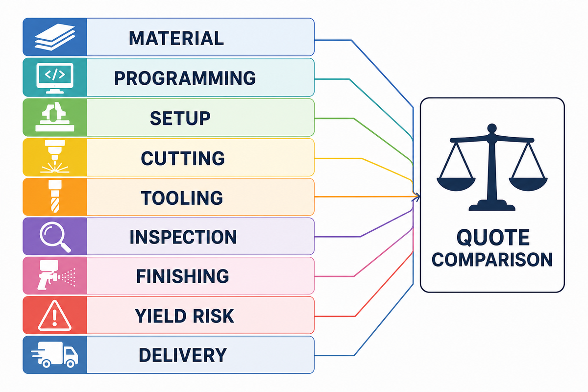
The Cost Stack separates material, programming, setup, cutting, tooling, inspection, finishing, yield risk, and delivery. Compare those assumptions before comparing totals. A low hourly rate can lose its apparent advantage if it hides four setups, a long-reach finishing operation, 100% reporting, or a high scrap exposure.
The example below is hypothetical. Each route totals 100 index points; the points aren’t dollars, market averages, or a claim about Zhenling pricing. They show how equal totals can represent different risk allocations. For a formal costing context, see NIST’s Design-for-Cost research.
| Cost element | Route A | Route B | Question |
|---|---|---|---|
| Material | 22 | 22 | Same form, condition, and allowance? |
| Programming | 8 | 14 | Standard 3-axis or verified multi-axis path? |
| Setups | 20 | 10 | How many datum transfers? |
| Cutting | 18 | 20 | What tool reach and removal rate? |
| Tooling | 6 | 8 | Any special cutters or holders? |
| Inspection | 10 | 12 | Same characteristics and reporting? |
| Finishing | 6 | 6 | Same processor and masking scope? |
| Yield and delivery risk | 10 | 8 | What uncertainty is included? |
| Total index | 100 | 100 | Equal total, different controls |
Three scenarios show why normalization matters. For a one-off fixture plate, setup and programming can dominate. For 500 repeated valve-body components, fixture repeatability, tool-life control, sampling, and yield can matter more. For a thin aerospace-style bracket, stock condition and post-unclamping inspection may outweigh nominal cutting time. Ask every bidder to state quantity breaks, included reports, outside processes, lead-time basis, packaging, and exclusions.
Move from Prototype to Production without Losing the Definition
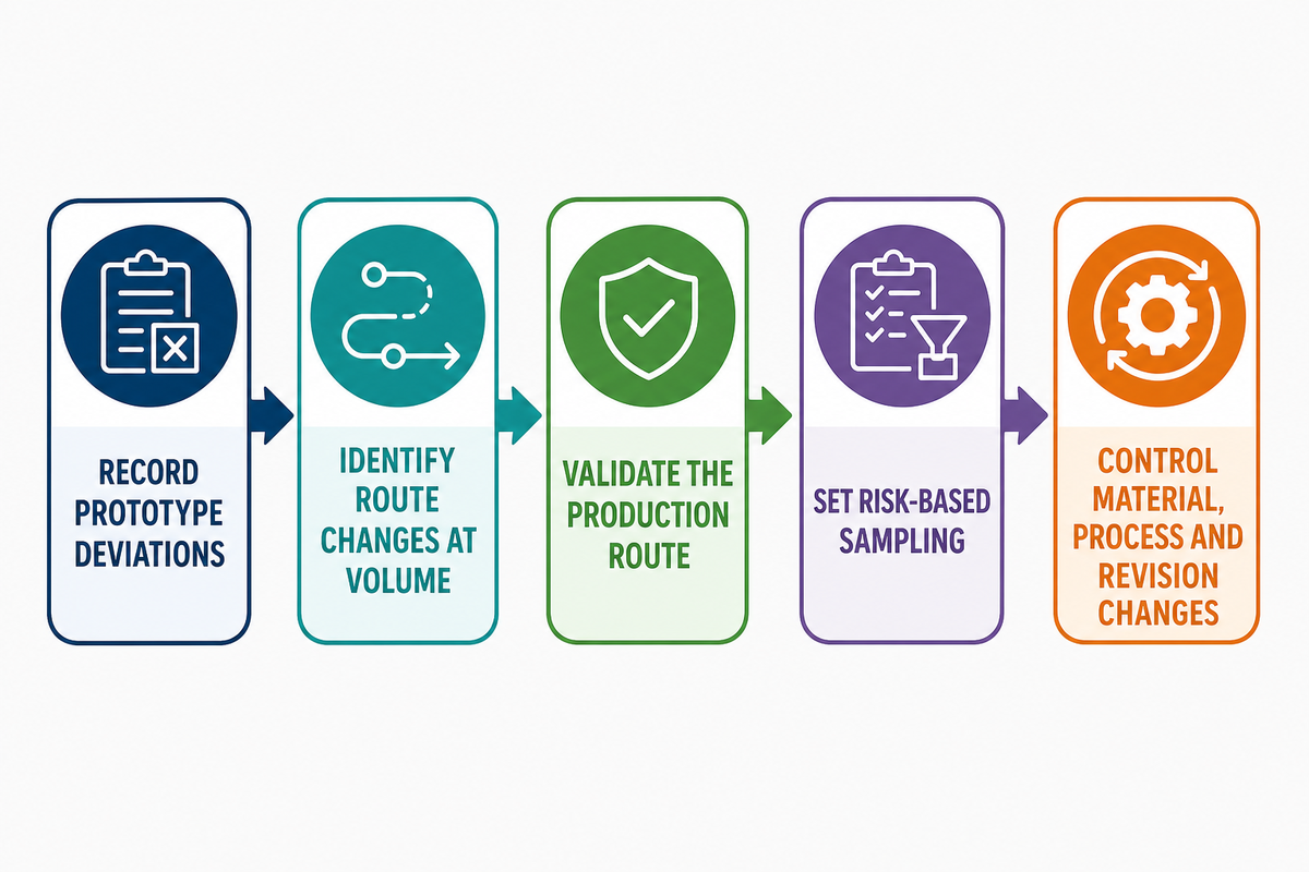
A conforming prototype proves what was observed on that inspected item. It does not by itself prove a stable production process. Production release adds a frozen revision, repeatable workholding, controlled programs and tools, material or lot identification where required, an inspection cadence, and a nonconformance path. These controls preserve the connected definition described in NIST’s digital-thread program.
- Record every prototype deviation and disposition before release.
- Identify which setup, tool, or inspection method changes at volume.
- Approve a first article or defined validation lot against the production route.
- Set sampling and reporting by characteristic risk, not by habit.
- Require written approval for material, source, process, or revision changes.
When not to scale: do not place the production order while the accepted prototype still relies on an undocumented hand correction, a temporary fixture, an obsolete model, or a measurement method that cannot be repeated.
Use the Supplier Evidence Ladder before Awarding the Order
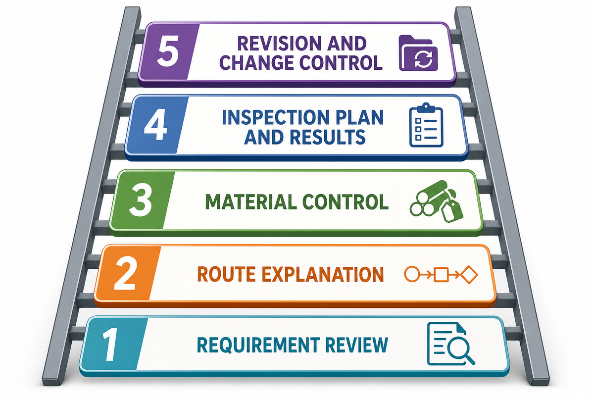
The Supplier Evidence Ladder moves from statements to order-specific proof. Each level answers a different question; none substitutes for the next.
- Requirement review — did the supplier identify conflicts, omissions, and assumptions?
- Route explanation — can it explain setups, datums, access, workholding, and special processes?
- Material control — can it identify the specified stock and preserve required traceability?
- Inspection plan and results — can it measure the actual critical features with an agreed decision rule?
- Revision and change control — can it keep the approved route aligned with the current order?
| Claim heard | Evidence to request | What remains unresolved |
|---|---|---|
| “We have five-axis machines” | Part route, fixture concept, access and datum plan | Actual machine condition and part result |
| “We are ISO 9001 certified” | Issuer, validity, sites, and certificate scope | Order-specific material and dimensional conformity |
| “We hold tight tolerances” | Feature-specific method, uncertainty, and sample result | Capability across the production lot |
| “Material is traceable” | Certificate and lot-to-part identification route | Suitability for the buyer’s application |
| “First article passed” | Controlled revision, route, report, and disposition | Long-run stability and change control |
ISO explains that ISO 9001 is a quality-management-system standard and that certification is performed by external certification bodies, not ISO itself. Certificate scope is useful management-system evidence. It is not a material certificate, dimensional report, first-article result, or declaration that every future part conforms.
Zhenling Shop Context and the Commercial Transition
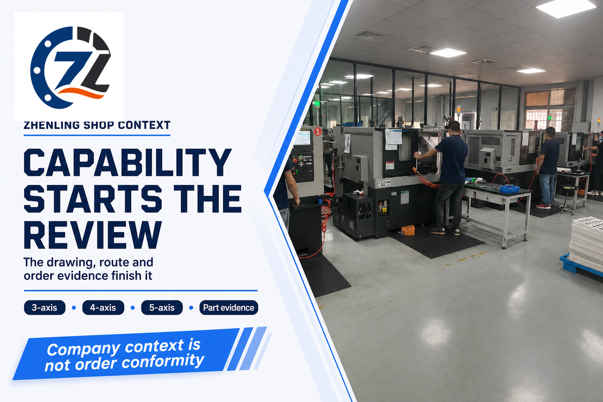
According to the company information supplied for this guide, Shanghai Zhenling Hardware Co., Ltd. was established in 2006 and operates an 8,000 m² factory with a 6,000 m² workshop in Jiashan, Zhejiang. The reported equipment mix includes 3-axis and 4-axis machining centers, imported 5-axis centers, CNC lathes, grinding and boring machines, wire-cut EDM, and radial drilling. Reported material experience covers carbon and alloy steels, stainless steels, aluminum alloys, and nickel alloys.
That inventory can begin a route-review conversation; it cannot prove that a particular 0.02 mm feature, surface-texture requirement, inspection method, or delivery target will be met. Proof remains part- and order-specific, just as ISO distinguishes management-system certification from product conformity. Buyers can first review the company’s broader manufacturing services. Once your controlled model or drawing, material condition, quantity, finish, and inspection needs are ready, review Zhenling Metal’s CNC milling service capabilities and submit the defined project for technical review.
2026 Signal: Faster Quotes Increase the Cost of Definition Gaps
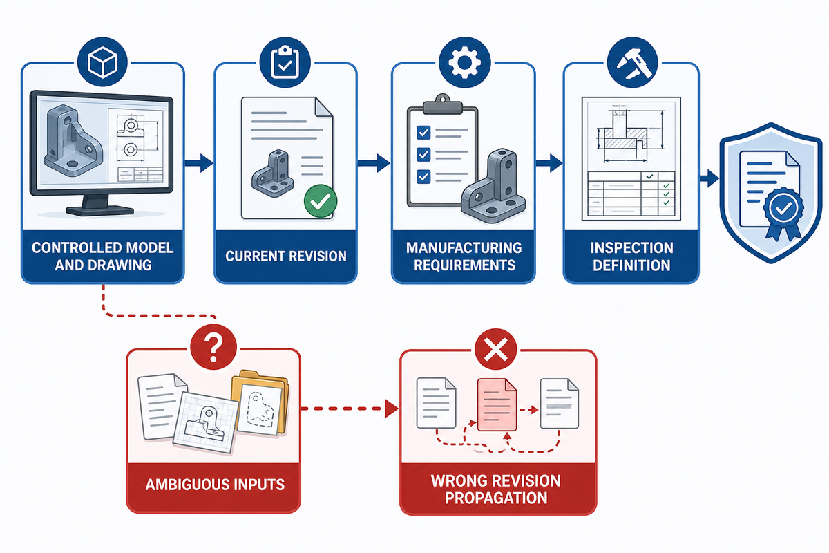
Digital quoting can shorten the time between file upload and price response, but it also makes ambiguous inputs travel faster. NIST’s digital-thread work describes the benefits of connected product definitions while identifying conformance, interoperability, data-trust, and cybersecurity needs. A wrong revision or altered model can therefore propagate beyond the quotation stage into a physical outcome. For a buyer managing repeated production, the risk is a released but wrong revision moving from quotation into programming before anyone catches the gap.
Use controlled access, revision identifiers, release approval, and file-transfer records for sensitive definitions. NIST SP 800-171 Rev. 3 is relevant where controlled unclassified information is handled in nonfederal systems; it isn’t a universal requirement for every commercial drawing. Match security controls to the actual data classification and contract.
CNC Milling Service FAQs
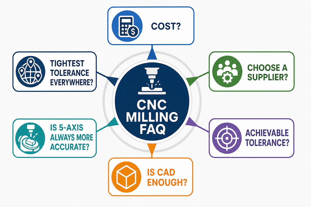
How much does it cost to get something CNC machined?
CNC milling cost depends on the whole route, including material, programming, setups, cutting, tooling, inspection, finishing, yield, quantity, packaging, and delivery requirements for the defined part.
Price depends on material and stock size, programming, setup count, cutting time, tooling, inspection, finishing, expected yield, quantity, and delivery. Setup and programming weigh heavily on a one-off part but are distributed across larger batches. Send the same model, drawing, material condition, quantity, finish, reporting scope, packaging, and delivery basis to every bidder. Then compare the Cost Stack, quantity breaks, payment basis, and exclusions instead of applying a universal hourly or per-part figure. NIST’s Design-for-Cost research provides a formal manufacturing-cost reference.
How do I choose the right CNC machining company?
Ask for evidence tied to your part.
Use the Supplier Evidence Ladder. First, check whether the company finds requirement conflicts. Next, ask it to explain the route, datums, workholding, programming, and outside processes. Then confirm material control, the inspection plan, reporting, and revision or change control. Machine ownership and a management-system certificate provide useful context, but neither proves that your actual order will conform. Prefer a supplier that states assumptions, responsibilities, change triggers, and evidence limits before award.
What tolerances can CNC milling achieve?
There is no honest machine-only tolerance answer.
Achievable tolerance depends on feature geometry and size, material condition, tool access, setup and datum scheme, machine and thermal state, cutting strategy, part state during measurement, inspection method, uncertainty, and quantity. A supplier should evaluate the critical feature on the actual part. Specify the functional relationship, datum, allowable variation, surface condition, measurement state, reporting need, sampling basis, and decision rule instead of copying a blanket tolerance across the drawing.
Is a CAD model enough for a CNC milling quote?
Usually not for a controlled order.
A model may support an estimate, but the released package often also needs tolerances, datums, threads, material condition, finish, edge treatment, quantity, revision, inspection, reporting, and any restricted substitution or special-process requirement.
Is 5-axis milling always more accurate than 3-axis milling?
No; it removes some risks and introduces others.
Five-axis milling can reduce re-clamping and improve access on suitable geometry. Accuracy still depends on machine kinematics and condition, servo behavior, workholding, tool reach, program verification, thermal state, and measurement. For an accessible prismatic part, a stable 3-axis route may be easier to control. For related features on many faces, fewer datum transfers may favor a multi-axis route.
Should every dimension have the tightest available tolerance?
No.
Tighten only function-critical relationships; leave clearance and reference features proportionate.
Where This Guide Ends and the Service Page Begins
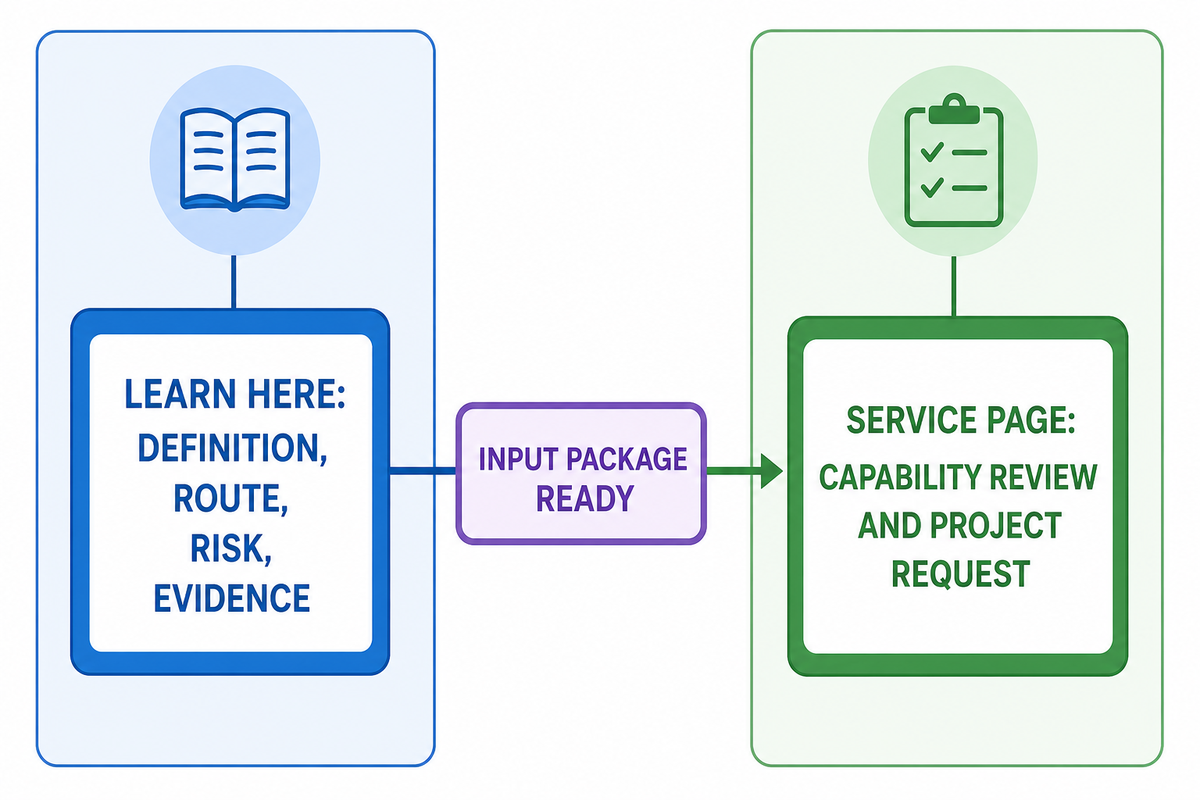
The educational article owns definition, route choice, feature risks, tolerance allocation, material questions, quote normalization, production release, and supplier evidence. The service page owns capability review and project requests. Keeping those jobs separate helps buyers learn here, then move to a commercial discussion only when the input package is ready. This people-first intent boundary follows Google Search Central’s guidance to give readers substantial, useful content rather than writing primarily for rankings.
Buyer takeaway
Freeze the definition, choose the route through the Setup-Risk Triangle, normalize the Cost Stack, and climb the Supplier Evidence Ladder before award.
References & Sources
- NIST, Virtual Machine Tool Evaluation for Standardized 5-Axis Performance Tests
- NIST, Digital Thread for Manufacturing
- NIST, SP 800-171 Revision 3
- NIST, Design-for-Cost research
- ISO, ISO 2768-1 catalogue record
- ISO, ISO 22081:2021 catalogue record
- ISO, ISO 14253-1:2017 catalogue record
- ISO, Certification and conformity assessment
- ASME Journal of Manufacturing Science and Engineering, Effects of Aluminum Plate Initial Residual Stress
- Google Search Central, Creating Helpful, Reliable, People-First Content
Research transparency: This guide combines current NIST and ISO pages, an original ASME study, same-day search research, and company information supplied by Zhenling Metal. Company facts are attributed and are not treated as independent proof of order capability. Competitor pages informed gap analysis but are not cited as technical evidence. The Cost Stack is a hypothetical teaching model, not a quotation or market benchmark.


ZHENLING / MADE-TO-PRINT MANUFACTURING
From Engineering Question to RFQ-Ready Drawing
Zhenling supports custom flanges, valve bodies, rolls, bent pipe, and profiled machined parts for industrial buyers. Our engineers review the drawing, material condition, tolerance stack, quantity, and inspection requirements before the machining route is quoted.
START WITHDrawing · Sample · Critical dimensions
DEFINEMaterial · Quantity · Tolerance · Certification
DRAWING / MATERIAL / TOLERANCE
Prepare Your Part Brief
- PART INPUT
- 2D/3D drawing or sample
- PROCESS REVIEW
- Machining · forming · welding · inspection
- RESPONSE ROUTE
- Submit the website inquiry form
We use your details to review and respond to the enquiry. See our Privacy Policy.


