Get in touch with Zhenling Company

ABS CNC Machining: A Decision Guide for Custom Parts

Pragmatic, process-based guidance for engineers, prototype teams, and buyers
ABS CNC machining is most useful when the part definition, stock condition, cutting response, and inspection state are treated as one decision—not as a generic plastic recipe. Acrylonitrile butadiene styrene is a thermoplastic family, but the label “ABS” does not establish a universal feed rate, tolerance, surface finish, or service-life claim for every workpiece.
The short version
Name the grade and stock form, establish a controlled trial, read the chip and the part together, define the inspection condition, and send a complete handoff before asking a supplier to quote. This guide explains the decision process; it does not replace facility safety review or material validation for service exposure.
Scope boundary: This is a part-quality machining guide. It does not assess airborne particulate, combustible dust, ventilation, ignition, exposure, or facility controls. Those matters require an environmental health and safety review. Nor does it determine environmental stress cracking or chemical compatibility. Those decisions require material validation for the named grade, stress state, contact medium, temperature, duration, and acceptance condition.
When Is ABS CNC Machining the Right Process?
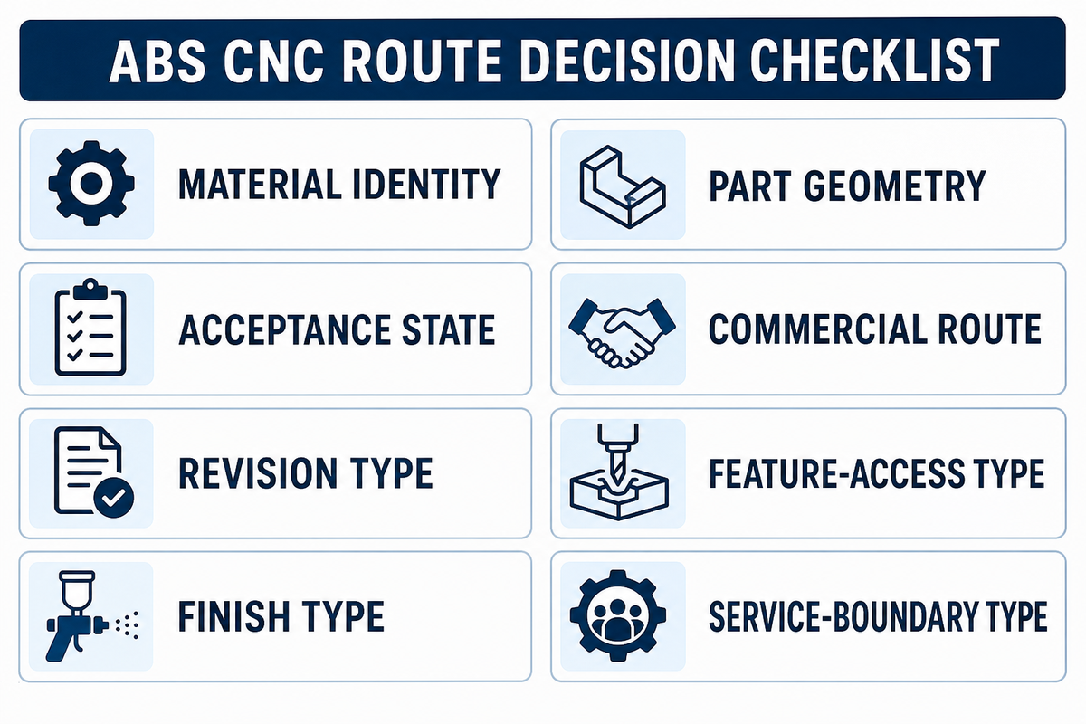
ABS CNC machining can be a sensible route for prototypes, fixtures, functional enclosures, and other custom ABS parts when a subtractive route gives the required geometry, surface access, and delivery logic. The first question is not whether a computer numerical control machine can cut the shape. Instead, the question is whether the defined stock and process can produce a part that can also be accepted and measured in its intended state. Start with the material identity. ASTM D4673-16 and ISO 19062-1:2015 describe ABS classification or designation fields; they do not turn every grade, supplier form, or manufacturing history into the same machining input. Confirm the edition required by the drawing or customer before treating either record as a project requirement. One current supplier material page also lists multiple ABS variants and explicitly qualifies tolerances by size, manufacturer, brand, and grade. That is why the drawing should name the requested stock rather than relying on broad labels such as “machining ABS” or “ABS plastic machining.” For an early program, the same defined stock and acceptance inputs can support a rapid CNC prototyping review.
| Decision type | What to define | Why it changes the route |
|---|---|---|
| Material identity | Named grade, stock form, supplier requirement, color or additives if relevant | The ABS material family does not supply one universal machinability or tolerance promise. |
| Part geometry | Walls, pockets, ribs, corners, holes, cosmetic faces | Tool access and workholding can matter more than a nominal machine label. |
| Acceptance state | Critical dimensions, finish, measurement condition, records | A part cannot be called precise until the relevant measurement decision is defined. |
| Commercial route | Quantity, iteration frequency, tooling commitment, delivery context | CNC milling, CNC turning, 3D printing, and injection molding solve different constraints. |
| Revision type | Controlled model, drawing, and an explicit source of authority | An old geometry file can invalidate an otherwise sound machining plan. |
| Feature-access type | Tool entry, tool reach, holder clearance, and exit condition | A nominal feature can be difficult to cut or inspect when access is restricted. |
| Finish type | Cosmetic faces, allowed tool marks, edge condition, and named surface finishes | Finishing can change both the route and the point at which the final part is inspected. |
| Service-boundary type | Chemical contact, temperature, stress, duration, and acceptance condition | These inputs belong to material validation, not to a generic machining adjustment. |
Can ABS be machined using CNC?
Yes—ABS can be machined using CNC, but the useful answer is conditional. Teams still need to verify the stock, feature geometry, support strategy, cutting response, and inspection requirement for the actual part. “Easy to machine” is not an acceptance criterion for precision machined parts.
The ABS Melt-Risk Index: Heat, Chip Escape, and Part Support
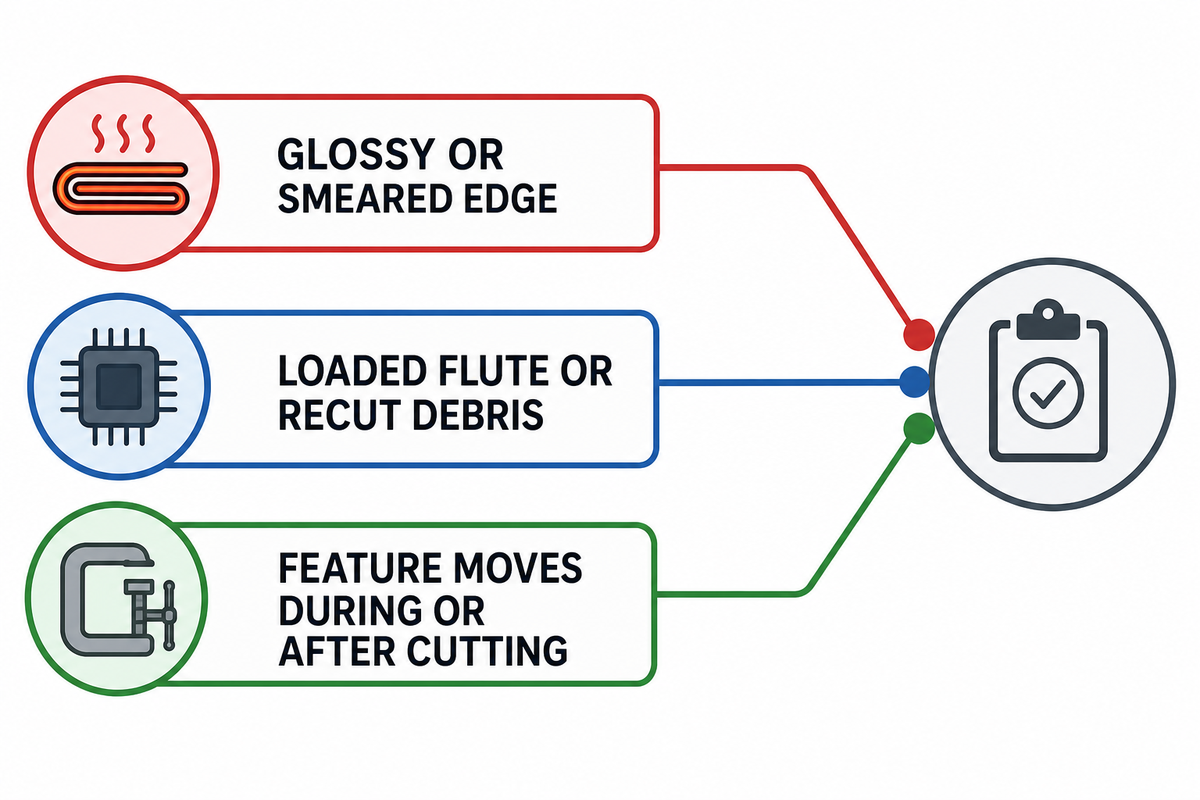
The ABS Melt-Risk Index is a controlled diagnostic heuristic, not a universal cutting chart. This index connects three observations: what is happening at the cutting contact, whether chips are leaving the cut cleanly, and whether the part stays supported while the tool passes. When an edge smears, a chip rewinds through a pocket, or a thin feature moves, the next action should be a single bounded test rather than a simultaneous change to every setting. Retained trade evidence supports a conservative machining boundary regarding thermal behavior and chip handling. It does not support a global spindle speed, coolant prescription or claim of every ABS sheet. Index use can establish what to observe first and then record the result on the named stock and setup.
| Observed signal | Index question | Controlled next test |
|---|---|---|
| Glossy or smeared edge | Is the cut removing material, or has the tool begun to rub? | Inspect tool condition, chip form, engagement, and one parameter change at a time. |
| Loaded flute or recut debris | Can the chip leave the feature before the next pass? | Review toolpath exit, pocket access, air or extraction arrangement, and chip observation. |
| Feature moves during or after cutting | Is the workpiece adequately supported through the cut and release? | Review clamp placement, remaining stock, cut sequence, and released-state measurement. |
Controlled-test rule: a visible symptom is a prompt to inspect the next variable, not evidence for a universal ABS process setting.
Tool Geometry and Toolpath Choices That Reduce Rubbing
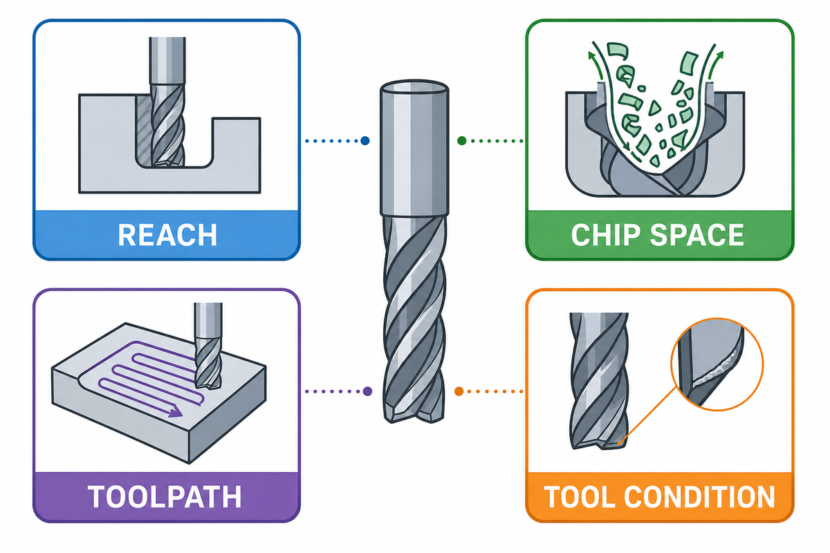
Tool geometry and toolpath choices should make the intended cut possible before a feed rate is debated. Sharp cutting edges, enough flute space for the observed chip, suitable reach, and a path that does not dwell need to be evaluated together. The point is not to copy a shop’s preferred end mill into another project; it is to prevent a thermoplastic surface from being treated as though rubbing were material removal. General tooling guidance from Bantam Tools states that too-small chip load can make a tool rub and dull, and that slower is not always better. That supports a limited principle: a lower speed alone is not a reliable correction. It is not an ABS-specific parameter prescription. Each trial record should identify the tool, condition, stock, workholding, path, observed chip, edge appearance, and measurement result.
- Reach: consider whether the cutter and holder are able to reach the wall or pocket without sacrificing practical rigidity.
- Chip space: verify whether the actual chip formation has a clear avenue out of the feature.
- Toolpath: use entry, exit, step-over, and finishing decisions that can be tested against surface quality rather than assumed from material name.
- Tool condition: if the symptom shifts after a change of tooling, it should be recorded as a process observation rather than accepted as proof of a universal ABS setting.
For complex geometries, ask the supplier to identify access and setup constraints separately from the evidence used to confirm dimensional accuracy. The relevant question remains whether the tool, holder, part support, datums, and inspection method all fit the specified feature.
Set Parameters by Reading the Chip and Part, Not a Universal Chart
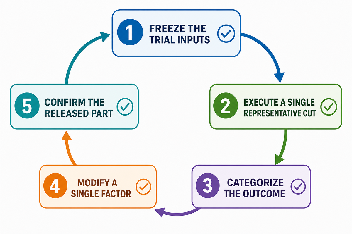
A responsible ABS machining process does not start with a copied chart and end with a claim that it is correct for every grade. It starts with a bounded baseline from the tool and stock information, a test feature that represents the real part, and one deliberate adjustment at a time. Operators then read both the chip and the part: chip shape, flute loading, surface quality, tool marks, burr condition, feature movement, and dimensions after the agreed stabilization period. This approach matters because a small chip load can shift the process toward rubbing; that is the specific counterexample to “just slow down.” It does not mean “always raise feed rate.” The safe conclusion is to control the test and keep the tool, workpiece, and setup visible in the record.
- Freeze the trial inputs. Record grade, stock form, cutter, tool condition, workholding, and feature.
- Execute a single representative cut. Incorporate a surface, wall or pocket that introduces the potential for the decision.
- Categorize the outcome. Log chip performance, edge condition, burrs, surface quality and measurement state.
- Modify a single factor. Record and implement one change at a time rather than large changes in spindle speed, feed rate, depth or work support.
- Confirm the released part. Measure after the agreed part state, not only while the workpiece is clamped.
Use this process for dry machining or another approved process route only within the actual shop’s controls. This guide is not a substitute for a Job Hazard Analysis, shop floor procedure or factory level control decision.
Workholding and Feature Design: Keep the Fixture From Printing Into the Part

This workholding review continues the recorded cutting response: a good-looking part can change when the clamp releases. Thin walls, long pockets, narrow ribs, unsupported holes, and cosmetic faces need a deliberate setup plan. Workpieces that are stable in one clamped orientation may not present the same dimensional state once they are released, turned, finished, or measured. Feature design should therefore expose the route question early. For an inside radius, record the radius, pocket depth, tool access, holder clearance, and chip evacuation route rather than reducing the problem to a single machine label. For a thin wall, record the intended support, cutting sequence, and released-state inspection. That retained trade-practice source is used only as requirements-led process context, not as a supplier-capability claim. These checks do not supply a universal limit; they identify where the design review needs a testable plan.
Ask for
- Datum and clamp locations before the first cut.
- Plan a sequence for thin or cosmetic features.
- Released-state inspection for critical geometry.
- Clear edge and surface-finish acceptance notes.
Do not assume
- Soft jaws alone prove a stable part.
- Fixture removal leaves the result unchanged.
- Generic tolerance covers feature relationship and part state.
- One successful prototype automatically proves production repeatability.
For an ABS prototype, the practical target is neither maximum clamp force nor minimum clamp force. It is enough support to make the cut repeatable while leaving a measurement route that represents the final part.
The 5-State Part Diagnostic Decoder
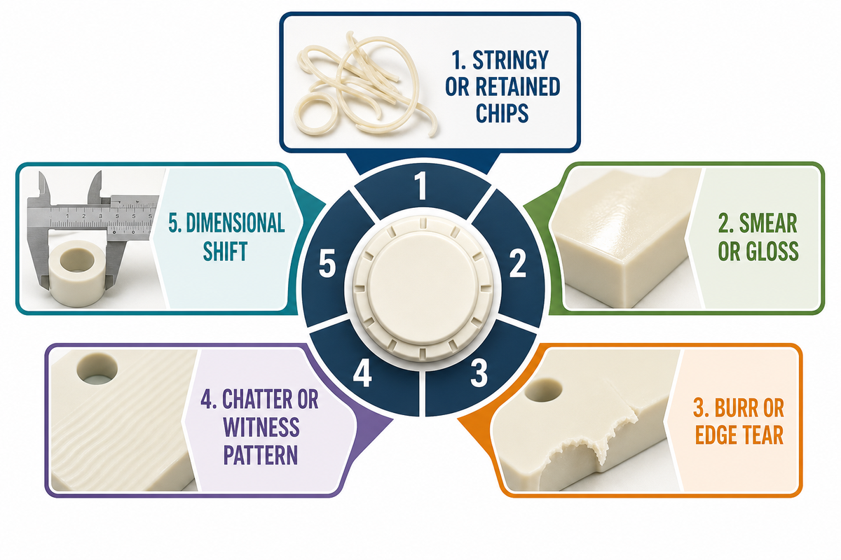
The 5-State Part Diagnostic Decoder then turns a visible symptom into a next check. This check follows the released-state review. It is not a fault dictionary and it does not diagnose every cause from appearance alone. Its value is that it prevents a team from treating distinct machining defects—stringy chips, smear, burrs, chatter marks, and dimensional shift—with one generic poor-surface-finish remedy; a poor result is not one defect.
| Part state | What to record | First controlled check | Do not conclude |
|---|---|---|---|
| 1. Stringy or retained chips | Chip route, flute condition, feature access | Review chip escape and toolpath before changing every cutting variable | That the material is defective from one chip form |
| 2. Smear or gloss | Tool condition, contact mark, chip evidence | Test for rubbing with one controlled adjustment | That one RPM value will prevent melting for all jobs |
| 3. Burr or edge tear | Feature exit, edge requirement, tool marks | Review edge direction, finishing pass, and deburr acceptance | That visual cleanup cannot affect the critical edge |
| 4. Chatter or witness pattern | Tool reach, support, clamp state, path | Check rigidity and support before declaring a material-only cause | That machine tools alone determine surface quality |
| 5. Dimensional shift | Clamped and released measurements, timing, datum method | Compare the agreed inspection state with the released part | That the initial clamped reading is the final part result |
In cases where the suspect cause may be related to exposure to other media like various chemical processes or environmental conditions, or other factors like residual stresses, then the decoder stops at the machining boundary and defers to material validation rather than suggesting a modification to the process.
ABS Versus PC, 3D Printing, and Injection Molding
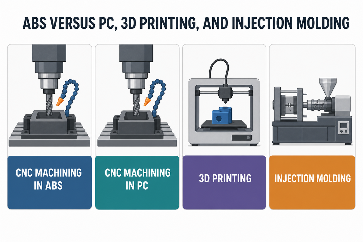
ABS versus polycarbonate, 3D printing, and injection molding is a requirements comparison, not a universal ranking. Start with geometry, mechanical properties needed in the actual service state, surface requirements, iteration rate, tooling commitment, quantity, inspection burden, and the availability of the named stock. Chemical resistance, impact resistance, tensile strength, heat resistance, and heat deflection are material-and-condition questions that need the applicable data sheet and validation plan—not generic values lifted from a search result.
| Route | Useful question | Boundary to preserve |
|---|---|---|
| CNC machining in ABS | Does subtractive stock give the required geometry, surface access, and test path? | The named grade and stock still require confirmation. |
| CNC machining in PC | Are the service requirements and fabrication behavior better served by the selected PC grade? | Do not claim compatibility or performance without material validation. |
| 3D printing | Does the geometry or iteration cycle favor a printed prototype? | Printed ABS findings do not automatically transfer to machined ABS stock. |
| Injection molding | Does a stable design justify tooling development and its validation work? | Do not use an unverified quantity crossover as a rule. |
The current supplier comparison page presents a numeric crossover range for 3D printing and CNC, but it does not establish an ABS-specific rule. This guide intentionally excludes that number. Manufacturing partners should explain the part-specific route assumptions before a process is selected.
Which is better for a CNC-machined part: ABS or PC?
Neither is automatically better. Compare the named grade, service environment, needed toughness or rigidity, appearance, geometry, machining response, and acceptance plan. Chemical contact and residual-stress conditions belong in material validation, not machining settings. Select the process from part-specific route assumptions rather than a generic crossover number. “Polycarbonate CNC machining” and “Acrylic CNC machining” name adjacent material routes, but they do not substitute for a grade-specific review.
Define the Inspection State Before You Promise a Tolerance
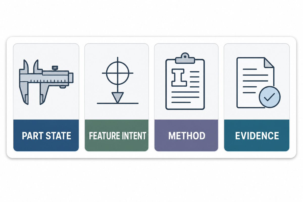
Tolerance promises are incomplete unless the team knows when and how the feature will be measured. Conditioning and measurement context can matter for dimensional stability. ISO 291 addresses standard atmospheres for conditioning and testing plastics; it is not a generic ABS machining-tolerance guarantee. NIST’s metrology material likewise supports traceability thinking, not a declaration that a particular part is fit for its application. Write the acceptance plan in a way that a supplier and buyer can use on the same part: the controlled revision, critical features, datums, applicable part condition, measurement method, sample or reporting expectation, and decision rule. If a dimension is evaluated after unclamping, after a wait time, or after a secondary process, say so. If a cosmetic surface is bead blasted, protected, or left as-machined, identify the relevant surface finishes and inspection point.
| Inspection field | Question to answer |
|---|---|
| Part state | Clamped, released, conditioned, post-finish, or another named state? |
| Feature intent | Which relationship is function-critical, and which dimensions are reference only? |
| Method | What datum scheme and measurement method will support the decision? |
| Evidence | What report, sample, or record is needed for this order? |
That discipline avoids the familiar failure mode where a team specifies tight tolerances but has not agreed on the part state that makes the number meaningful.
A Better ABS CNC RFQ: The 6-Field Handoff
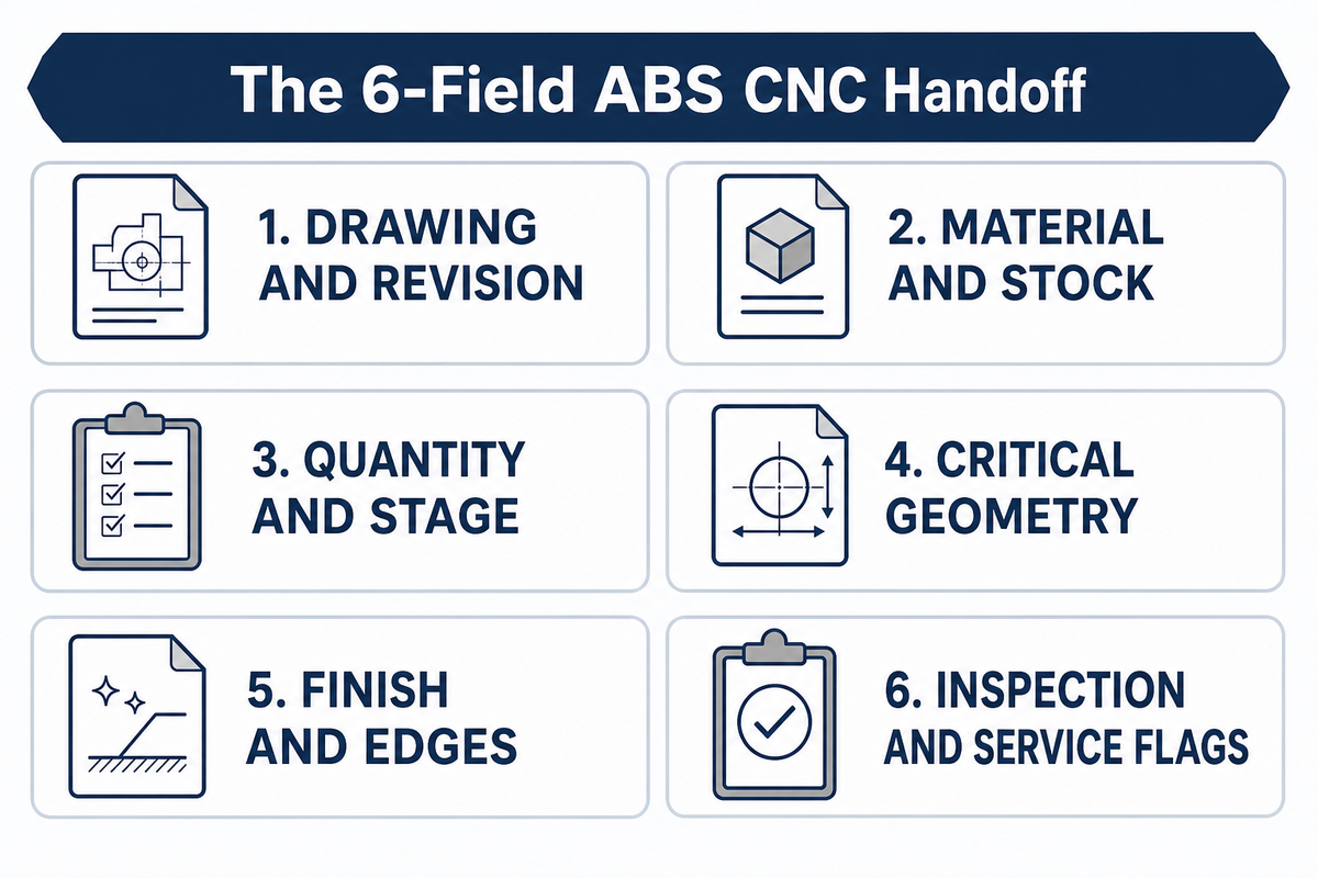
The 6-Field ABS CNC Handoff therefore functions as an RFQ readiness checklist, not a claim that a supplier has already accepted the work. This checklist makes the material, geometry, quantity, finish, inspection, and service boundary visible before quotation review. This produces a clearer technical conversation and a cleaner separation between this educational guide and a commercial service request.
| Field | Minimum handoff detail |
|---|---|
| 1. Drawing and revision | Controlled 2D/3D package, revision, datums, critical features, unresolved questions. |
| 2. Material and stock | Named ABS grade, form such as ABS sheets, required color or condition, permitted substitutions. |
| 3. Quantity and stage | Prototype, validation lot, or production context; expected order cadence if known. |
| 4. Critical geometry | Walls, pockets, threads, holes, cosmetic faces, tight tolerances, datum relationships. |
| 5. Finish and edges | As-machined or named finish, allowed tool marks, edge-break and burr expectations. |
| 6. Inspection and service flags | Measurement state, reports, packaging, and any chemical-contact or environment condition requiring material validation. |
When those fields are ready, a buyer can request a custom ABS CNC machining service review, or route a broader project through CNC machining service support. For an early iteration, the rapid CNC prototyping path can be discussed with the same controlled handoff.
What the Evidence Does, and Does Not, Establish
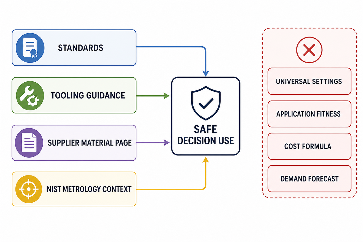
Each source in this guide has a narrow job. Material standards identify classification or designation fields. Material and machining sources frame questions for controlled trials. Inspection sources help define measurement context. None of them establishes one universal ABS cutting recipe, tolerance, cost, or service-performance promise. Use the evidence to decide what must be named, tested, measured, or escalated for the actual part. Where the next step is a commercial review, use the broader CNC machining service path with the controlled handoff rather than treating this guide as a quotation. Evidence-to-Decision Trace
| Source context | Safe decision use | What it does not establish |
|---|---|---|
| ASTM D4673-16 | Check classification or designation requirements in the drawing. | One machining recipe for every ABS stock form. |
| ISO 19062-1 | Keep the named material designation visible in the review. | No universal property set for every supplier grade. |
| Supplier material page | Name the grade, form, and tolerance context. | Part-specific service performance. |
| Bantam Tools guidance | Record chip and tool observations during a bounded trial. | No ABS-specific feed or speed setting. |
| Trade machining source | Use one-variable diagnostic checks for visible symptoms. | No global fixture, coolant, or thermal limit. |
| Hubs route comparison | Compare the actual part and iteration assumptions. | No ABS quantity crossover rule. |
| ISO 291 | Define conditioning and inspection context. | No machining-tolerance guarantee. |
| NIST metrology context | Define datum, method, and traceability expectations. | Fitness for a particular application. |
| Zhenling service page | Route a defined handoff to commercial review. | A capability claim made by this educational guide. |
How should broad machining terms be handled?
“CNC machined ABS,” “machining ABS plastic,” and “machining tips” are starting labels, not process instructions. Terms such as “carbide,” “5-axis,” “climb milling,” and “dry machining” still require tool, geometry, stock, setup, and shop-control verification. These cutting operations do not establish part-specific settings, and incorrect cutting parameters cannot be diagnosed from a label alone. Likewise, “cost-effective ABS” or “prototypes and end-use parts” describes a project context rather than a material property. Any request for excellent surface finish or dimensional accuracy should define inspection and acceptance. Thermal expansion, excellent impact strength, deflection temperature range, and low thermal conductivity must come from the named grade’s data and material-validation plan.
What are the downsides of ABS plastic for machined parts?
ABS machining downsides depend on the named stock, part geometry, and service condition; review thermal response, chip behavior, wall support, surface quality, edge condition, and inspection state.
For machining, review thermal response, chip behavior, wall support, surface quality, edge condition, inspection state, and the specific grade or stock form. Even a machined ABS part can look acceptable while its released-state measurement, cosmetic face, or burr requirement still needs work. For service, separately validate the actual chemical, temperature, load, duration, and residual-stress conditions. Generic “ABS is suitable” language cannot make those decisions or establish chemical compatibility.
Is ABS machining cost-effective?
Assess ABS machining cost-effectiveness by comparing quotations for the same controlled part definition, stock, quantity, finish, inspection state, and schedule; require each quotation to state its assumptions.
Treat the cost-effectiveness of ABS machining as a comparison exercise, not a universal formula. Ask each bidder to state which part definition, stock form, geometry, setup, inspection, finishing, quantity, packaging, and delivery assumptions are included. Compare quotations only when each bidder receives the same controlled drawing revision, named grade, surface requirement, quantity, packaging expectation, and acceptance plan. A low-cost statement without those common inputs is not a comparable basis for procurement.
What should be included in an ABS CNC machining quote request?
An ABS CNC machining quote request should include the 6-Field Handoff: the controlled drawing, named grade and stock form, quantity, critical features, finish, inspection state, and relevant service conditions before quotation review.
Include the controlled model and drawing, revision, named ABS grade and stock form, quantity and development stage, critical geometry and datum relationships, required surface finishes and edge condition, and the inspection state or report needed for acceptance. Identify which requirement controls when the drawing and model appear to disagree. Say whether an approved substitute is acceptable, whether color or appearance is functional, and whether a prototype result will be used to approve a later production route. Add service flags when the part may see chemicals, temperature, sustained load, UV exposure, cleaning media, or other conditions that could interact with material behavior. Those flags do not ask a machine shop to guess chemical compatibility; they make it possible to route the question to material validation before a misleading manufacturing promise enters the quotation. A useful quotation response should then state its assumptions, unresolved inputs, and the evidence it would need before confirming the final part.
References & Sources
- ASTM D4673-16 — ABS plastic classification and specification record.
- ISO 19062-1:2015 — ABS designation and specification fields.
- ISO 291:2008 — standard atmospheres for conditioning and testing plastics.
- NIST: Metrological Traceability — measurement and traceability context.
- Curbell Plastics: ABS — supplier-page grade and tolerance qualification, used with its stated scope.
- Bantam Tools: Speeds and Feeds Overview — general chip-load and rubbing caution; not an ABS parameter chart.
- Hubs: 3D Printing vs CNC Machining — process-comparison vocabulary; its non-ABS numeric threshold is not adopted.
- OSHA: Combustible Dust — facility-hazard referral only; not a safety conclusion for this article.
Research transparency: This guide uses standards, metrology context, and bounded supplier or tooling sources. It does not infer Zhenling capability, environmental safety, chemical compatibility, or a universal machining setting from those sources.
![Shop-Floor Carbon Steel CNC Machining Guide [2026]](https://zhenlingmetal.com/wp-content/uploads/2026/08/carbon-steel-cnc-machining-handbook-r2-featured-150x150.png)



ZHENLING / MADE-TO-PRINT MANUFACTURING
From Engineering Question to RFQ-Ready Drawing
Zhenling supports custom flanges, valve bodies, rolls, bent pipe, and profiled machined parts for industrial buyers. Our engineers review the drawing, material condition, tolerance stack, quantity, and inspection requirements before the machining route is quoted.
START WITHDrawing · Sample · Critical dimensions
DEFINEMaterial · Quantity · Tolerance · Certification
DRAWING / MATERIAL / TOLERANCE
Prepare Your Part Brief
- PART INPUT
- 2D/3D drawing or sample
- PROCESS REVIEW
- Machining · forming · welding · inspection
- RESPONSE ROUTE
- Submit the website inquiry form
We use your details to review and respond to the enquiry. See our Privacy Policy.


