Get in touch with Zhenling Company

By DD · Updated August 2026
CNC Machining vs 3D Printing is a route comparison with no universal winner. CNC machining often earns its place on accessible features, controlled interfaces, and repeat production from qualified stock, while 3D printing offers consolidated or enclosed geometry and low-commitment iteration. 3D printing and CNC machining produce parts through different manufacturing workflows; a hybrid route can print near-net geometry and machine the datums, bores, sealing faces, or interfaces. Decide which is best by the accepted part, not the machine cycle.
Zhenling’s public company information supports CNC drawing review and inspection only; it does not establish a 3D-printing capability. CNC machining and 3D printing are compared here as buyer routes, not as two Zhenling services.
CNC and 3D Printing Start with Opposite Material Flows
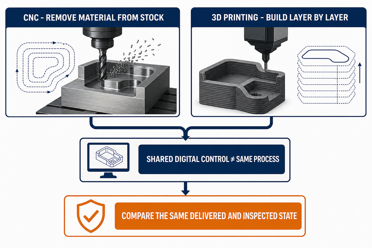
CNC machining cuts away material from a solid block or other stock form. Known as a subtractive process, CNC machining works by controlling cutting tools that expose the required geometry. 3D printing builds a part layer by layer from a 3D model and feedstock. Shared digital control does not make them the same manufacturing process.
3D printing technologies branch into materially different routes. An FDM 3D printer, resin-based machine, polymer powder-bed system, and metal 3D printing machine use different feedstocks, thermal histories, support strategies, hazards, secondary operations, and inspection methods. These 3D printing processes also create different 3D printing materials and material properties. CNC branches by turning, milling, grinding, electrical-discharge processes, machine configuration, workholding, and tool access. The official ISO/ASTM 52900 terminology record identifies additive process families; it does not promise tolerance, lead time, or price.
In a 3D printing vs CNC machining screen, part complexity and design freedom matter only after the route is named. The shorter phrase CNC vs 3D printing hides the same condition. 3D printing may create complex parts but leave critical surfaces unfinished, whereas a lathe may directly cut an accessible rotational form. Injection molding is a separate process, not a shortcut for either workflow.
Decision rule: compare the same released revision in the same delivered and inspected state. If one quote stops at “as printed” while the other includes finishing and acceptance evidence, the prices do not describe the same product.
The 9-Row Support–Stock–Surface Bottleneck Map
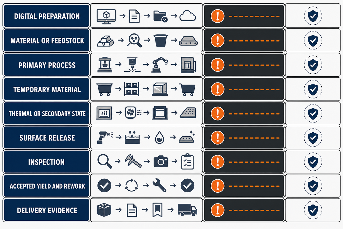
Machine time is only one row in a delivered-part route. The Support–Stock–Surface Bottleneck Map identifies the first unresolved dependency on each route. That row can control schedule, cost, or acceptance even when the primary machine is fast.
| Bottleneck type | CNC route | 3D-print route | Buyer question | Risk owner | Limitation |
|---|---|---|---|---|---|
| Digital preparation | Toolpaths, setups, fixtures | Build orientation, supports, slicing | Which revision and assumptions are released? | Route planner | A valid file is not a qualified process |
| Material or feedstock | Stock form, condition, certificate | Powder, wire, filament, or resin condition | Is the material state available and traceable? | Material supplier | Family names do not prove equivalence |
| Primary process | Cut accessible geometry | Build selected geometry | What state leaves the machine? | Machine supplier | Cycle completion is not part acceptance |
| Temporary material | Fixtures, tabs, or sacrificial stock | Supports, trapped feedstock, build plate | How is temporary material removed? | Process supplier | Removal may alter the surface or datum |
| Thermal or secondary state | Stress relief or coating when specified | Cure, sinter, heat treatment, infiltration | Which operations are required before measurement? | Qualified processor | A generic sequence may not transfer |
| Surface release | Finish cut, grind, polish, coat | Support cleanup, blast, machine, polish | Which surfaces contact, seal, slide, or locate? | Finishing owner | Appearance does not prove function |
| Inspection | Accessible feature and datum plan | External and internal inspection plan | Can every critical characteristic be detected? | Inspection owner | A written rule cannot make a feature measurable |
| Accepted yield and rework | Released setups and rework route | Build disposition and rework route | Which denominator defines accepted cost? | Quality owner | Produced quantity may differ from accepted quantity |
| Delivery evidence | Material and inspection records | Build, material, post-process, inspection records | What record travels with each lot? | Contract owner | Missing lineage can block release |
Use the map from top to bottom. Mark “defined,” “supplier to confirm,” or “unresolved” for each row. The first unresolved row is the current bottleneck. A buyer who finds unavailable qualified stock on the CNC route or an unproven internal inspection method on the additive route has learned more than a headline cycle-time comparison could reveal.
Compare Materials by Route, Condition, and Orientation
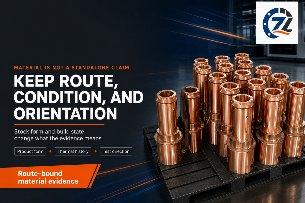
Material grade evidence cannot be separated from the route that created the test result. For a machined part, record the named material, product form, supplied condition, heat treatment, removal history, and test direction. For a printed part, record the 3D printing materials, 3D printing processes, build orientation, thermal history, post-processing, and test direction.
A peer-reviewed review of anisotropy in additively manufactured metals ties directional response to the material, build direction, thermal history, scan strategy, defects, and heat treatment. That evidence applies to the reviewed additive-metal scope; it does not rank a printed material against stock or establish a CNC material property. For machining, rely on the current stock certificate and product-form evidence rather than presuming isotropy.
The material-selection evidence checklist explains how to separate family, grade, product form, condition, certificate, and substitution rules before releasing a machining route. Add feedstock, build orientation, and post-process state when an additive candidate enters the comparison.
Let Geometry Decide Where Each Process Earns Its Keep
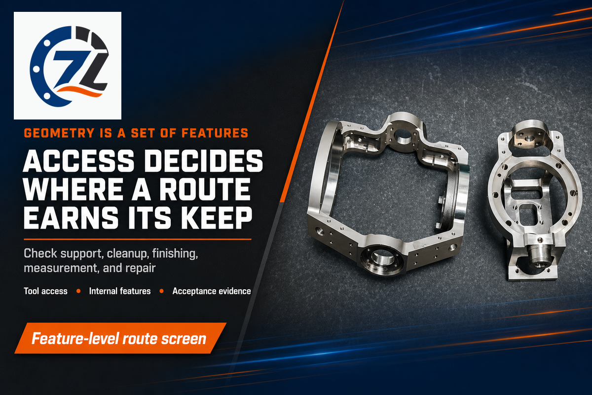
Geometry is not a process slogan. It is a set of features with access, support, release, finishing, and measurement needs. 3D printing may create enclosed channels, consolidated assemblies, or complex parts that are difficult to cut from a solid block. CNC offers a direct route to open faces, bores, threads, sealing surfaces, and datums that a tool and probe can reach. Machining provides that advantage only when access and workholding are controlled.
| Geometry condition | Possible route advantage | Disqualifying question | Acceptance evidence |
|---|---|---|---|
| Enclosed channel | Additive access without a conventional cutting path | Can feedstock, supports, finish, and internal condition be verified? | Qualified internal inspection and cleanliness rule |
| Consolidated assembly | Fewer separate components or joints | Does consolidation create an uninspectable or unrepairable region? | System requirement, inspection route, maintenance decision |
| Open bore or thread | Direct machining and gauging access | Is workholding stable and is the tool path accessible? | Feature, datum, tool state, gauge or method |
| Sealing or locating face | Controlled finishing from a declared datum | Will upstream operations leave enough stable allowance? | Surface definition, datum scheme, measured state |
| Large near-net form | Additive preform plus local machining may reduce stock removal | Can the preform be located, supported, and transferred reliably? | Allowance map, transfer datums, fixture and lineage record |
Do
- Split the CAD model into acceptance-critical features
- Test tool, support, cleanup, and inspection access
- Allow different routes for different features
Don’t
- Choose from overall shape complexity alone
- Treat consolidation as automatic system savings
- Approve an internal feature with no detection method
Tolerance and Surface Finish Need an Acceptance Plan
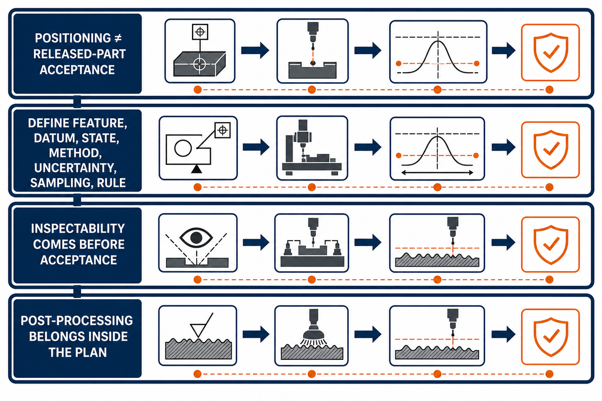
High precision, 3D printing accuracy, machine positioning, and released-part acceptance are not interchangeable claims. A useful tolerance statement names the feature, datum, material and process state, measurement method, uncertainty, sampling rule, and acceptance rule. A useful surface statement names the surface definition and the state in which it is measured.
NIST’s additive manufacturing measurement program identifies process variability, part accuracy, surface quality, material-property consistency, and qualification methods as continuing challenges. The separate NIST publication on inspection of embedded metal additive features explains why some internal geometry and defects are inaccessible to outside inspection and evaluates metrological X-ray computed tomography as a conditioned method, not a universal answer.
Inspectability comes before acceptance. An internal characteristic needs a detection method able to resolve it for the material, wall thickness, geometry, and uncertainty; a written limit alone does not make it measurable.
Post-processing belongs inside this plan. As Jessica Pompili writes in Additive Manufacturing Media, “Parts coming off a 3D printer often contain layer lines, excess powder, support witness marks and internal roughness.” The article’s surface-finishing overview is useful for routing questions, but any final method still depends on material, process, geometry, accessible surface, and acceptance definition.
For a machining-side treatment of drawing requirements, datums, measurement state, and near-limit decisions, use feature-level precision planning. Neither guide supplies a generic tolerance table because a number without its evidence envelope invites a false comparison.
Compare Cost per Accepted Part, Not Machine Price
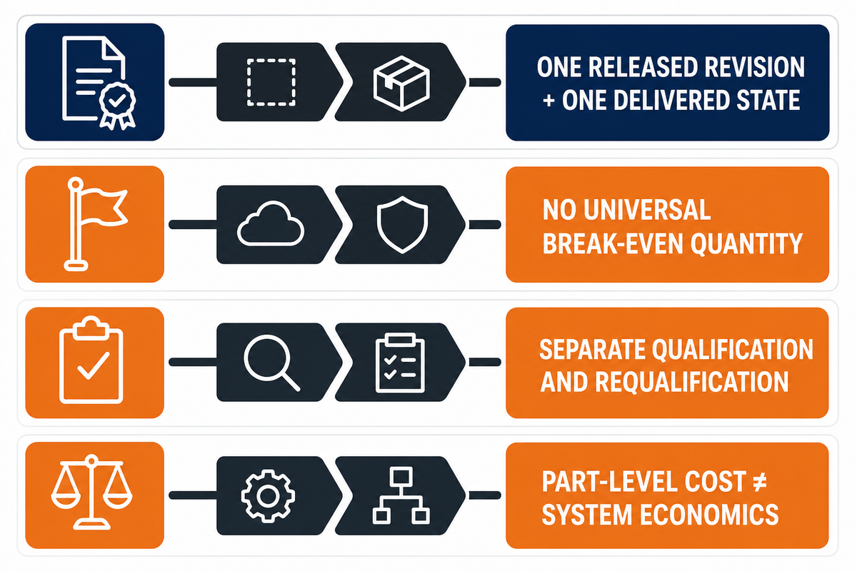
A fair cost comparison starts with one released revision and one delivered state. Normalize material, production volume, setup costs, processing, support or stock loss, secondary operations, finishing, inspection, accepted yield, rework, packaging, logistics, and buyer allowances. Part production at higher volumes is not automatically cost effective on either route; the cost comes from the whole accepted-part chain.
One review of additive manufacturing costs found that published models use different parts, machines, utilization, materials, and packing assumptions. The 2025 open-access activity-based study likewise makes laser powder-bed fusion cost depend on the process chain, part geometry, production rate, and post-processing. Neither source supports a universal quantity at which one route becomes cheaper.
For regulated or safety-critical use, separate non-recurring qualification, process-change control, and possible requalification from recurring accepted-part cost. NIST’s additive qualification program describes multiple qualification paths and requalification triggers. That makes qualification a decision boundary, not a hidden percentage to bury in machine time.
Keep part-level cost separate from system economics. Consolidation, inventory, transport, service stock, and disruption exposure are buyer inputs, not automatic savings. Using CNC machining may remove more stock; consolidation may make inspection or repair harder.
When the Best Answer Is Print, Then Machine
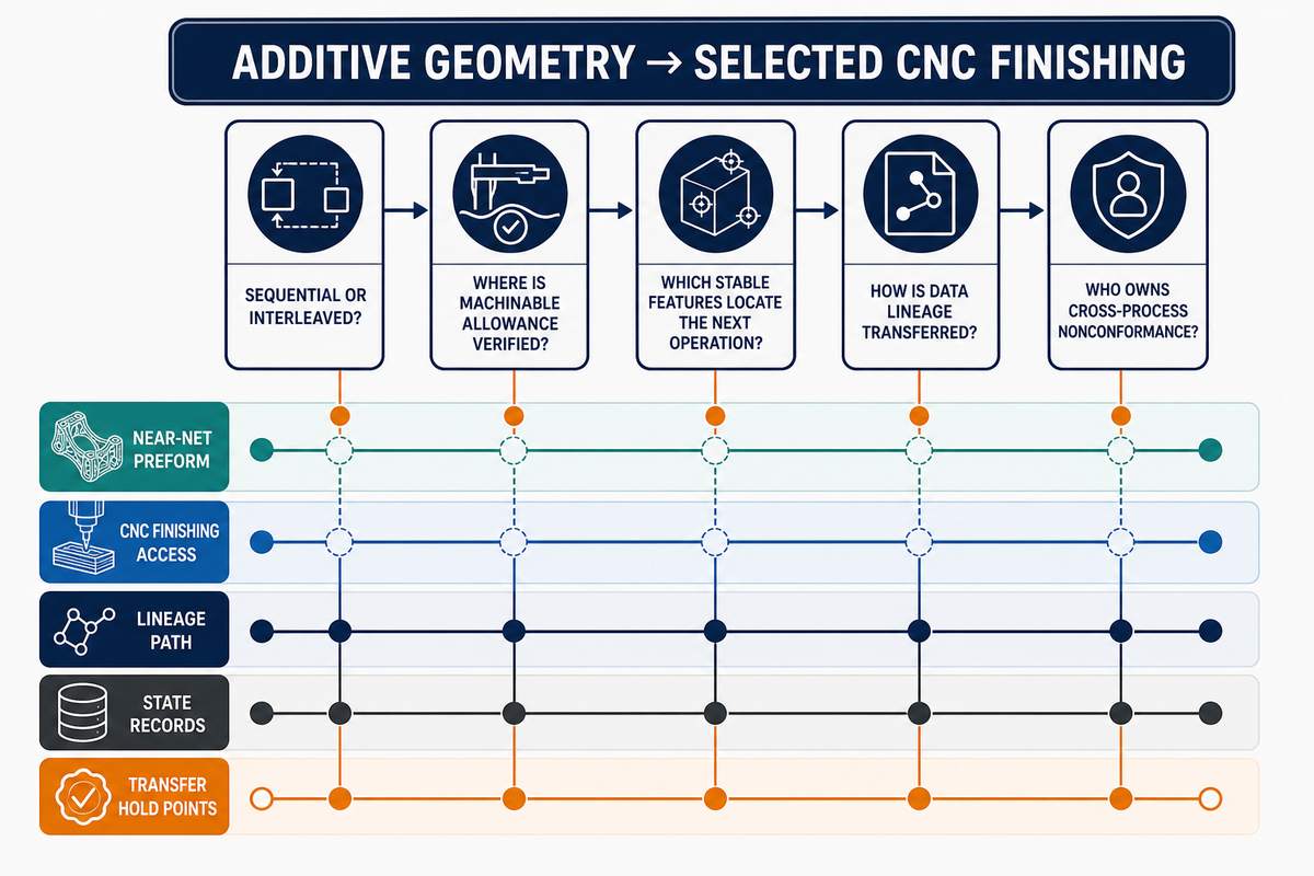
A hybrid route can use 3D printing where it creates valuable geometry or a near-net preform, then finish selected surfaces using CNC machining for tool access, datum control, contact, sealing, or direct measurement. An Oak Ridge National Laboratory metal additive case describes deposition, geometric analysis, and finish machining. It supports that conditioned sequence, not a universal productivity claim.
Hybrid does not always mean “finish the entire build, then transfer it once.” A peer-reviewed hybrid-manufacturing review distinguishes sequential routes from interleaved deposit-measure-machine cycles. Interleaving can preserve access to a feature that would later be enclosed, but it also makes operation timing, registration, contamination control, datum recovery, and process-state records more important.
| Field | Release question | Evidence owner |
|---|---|---|
| Revision | Which CAD, drawing, and route revision controls? | Buyer |
| Route topology and timing | Sequential transfer or interleaved deposition and cutting? | Route integrator |
| Build orientation | How is orientation recorded and transferred? | Additive supplier |
| Printed and thermal state | As-built, stress-relieved, heat-treated, or other declared state? | Additive and thermal processors |
| Sacrificial allowance | Where is machinable allowance defined and verified? | Joint route owner |
| Locating datums | Which stable features locate the next operation? | Machining planner |
| Critical surfaces | Which surfaces must remain accessible, protected, or finished? | Drawing owner |
| Fixture | How is an irregular preform supported without hiding distortion? | Machining supplier |
| Measurement and detection limit | Can the method resolve each released characteristic? | Inspection owner |
| Machine and process state | What state must remain controlled at release? | Each process supplier |
| Recurring capability | What continuing evidence supports repeat orders? | Quality owner |
| Data lineage | Can each result be tied to build, heat, machine, lot, and revision? | Route integrator |
| Nonconformance owner | Who investigates and dispositions a cross-process failure? | Contract owner |
The card travels with the work. Missing allowance, weak datums, or broken data lineage can block finishing and release. Zhenling’s public scope does not establish responsibility for additive supply or its upstream records.
Use Three Buyer Scenarios Instead of a Universal Winner
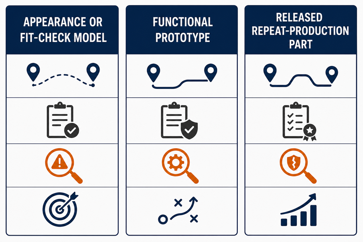
The same geometry can require a different route when its purpose changes. Prototyping and end-use parts do not need the same material evidence, dimensional proof, or change control. Plastic parts also need process-specific material and acceptance evidence. Zhenling’s rapid CNC prototyping scope is relevant only to the CNC route.
| Scenario | Possible route fit | Proof required | Hidden failure | Next buyer action |
|---|---|---|---|---|
| Appearance or fit-check model | Printing may support fast geometry iteration; simple machining may fit stock-like forms | Declared non-functional intent, envelope, interfaces, and finish expectation | Prototype appearance is mistaken for material or end-use approval | Freeze what the model is allowed to prove |
| Functional prototype | Choose the route that can represent named loads, interfaces, material state, and failure criteria | Material and route envelope, measurement plan, load case, and failure rule | A convenient substitute changes the mechanism being tested | List which production conditions must be represented |
| Released repeat-production part | CNC, additive, or hybrid only after route-specific evidence is controlled | Revision, qualification, lot records, sampling, change control, and accepted yield | A validated sample is treated as continuing process capability | Define recurring evidence and requalification triggers |
What to Send for a Route-Specific Quote
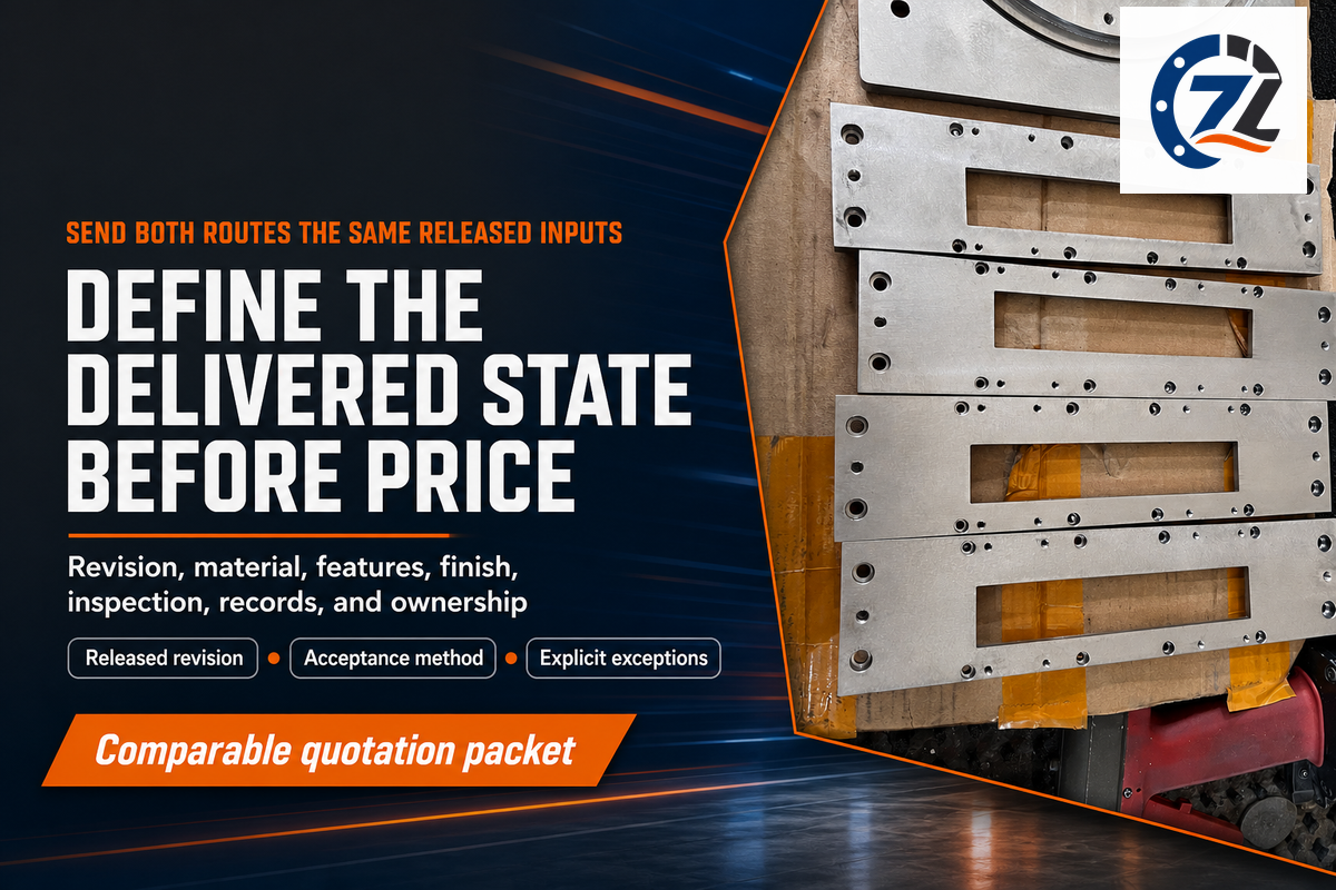
Send both suppliers the same released packet: drawing and CAD revision, material condition, quantity, critical features, final surface state, post-processing, inspection, certificate, delivery-lot, and alternate-route requirements. Include the delivered state, reporting scope, unresolved assumptions, and who owns each process handoff.
- Revision and intent: identify prototype, validation, or released production use.
- Material envelope: name the material, product or feedstock condition, certificates, and substitutions.
- Feature priorities: mark datums, interfaces, bores, threads, channels, sealing faces, and cosmetic zones.
- Delivered state: define support removal, thermal processing, machining, coating, cleaning, and packaging.
- Acceptance: state methods, sampling, reports, detection needs, and nonconformance route.
- For schedule and quantity, distinguish development pieces, qualification lots, and recurring lots.
This packet starts supplier review; it does not prove that a supplier can run, qualify, or inspect either route. Capability can change with machine, process state, feature access, material lot, quantity, and acceptance context. Ask for explicit exceptions and unresolved assumptions before treating the response as a comparable quote.
If a metal-powder route is being considered, ask the additive supplier, not Zhenling, to document facility controls for the named material and process. The current NIOSH additive-manufacturing guidance says hazards vary with the technology, materials, and environment. This is a facility-risk screen, not a performance ranking.
For the CNC side only, submit the packet for a CNC manufacturing review for your released drawing. That commercial page owns CNC capability and quotation intent; it does not represent an additive quote.
Frequently Asked Questions
Are 3D printers basically CNC machines?
Modern 3D printers use digital coordinates to add material, whereas CNC machining requires toolpaths that remove it; shared computer control does not make them the same process.
3D printing is known as additive manufacturing, while a CNC machine commonly removes material with cutting tools. Many 3D printers also differ by feedstock, support, thermal history, post-processing, and inspection route. Compare the delivered feature and evidence package rather than decide from the phrase “computer-controlled.” The route evidence still differs.
Is CNC harder than 3D printing?
CNC machining is often more demanding when workholding and tool access dominate, whereas 3D printing is generally harder when supports, thermal history, or cleanup control acceptance.
CNC machining generally adds programming, chip control, tool state, and setup-transfer decisions. Industrial 3D printing adds build orientation, feedstock handling, support removal, and post-processing. Either route can be simple for a concept model and difficult for a released part with critical dimensions, internal features, or material evidence. Acceptance defines the difficulty.
What is the biggest problem with 3D printing?
The key differences emerge after printing: supports, thermal processing, finishing, cleaning, and inspection may still control whether the delivered part can be accepted under its released specification.
A recurring procurement risk is treating the printed shape as the finished accepted part. Name the additive process, material, feature, and delivered state before deciding whether that risk applies. Internal-feature inspectability and supplier change control can become separate release problems. The printed shape alone cannot prove accepted state, process stability, or repeat capability.
Why would you add material and then remove it with CNC?
Use additive manufacturing for selected geometry, then machine the controlled interfaces; CNC machining delivers the datum, bore, sealing face, or contact surface required for release.
A hybrid route can build a near-net form, internal passage, repair region, or consolidated geometry and then machine controlled features. The route works only when allowance, printed state, operation timing, fixturing, measurement, and data ownership are defined before release. The additive supplier preserves stable material, identifies locating features, and transfers build and thermal records. The machining supplier confirms tool access, support, datum recovery, and inspection. The buyer or route integrator assigns nonconformance decisions and keeps each result tied to the correct revision, material lot, build, thermal state, and machining operation.
Will 3D printing make CNC machining obsolete?
CNC machining remains useful wherever controlled interfaces, accessible datums, direct measurement, or established stock best suits the released part and its evidence requirements over time.
CNC is better suited only where the named feature and acceptance route support that conclusion. The phrase “CNC machining is better” is not a universal rule.
Choose by Accepted State, Not the Process Label
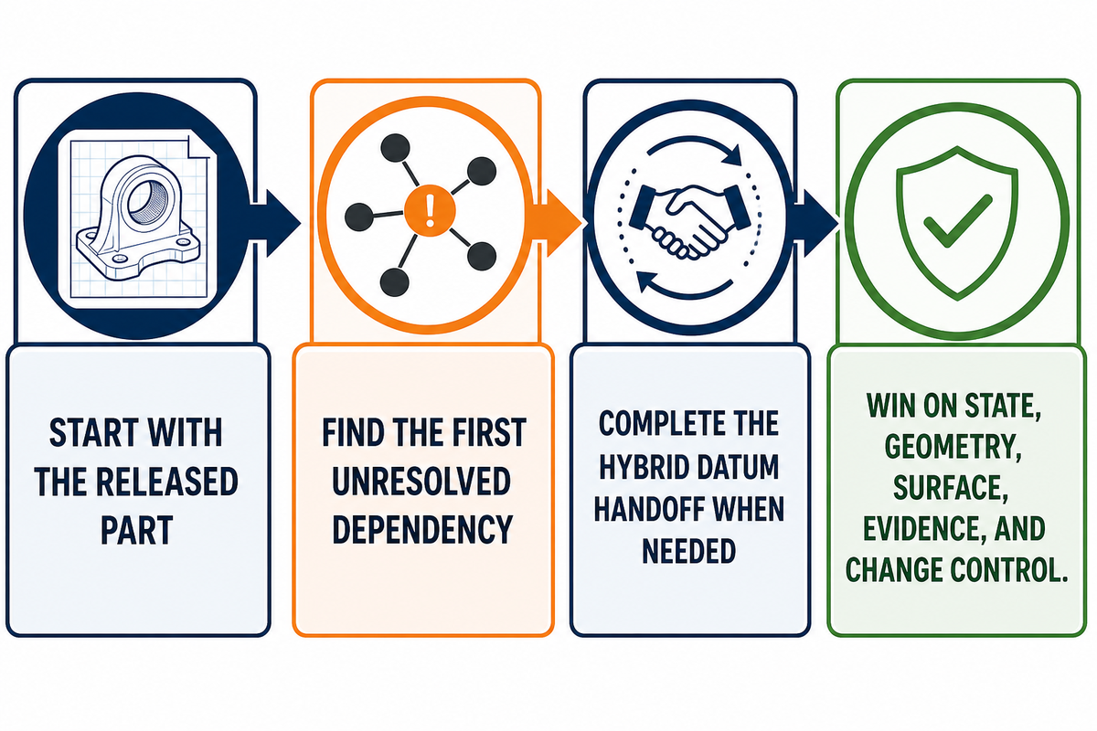
CNC machining versus 3D printing is not a contest between two machine brochures. Start with the released part, split it into acceptance-critical features, and use the Support–Stock–Surface Bottleneck Map to find the first unresolved dependency. If a hybrid route remains attractive, complete the Hybrid Datum Handoff Card before either supplier releases work.
The winning route delivers the required state, geometry, surface, evidence, and change control at an acceptable total cost and schedule. It may be CNC, additive, or a controlled combination.
How This Comparison Was Built
The comparison uses public NIST, NIOSH, ISO, laboratory, peer-reviewed, trade-press, and Zhenling sources. No private result, universal tolerance, break-even quantity, or additive capability was invented. Each claim is limited to its cited process, material, date, and specifically stated ownership context.
References & Sources
- ISO/ASTM 52900 additive manufacturing terminology International Organization for Standardization
- Additive manufacturing specification and tolerance considerations National Institute of Standards and Technology
- Measurement Science for the Additive Manufacturing Program National Institute of Standards and Technology
- Inspection of embedded internal features using metrological XCT National Institute of Standards and Technology
- Qualification of additive manufacturing materials, processes, and parts National Institute of Standards and Technology
- Large-format metal additive manufacturing and finish machining case Oak Ridge National Laboratory
- A review of additive manufacturing costs Peer-reviewed open-access literature
- Activity-based costing of laser powder-bed additive manufacturing npj Advanced Manufacturing
- Anisotropy in additively manufactured metals Peer-reviewed open-access literature
- Hybrid additive-subtractive manufacturing review Machines
- 3D Printing (Additive Manufacturing): hazards vary by technology, material, and environment National Institute for Occupational Safety and Health
- Surface finishing options for 3D-printed parts Additive Manufacturing Media