Get in touch with Zhenling Company

By CYH · Updated October 2026
Hard Anodizing Services convert the surface of aluminum to a hard anodic oxide coating for wear resistant applications. Precision components require specifications beyond a surface finish. Coating growth impacts the fit, sealing affects performance, and alloy chemistry affects the result. An aesthetically pleasing part may still bind during assembly.
Start with the surface that does the work. A sliding bore, an exposed housing, and a locating diameter can be made from the same aluminum alloy, but have different priorities. When making custom aluminum components, give anodizing companies the finished dimensional requirements as well as the name of the process. The following technical questions help guide inspection and rework decisions.
Hardcoat anodizing: what changes in the aluminum?
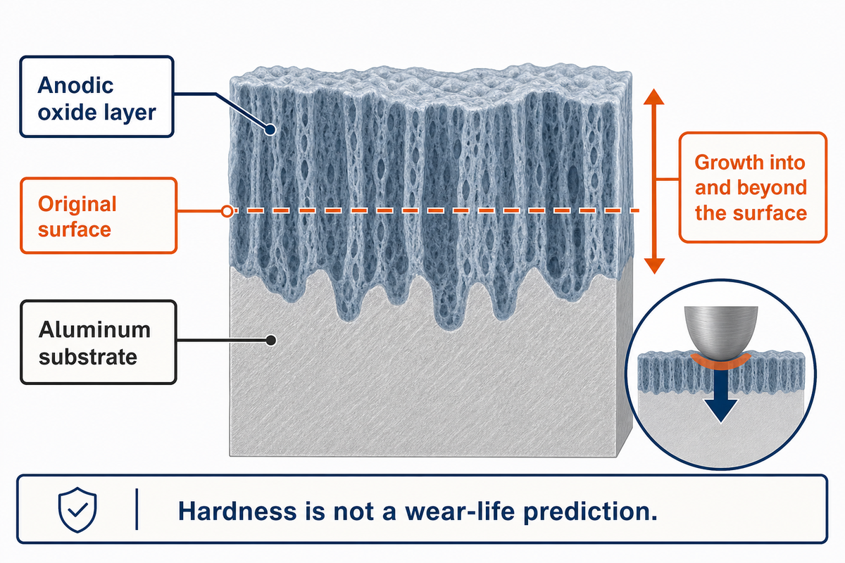
In hardcoat anodizing, electrical current converts a portion of the aluminum surface to an oxide layer through an electrolytic process. Type III anodizing favors wear resistance, and the alloy continues to carry the load. Coating continues to grow both into and beyond the original surface.
During sulfuric acid anodizing, formation and dissolution of aluminum oxide occur in an electrically conducting bath at a controlled temperature. The balance is affected by current density and alloy response. The layer of aluminum oxide is integrally bound to the substrate, and it isn’t a plating applied sheet. Its hardness comes with limited ductility; therefore, a soft substrate or a sharp loaded edge may allow surface damage.
“Hardness can be compared to wear resistance only under like conditions.”
That distinction is important when a drawing requires hard anodize but the failure occurs under a concentrated contact load. A hardness reading describes a specific test. It doesn’t predict how a coated edge would behave when subjected to repeated impact. For demanding applications, define the contact geometry and wear mechanism and then choose an acceptance test. Reliable anodizing begins with the definition of the working surface. Quality metal finishing requires inspection criteria for the same working surface.
A 50 µm film occupies only 0.05 mm through its thickness. It alters the working surface while leaving the load bearing aluminum underneath intact. Choose the alloy for structural loading, then select the hardcoat for the surface duty; treating the finish as a substitute for a stronger base material leaves the original load problem unresolved.
Aluminum alloys: why does the same finish behave differently?
Different alloying elements and the resulting difference in microstructure lead to different reactions of Aluminum alloys to oxidation, which explains differences in hardcoat results. Coating uniformity and appearance may also be influenced by other factors such as the presence of copper-rich areas, silicon particles, or casting porosity. Therefore, one has to look at the aluminum alloy and the appearance to discern if two materials meet a given nominal finish specification.
Practical differences between materials are discussed in the Aluminum Anodizers Council FAQ. The same cosmetic result shouldn’t be assumed for a wrought 6061 part and a silicon-rich casting when comparing aluminum alloys for machined parts. Even for high-quality aluminum stock, an alloy and condition need to be specified. Describing mixed metal parts only by their shared appearance leaves differences unresolved.
Why is color consistency so difficult to achieve in anodizing, especially across different batches?
Because of the nature of the alloy, surface texture and thickness of the oxide layer, colors in coated parts can vary. Adding dye does not necessarily remove these variances. Therefore, differences in color may be present between production lots, even if they all adhere to the same nominal color designation and coating specification.
For color matching, provide representative samples of the intended alloy and manufacturing route. Include the same pretreatment: bead blasting changes the surface texture and reflected light. Thick hardcoat may have a natural gray or brown shade that limits the aesthetic appeal of some dyes. Color anodizing and decorative finishes require a sample range especially if adjacent aluminum components will be seen together. Separate functional and aesthetic criteria for these aluminum parts. Industrial parts with a hidden wear surface may require a different appearance limit than a visible housing.
Two elements of a design specified at 50 µm can yield different anodizing colors, especially when the consistency of the alloy and the pretreatment isn’t kept the same. Agree on the level of contrast acceptable to the customer when both casting and wrought material are to be assembled in the same part.
Coating thickness: how much will the dimensions move?
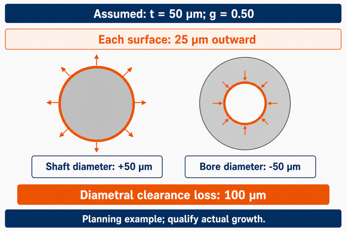
Coating thickness and dimensional growth are different quantities. Using an illustrative outward-growth fraction of 0.50, a 50 µm hardcoat moves each coated surface outward by 25 µm. A shaft gains 50 µm in diameter, a bore loses 50 µm, and coating both mating parts consumes 100 µm of diametral clearance.
About half penetration and half buildup are typical planning assumptions described in NASA’s PRC-5006 Rev D process specification. The document also notes that internal and external coating thicknesses don’t need to be the same and that a deep hole can receive less coating further from the opening. Measured process behavior is to be used for production compensation.
How does anodizing affect the dimensions of my part, and how can I account for it?
Anodizing increases external dimensions and reduces openings where coating grows above the original surface. Take into account each coated face that controls the measurement and add the effects of dimensional change of both mating parts. Indicate the dimensions after finishing. Thus machining allowance and coating inspection refer to the same geometric size.
Let t be total film thickness, and g be the outward growth fraction. One face moves by g × t. The diameter of a shaft increases by 2 × g × t. The diameter of a bore decreases by that amount. The diametral clearance loss of a coated shaft in a coated bore is (2gsts) + (2gbtb). Radial clearance loss is one-half of this value.
2-Surface Growth Ledger
The first eight rows use t = 50 µm and g = 0.50 on all coated surfaces. The unequal-film row uses separate inputs. These are a few geometry examples prior to any etching loss, final honing, roughness or taper.
| Feature or assembly | Outward-growth calculation | Dimensional effect |
|---|---|---|
| One coated flat face | 0.50 × 50 µm | Surface moves 25 µm outward |
| Plate coated on both faces | 2 × 25 µm | Thickness increases 50 µm |
| Coated shaft diameter | 2 × 25 µm | Diameter increases 50 µm |
| Coated bore diameter | 2 × 25 µm inward | Diameter decreases 50 µm |
| Slot with both walls coated | 25 µm + 25 µm inward | Width decreases 50 µm |
| Coated shaft, bare bore | 50 µm + 0 µm | Diametral clearance decreases 50 µm |
| Bare shaft, coated bore | 0 µm + 50 µm | Diametral clearance decreases 50 µm |
| Both mating parts coated equally | 50 µm + 50 µm | Diametral clearance decreases 100 µm |
| Both coated: shaft t = 40 µm; bore t = 30 µm; each g = 0.50 | 2 × 0.50 × 40 µm + 2 × 0.50 × 30 µm | Diametral clearance decreases 70 µm |
Consider a hypothetical guide assembly with a 20.000 mm shaft and a 20.120 mm bore before finishing. Initial diametral clearance is 0.120 mm. The engineer specifies 50 µm of coating on both parts and uses g = 0.50 for this planning exercise. The shaft becomes 20.050 mm; the bore becomes 20.070 mm. Remaining diametral clearance is only 0.020 mm, or 20 µm. If the design requires at least 40 µm, the assumed finish consumes 20 µm too much clearance. The next decision is to revise the prefinish dimensions or the coated surfaces, then qualify the actual process. Increasing the machining tolerance without controlling growth would leave the same assembly risk.
The half-growth approximation has limits. A 1955 thesis archived by the New Jersey Institute of Technology reported an average fraction of 0.41 for its Martin Hard Coat experiments. Applying 0.41 to two 50 µm films gives 82 µm of diametral clearance loss, compared with 100 µm at 0.50. That historical result demonstrates sensitivity; it isn’t a replacement setting for modern production.
For parts with tight tolerances, associate the finish allowance with precision machining prior to cutting metal. A predicted 20 µm clearance in the high-precision assembly leaves very little allowance for coating variation and bore taper. Threads need special treatment: this two-face calculation doesn’t take thread pitch diameter compensation into account.
Sealing: when does corrosion protection compete with wear?
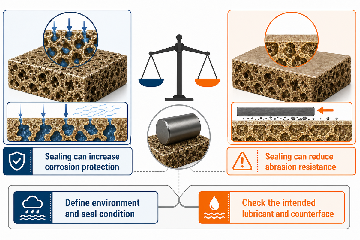
Sealing can close pores in the anodic coating, which can increase corrosion protection, but can also reduce abrasion resistance. Choose the seal condition around the working surface: if an exposed housing is sealed, the sealing prioritizes environmental protection. For a rubbing surface, a defined wear requirement and a suitable counterface need to be considered.
The Aluminum Anodizers Council reference guide distinguishes extreme abrasion service from sealing applications. Recommending sealing of every part overlooks that trade-off. Conversely, leaving every hardcoat unsealed can underestimate the environment that the finished assembly must withstand. Determine the environment that dictates a corrosion-resistant finish before specifying the sealing condition.
PTFE treatments provide another surface-function choice. In discussing anodizing solutions, lubrication, sealing and dye retention are considered different requirements. A treatment name doesn’t necessarily indicate the kind of roughness a sliding seal will encounter, or the kind of wear test an anodized aluminum component must pass.
In a hypothetical example, a designer is creating a 25 mm aluminum cylinder bore for a reciprocating polymer seal in a wet machine. In this first iteration, the designer is considering a 50 µm hardcoat because the bore will see repeated sliding. Exposure to water favors corrosion resistance. In either case, choosing the thickest available coating won’t resolve the concern, as sealing can influence abrasion. The designer provides the finish bore size and counterface texture, selects a sealing condition for the exposure, and checks the combination with the intended lubricant and seal. Honing allowances, if any, will be in the original dimensions, so the finishing operation doesn’t remove the coating from the working surface.
A 50 µm coating on a 25 mm bore creates two linked choices: the final fit and the surface the seal touches. Awareness of these will help inform your sealing decision. Where the wear test assumes unsealed hardcoat, sealing changes shouldn’t be automatically treated as cosmetic.
Type II, Type III or plating: which function comes first?
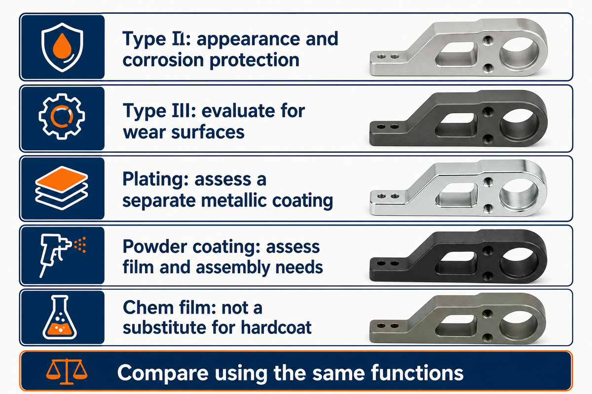
When appearance and corrosion protection are most important, pick Type II anodizing. For wear surfaces, evaluate Type III hardcoat anodizing. Metal plating deposits a separate metallic coating and thus needs an individual assessment. The choice needs to be function-first rather than a claim that one finish is best for every component.
Conventional anodizing provides more decorative flexibility. The broader family of the aluminum anodizing process includes clear anodizing and dyed finishes. When we say clear, it describes the appearance. It doesn’t mean that the buildup will be zero.
- Sliding or abrasive contact calls for evaluating hard coat anodizing with the alloy system under consideration, seal condition, and wear test.
- Visible color requirements invite a comparison of the Type II anodizing samples with the required shade and texture.
- A metallic surface needs to be analyzed separately for electroless nickel plating or a related specification of electroplate, including substrate preparation and final dimensions.
- Consider powder coating film and assembly requirements for decorative organic finishes.
- Chem film, or chemical conversion coating, is a separate case. A hardcoat requirement can’t be met by changing the finish name.
Coatings for aluminum should be compared using the same functions. Treat metal finishing solutions as separate process choices until their tests and dimensional effects are compared.
In a 2018 study by Kwolek and colleagues, cross-sectional hardness and Taber abrasion performance didn’t correlate for the 6061-T6 coatings tested. Their results from the constant-load scratch test did correlate to abrasion behavior. Hardness numbers, measured without specifying the test method, may mask differences between coatings.
The study examined coatings in the 19–43 µm range; those laboratory results aren’t a service-life prediction for a particular assembly. For comparison, maintain the test method and alloy constant. A wear loss result measured with one contact method cannot be ranked directly against a result measured with a different contact method.
Hardcoat defects: what does the symptom actually tell you?
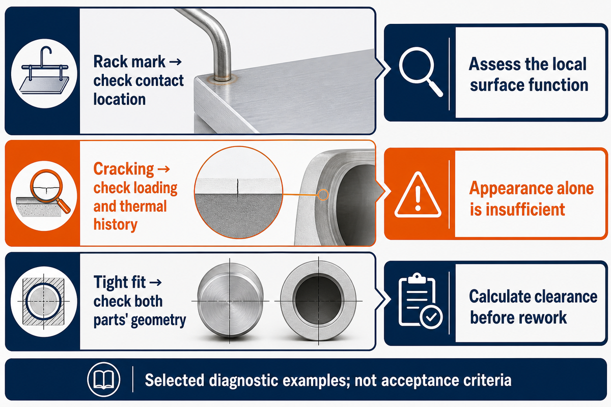
Hardcoat defects require different checks because a rack contact, burn, crack and tight fit arise from different mechanisms. Start with the symptom, location and function. Consider the finished dimensions and the coating condition to determine if the part needs further review or acceptance.
What are ‘racking marks’ and how do they impact my anodized parts?
Marks left by racking are the areas of contact where the part is held by the fixture and where electrical current is supplied during the anodizing process. Contact points can remain uncoated. The consequences of a contact mark left by racking on an agreed hidden area are different from a contact mark left on a sealing or locating area, or an exposed area.
NASA’s process guidance states that contact locations should be designated with respect to the part function. Clearly define acceptable rack locations prior to running, particularly when a drawing requires continuous coating. A request to mask a critical face also requires a boundary location. Neither of these should be open to interpretation when the machined parts arrive at the finishing line.
Hardcoat Failure Triage Map
This diagnostic map integrates NASA process guidance, the QUALANOD anodizing defect catalogue, and miscellaneous technical literature. QUALANOD addresses architectural anodizing; the mechanisms inform the queries and the bath recipes aren’t transferred to Type III processing.
| Defect type or symptom | Possible mechanism | First check | Decision consequence |
|---|---|---|---|
| Isolated rack mark | Electrical fixture contact | Agreed contact location and coating boundary | Assess the local surface function |
| Burn near an edge or contact | Localized current or heat concentration | Rack contact, agitation and process record | Investigate coating damage before acceptance |
| Fine cracks or crazing | Thermal mismatch or mechanical strain | Location, thermal history and applied loading | Assess function; appearance alone is insufficient |
| Rough sliding surface | Starting texture or coating topography | Measured final texture and counterface needs | Review finishing allowance and contact behavior |
| Batch-to-batch shade difference | Alloy, pretreatment, thickness or dye variation | Material records and approved sample range | Separate cosmetic limits from wear criteria |
| Patchy or thin coating | Trapped gas or uneven local processing | Orientation, geometry and thickness locations | Inspect the affected zone, not only the flat face |
| Wear-through in service | Contact duty exceeds local coating performance | Load, lubricant, counterface and actual film | Reassess the working interface |
| Corrosion pits | Local coating weakness or environmental attack | Exposure, seal condition and pit distribution | Trace the cause before repeating the finish |
| Tight fit after finishing | Growth allowance or internal coverage mismatch | Prefinish and finished geometry on both parts | Calculate remaining clearance before rework |
Surface cracking on cyclically loaded components should also be evaluated. In Sadeler’s 2006 research abstract, it was noted that approximately 10 µm of hardcoat on 2014-T6 shortened fatigue life in the high-stress region, but improved life in the low-stress region when compared to T6 material. This result supports a load-specific assessment and not a general fatigue penalty.
An apparent sealing failure may occur elsewhere in the process. Poor abrasion results in Sheffield and Oh’s 2019 architectural anodizing experiment were attributed to anodizing conditions. This points to the need to evaluate the full process history prior to modifying the seal tank. Quality control procedures should maintain the affected location and process history in order for the evaluation to differentiate these process effects.
A fit that closes from 120 µm to 20 µm suggests a different sort of investigation from a visible rack mark. Measure the dimension and location first, and then consider the relevant surface finishing options. Changing the finish without identifying the failure mechanism can preserve the original issue.
Hard anodizing services cost: where does the batch risk sit?
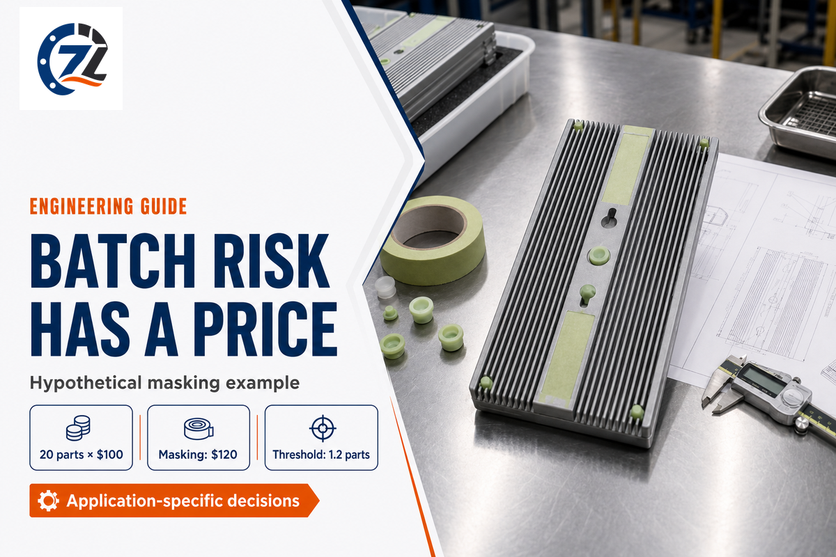
Hard anodizing services cost includes more than the finishing cost when a batch contains valuable machined parts. Masking and agreed contact locations can minimize exposure to an unacceptable finish boundary. Assess that work against the value at risk, using actual quotations and part costs instead of a generic price per part.
For a hypothetical batch of 20 parts, assume each machined part costs $100 before finishing. An additional masking operation costs $120 for the batch. If two parts become unusable because a critical surface was coated incorrectly, their prefinish value alone is $200. The masking cost equals 1.2 parts at $100 each. That comparison shows the financial threshold; it does not forecast the rejection rate or demonstrate masking will be financially justified. A purchasing team can replace the assumed numbers with its own quote and expected exposure. For small production runs, include inspection and replacement lead times when deciding which surfaces need extra process planning.
Compare surface finishing services on the agreed masking and inspection scope. A large-volume order and a short run require the same clarity about which surfaces may be coated.
Stripping isn’t a free reset. In his 2016 guidance on the removal of Type III coatings, Chesterfield details the dimensional issue. Aluminum converted to oxide is not restored when stripping removes the oxide. Even a non-etching stripping route can leave insufficient material for the intended fit.
From technical requirements to finishing services
Consider the calculations in the guide as a finishing discussion and identify the alloy, the working surfaces, and dimensions following a coating. Distinguish between the process specification and the part-specific inspection evidence. Evaluate what requirements of a standard are applicable to a given part based on the agreed manufacturing scope.
The Defense Logistics Agency record lists MIL-PRF-8625F with Amendment 2, dated November 23, 2020. ISO 10074:2021 addresses hard anodic oxidation coatings; its public scope excludes plasma electrolytic oxidation. These references are not interchangeable certificates.
Industrial and commercial clients can do a similar kind of handoff: a drawing showing defined working surfaces and finished dimensions. For custom finishes, identify which requirement changes from the normal process scope.
For project-specific metal finishing services, take the drawing and the chosen surface functions to Zhenling’s Hard Anodizing Services page. Discuss the rest of the fit allowance and required inspection before releasing the batch.
Hard anodizing FAQs
What is anodizing and why is it important?
Anodizing converts aluminum’s outer surface into an oxide coating for a chosen surface function.
The benefit may be appearance, corrosion protection or resistance to a particular form of wear. For a machined component, the process also changes dimensions and surface texture. Select the finish alongside the alloy and the assembly fit, including areas that must remain uncoated. That planning connects the surface treatment to the part’s actual duty instead of treating it as the last cosmetic operation.
What types of anodizing do you offer?
Type II and Type III are distinct process choices to discuss for the component’s requirements.
Type II commonly addresses appearance and corrosion protection, while hardcoat targets wear-related surface duties. The appropriate choice follows the alloy, coating thickness and final dimensions. Zhenling’s service page provides the project discussion route for the requested finish and geometry. Agree on the manufacturing scope for the drawing before ordering; this guide’s comparison doesn’t promise that every process variant suits every part.
Which industries benefit from anodizing services?
Machinery, automotive and aerospace applications use anodizing for different aluminum surface duties.
The useful requirement belongs to the individual part. A visible housing may prioritize appearance, while a sliding component needs a defined counterface and wear criterion. Aluminum anodizing services for medical devices also require application-specific assessment rather than an assumption based on the industry name. Across commercial sectors, specify the duty of the metal products being finished. State the operating conditions and applicable drawing requirements so the inspection plan addresses the intended assembly.
Can anodized parts be colored?
Yes, many anodized finishes accept dye, although hardcoat’s natural shade can limit the result.
Agree on representative samples for the chosen alloy and pretreatment. A color name alone can’t define the acceptable variation between batches.
Does a thicker hardcoat always last longer?
No. Thickness is one part of the working surface’s performance.
Wear also responds to the alloy, load and counterface. A thicker coating consumes more dimensional allowance and can affect texture. For a sliding contact, choose the film around the final geometry and the applicable test method, then evaluate the finished contact with its intended lubricant. Increasing thickness without resolving a poorly supported edge or an unsuitable mating surface can leave the original failure mechanism in place.
Does hard anodizing make aluminum stronger?
Hard anodizing hardens the surface; structural strength still depends on the base alloy and geometry.
Keep surface hardness and fatigue behavior separate when assessing the component’s loads.
Can an out-of-tolerance hardcoat part be stripped and recoated?
Sometimes, if enough dimensional allowance remains for the complete rework route.
Measure the part before authorizing another cycle. Coating formation has consumed some aluminum, and stripping or subsequent preparation may remove more material. A bore or locating diameter near its limit may have no useful allowance left. Review the remaining geometry and intended coating thickness with the responsible engineering team. Recoating can restore a surface appearance without restoring the original fit, so final inspection must assess the functional dimensions as well.
Written by CYH for Zhenling. Calculated examples are identified in the text; cited research belongs to the named authors and organizations.
References & Sources
- Typical Hardness of Type III (Hardcoat) Anodized Coatings Larry Chesterfield, Products Finishing, 2015.
- Anodized Aluminum FAQ Aluminum Anodizers Council.
- Process Specification for the Anodizing of Aluminum Alloys, PRC-5006 Rev D NASA Johnson Space Center, 2020.
- Variation of Thickness of Hard Anodic Films Alphons Raymond O’Konski, 1955; New Jersey Institute of Technology archive.
- Anodizing Reference Guide Aluminum Anodizers Council.
- Tribological Properties of the Oxide Coatings Produced onto 6061-T6 Aluminum Alloy in the Hard Anodizing Process Kwolek and colleagues, 2018.
- Anodizing Defect Catalogue QUALANOD.
- Effect of a Commercial Hard Anodizing on the Fatigue Property of a 2014-T6 Aluminium Alloy R. Sadeler, 2006; public abstract.
- It’s Not Always the Seal Tank Nathan Sheffield and George Oh, Products Finishing, 2019.
- Stripping Type III Hard Anodic Coatings Larry Chesterfield, Products Finishing, 2016.
- MIL-PRF-8625 Document Details Defense Logistics Agency.
- ISO 10074:2021 International Organization for Standardization.