Get in touch with Zhenling Company

Updated August 2026
Copper CNC machining is the use of computer-controlled milling, turning, drilling, and related operations to make copper or copper-alloy parts. When CNC machining copper, the label does not define one process window. Grade, product form, temper, feature geometry, tool condition, support, fluid state, and the inspection method all change what a valid trial must prove.
This guide is for drawing owners, manufacturing engineers, and buyers who need to diagnose burrs, chip problems, distortion, or disputed inspection results. For verified company background and general made-to-print machining scope, see Zhenling’s About page. The method here applies condition-bound evidence boundaries; it does not provide a universal speed-and-feed table, a tolerance promise, or private production data. Its job is to show how to turn a vague “copper problem” into a condition-bound validation plan.
Working with copper starts by separating the search phrase from the controlled input. “Copper for CNC machining” is not a single CNC machining material, and copper is often supplied in states that behave differently after cutting. The drawing and material record—not a family label—must settle that identity.
What Does Copper CNC Machining Actually Define?
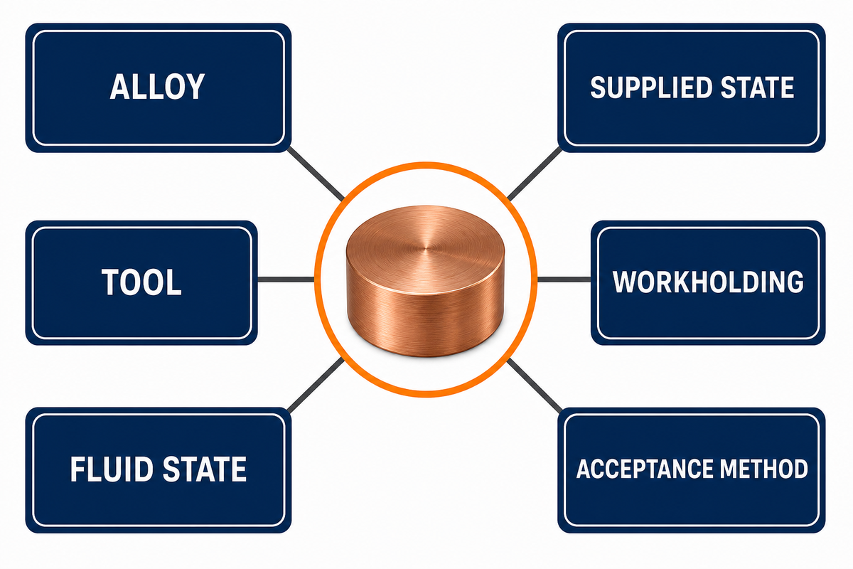
Copper CNC machining defines a controlled removal process applied to a named workpiece. It does not, by itself, define the alloy, supplied state, tool, workholding, coolant, acceptance method, or allowable substitution. Those fields must come from the drawing, material record, process plan, and inspection agreement.
That boundary matters because two parts described as “copper” can be designed around different functions. One may prioritize electrical conductivity and a contact interface; another may prioritize heat transfer, sealing, radio-frequency geometry, or electrode wear. The same visible burr can therefore carry different functional risk. Start with the requirement that can fail, then work backward to the evidence needed from the cut.
Start with Grade, Product Form and Temper—not Copper
A useful machining process begins with a controlled alloy designation, product form, and temper. Neither a family name nor a relative machinability rating is enough. It cannot authorize a material substitution, predict tool life, or become a cutting speed. Confirm what shorthand such as C110 or C101 means in the controlled material record.
Copper Development Association’s C11000 alloy record lists 99.90% minimum copper, 101% IACS conductivity at 68 °F, multiple form-and-temper entries, and a machinability rating of 20. Its C14500 record lists 93% IACS conductivity at 68 °F and a machinability rating of 85. These are named-source fields, not a fourfold productivity forecast.
Common search labels also cross different copper grades. Copper C110 may refer to C11000 electrolytic tough-pitch material, while labels such as C101 or “Copper 101” still require confirmation against the controlled designation. Oxygen-free copper, tellurium copper, and copper alloys containing nickel or tellurium are separate identities, not alternate names for raw copper. This guide does not authorize any substitution among them.
| Material evidence type | What it establishes | What it does not establish |
|---|---|---|
| Alloy designation | Controlled material identity | Approved substitute or cutting window |
| Product form | Plate, sheet, rod, tube, or other supplied form | Released-stress response of the finished geometry |
| Temper | Named supplied condition | Actual lot response under the selected cut |
| Relative rating | Comparison inside the source’s rating system | Speed, feed, finish, tolerance, or cycle time |
| Certificate | Required lot and chemistry record | Feature-level process capability |
| Critical feature | Where function can be lost | Cause of a future defect |
| Inspection state | Free, restrained, or assembled measurement condition | Service performance outside that state |
| Functional test | Named system or interface check | Proof for untested assemblies |
Before a trial, record the designation shown on the purchase order and certificate, the stock form, the temper, and any customer-controlled substitution rule. If one of those fields is missing, label the process proposal provisional rather than hiding the gap inside the word “copper.”
Translate Copper Properties into Cutting Behavior
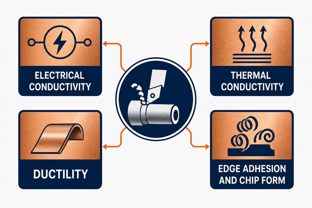
Electrical and thermal conductivity, ductility, adhesion, and chip form answer different questions when machining copper. High heat transport does not prevent material from adhering at the edge, smearing across a surface, or forming a long chip. Use a property table to generate test questions, not to claim that the material will be easy or difficult in every operation.
Material properties also need precise language. “Excellent conductivity” may describe a bulk value, while thermal and electrical conductivity are distinct measurements. Conductive does not mean immune to oxidation, and ductile does not mean every edge will deburr cleanly. Likewise, a corrosion-resistant requirement needs its own environment, surface state, and acceptance method.
“the benchmark values provided here can only offer broad guidance.”
That institute then calls for tests under actual production conditions. The same copper machining monograph describes long tubular or tangled chips as a pure-copper problem and discusses chip-breaking additions in particular alloy families.
That is a tradeoff, not a substitution instruction. An addition that changes chip behavior may also change conductivity, joining response, corrosion resistance, or a customer specification. Material selection must stay with the function and the drawing.
Do
- Separate heat transport from edge adhesion and chip form.
- Keep alloy, temper, tool, engagement, and fluid with each observation.
- Treat a published rating as a classification field.
Don’t
- Convert a rating into a speed multiplier.
- Infer contact performance from bulk conductivity alone.
- Change alloy to fix chips without design authority.
CNC Milling, Turning and Drilling Fail in Different Ways

That chip-and-alloy distinction makes operation-specific evidence more useful than a generic “gummy copper” diagnosis. CNC milling interrupts the cut and repeatedly re-enters the surface. Turning couples chip flow to a continuous edge and groove. Drilling confines the cut, chip, and fluid inside a hole. Surface finish, tool wear, and chip behavior must therefore be tied to the operation and to the location where the signal appears.
CNC turning records should identify the groove, edge, feed state, interruption, and evacuation path. Whether a file calls the output machined copper parts, copper machined parts, or turned parts, the label cannot replace the operation-specific record.
| Observed signal | Competing causes to separate | Separating observation | Next controlled check |
|---|---|---|---|
| Milled finish changes suddenly | Edge buildup, edge damage, recutting, support change | Inspect edge and chip while holding path and engagement constant | Repeat one short feature with a documented edge state |
| Turned chip packs or wraps | Chip geometry, feed state, groove, interruption, evacuation | Record chip form and evacuation path, not only spindle load | Change one chip-control variable inside supplier limits |
| Drilled exit burr grows | Edge state, feed near breakthrough, backing, runout, chip packing | Compare entry and exit, then inspect backing and edge | Test the breakthrough segment without changing every parameter |
| Thin wall shifts after release | Cutting force, fixture distortion, released stress, heat, datum change | Measure restrained and released states at a recorded temperature | Alter support or sequence before applying an offset |
One peer-reviewed T2 pure-copper milling experiment tested 200–1000 m/min, 0.1–0.3 mm/r feed, and 0.5–1.3 mm axial depth with a named machine and carbide insert. At one tested condition—600 m/min, 0.1 mm/r, and 0.5 mm depth—the paper reports Sa 1.80 μm and Sq 2.25 μm. Those values describe that experiment; they are not C11000 starting settings.
| Evidence field | Published value | Transfer boundary |
|---|---|---|
| Tested speed range | 200–1000 m/min | T2, named insert and machine |
| Tested feed range | 0.1–0.3 mm/r | Study feed definition only |
| Tested axial depth | 0.5–1.3 mm | Not a wall-thickness rule |
| Reported example | 600 m/min, 0.1 mm/r, 0.5 mm | One experimental condition |
| Measured response | Sa 1.80 μm; Sq 2.25 μm | Named surface measures, not functional acceptance |
Design Features around the Failure You Need to Prevent
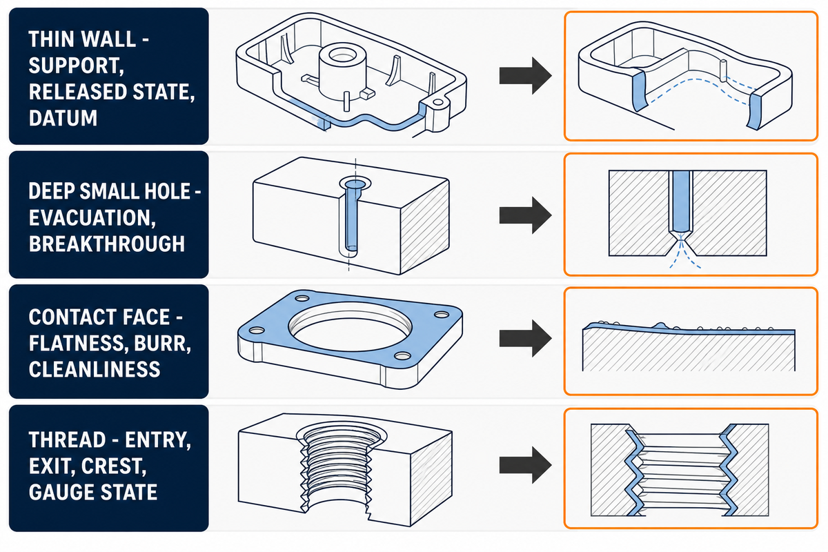
That operation-level evidence must be translated into feature design, with the likely failure and inspection method named. A thin wall raises support, released-state, and datum questions. A deep small hole raises chip evacuation and breakthrough questions. Contact faces raise flatness, burr, cleanliness, finish, coating, and assembled-resistance questions. Threads add entry, exit, crest, and gauge-state questions.
One public abstract on micro-milling copper thin walls reports smaller burrs and deformation under down-milling than up-milling with a 0.5 mm diamond-coated cutter. The full paper is paywalled, so this is a study-specific clue—not a rule that down-milling will protect every wall.
Workholding also belongs in the design conversation. The signed Cutting Tool Engineering article on challenging parts identifies geometry, material availability, geometric tolerancing, cutting forces, and fixture design as interacting variables. Its numeric examples are not copper data, but the decision boundary transfers: delicate features need a support and release plan before cutting begins.
For each high-risk feature, add four drawing-review questions: What function fails if the feature moves? In what state is it accepted? What support changes the measured result? Which burr, edge, cleanliness, or surface condition needs a stated limit?
Designing copper features therefore begins with function and measurement. Useful design considerations include access, support during cutting, released-state distortion, edge location, mating condition, and the inspection force that the feature can tolerate.
Build a Process Route without Copying a Universal Recipe
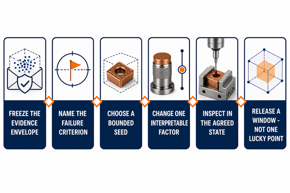
That feature-and-support review leads to a defensible route from material identity to a controlled trial, then from signals to one-variable checks. It does not begin by pasting a web table into a machine program.
- Freeze the evidence envelope. Record alloy, form, temper, lot requirement, feature, stock allowance, tool, edge state, holder, engagement, support, fluid state, machine, and measurement method.
- Name the failure criterion. Choose the burr location, chip behavior, surface measure, released dimension, tool signal, or interface condition that can reject the trial.
- Choose a bounded seed. Use a current tool-supplier recommendation, qualified shop history, or a published experiment only where its conditions match. Mark every mismatch.
- Run a production-representative coupon or feature. Hold the evidence fields stable and change one interpretable factor at a time.
- Inspect in the agreed state. Record temperature, time, restraint, datum realization, method, and uncertainty before accepting a correction.
- Release a window, not a single lucky point. Confirm that the chosen route remains acceptable across the planned tool-life and material-lot boundaries.
This route cannot prove a universal cause from a short sequence. Factor interactions may remain. Its value is narrower: it prevents a symptom, a setting, and a final dimension from being detached from the conditions that produced them.
A prototype can test the route, but it does not release production by itself. Put deburr, cleaning, coating, or electropolishing in the route only when the drawing and function require them, then inspect the state produced by that named step.
How Do You Make a Copper Trial Record Reusable?
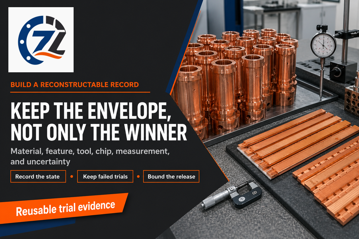
A reusable copper trial record lets another engineer reconstruct what was cut, what changed, what was measured, and what remains uncertain under the stated production and inspection conditions. The record should preserve the evidence envelope rather than only the “winning” setting.
Begin with material identity: designation, form, temper, lot or certificate requirement, stock size, and substitution status. Add the feature identity: drawing revision, feature and datum, nominal stock allowance, tool access, edge requirement, and whether the part is measured free, restrained, or assembled. Record the machine and setup only to the level needed to explain stiffness, reach, runout, support, and chip evacuation.
For the cut, capture tool maker and identifier, geometry, coating if applicable, edge state, holder, measured overhang, operation, direction, engagement, programmed and observed feed state, fluid delivery, and a chip or burr image. Controller values without tool diameter, effective engagement, or feature context are not reusable parameters.
For the result, retain the exact characteristic, unit, datum realization, instrument or method, workpiece and fixture temperature, time since cutting, restraint state, uncertainty where relevant, and the acceptance rule. Mark unexpected events such as recutting, packed chips, a changed insert, a fixture adjustment, or a pause before inspection. Those events can explain why a nominally repeated part is not a true repeat.
End with two statements: what the trial supports and what it does not. For example, it may support one feature, one alloy/temper, one tool family, and a defined inspection state. It does not automatically support another alloy, a deeper pocket, a thinner wall, a later tool-life state, or an assembled electrical result. This final boundary is what makes the record safe to reuse.
| Evidence field | Required entry | Release question |
|---|---|---|
| Workpiece identity | Designation, form, temper, lot, certificate, substitution status | What material state did the trial actually cover? |
| Feature identity | Drawing revision, feature, datum, stock allowance, edge rule | Which geometry and function were tested? |
| Support state | Fixture contact, restraint, access, release sequence | Could support or release change the result? |
| Tool state | Tool identifier, geometry, coating, edge condition, holder, overhang | Can the cutting edge and assembly be reconstructed? |
| Cut state | Operation, direction, engagement, programmed and observed feed, fluid delivery | Which bounded process condition produced the signal? |
| Observed signal | Chip, burr, surface, load, edge image, interruption | What changed before the acceptance result moved? |
| Measurement state | Characteristic, unit, datum realization, temperature, restraint, method, uncertainty | Was the agreed quantity measured in the agreed state? |
| Decision boundary | Supported scope, excluded scope, change trigger, reviewer | What may be reused, and what requires a new trial? |
Keep rejected trials as evidence too. Failed chip-control changes, burrs that move from entry to exit, or dimensions that change only after release can narrow the next question. Link each record to the drawing revision, program revision, tool record, material lot, and inspection file. If any of those inputs changes, issue a new trial revision instead of overwriting the old one. The reusable record is not a polished success story; it is an auditable sequence that lets a reviewer see which variables were held, which changed, and why the released process boundary is narrower than the full copper family.
When Should You Reject a Published Copper Recipe?
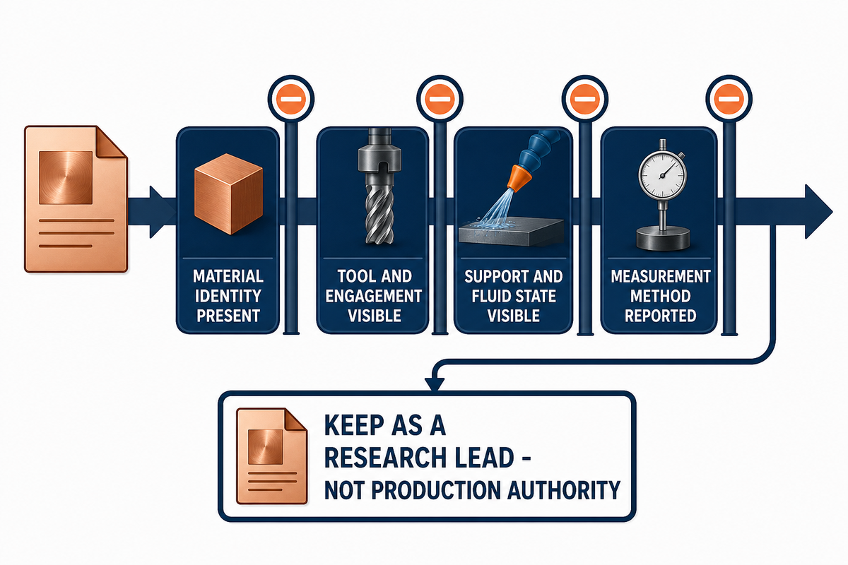
Reject a recipe as production authority when it omits the alloy or temper, mixes roughing and finishing, hides the tool or engagement, gives no support or coolant state, reports no measurement method, or presents one successful condition as a transferable window. You may still keep it as a research lead.
Also reject a direction claim when its scale changes. The thin-wall result above used micro-milling and a 0.5 mm cutter; it cannot decide a larger wall, a different tool, or another restraint. Reject a finish claim when it names only Ra while the function depends on burrs, waviness, flatness, contamination, coating adhesion, or contact resistance.
The strongest published number is often the one with the clearest boundary. Numbers without material, operation, tool, feature, and measurement context are weaker than a qualitative rule that tells you to test the actual production condition.
Inspect the Function, Not Only the Nominal Dimension

Acceptance begins by naming the measurand—the quantity intended to be measured—and the state in which it matters. Machine positioning accuracy is not finished-part tolerance. A released thin wall, a clamped inspection, and an assembled interface are different evidence states.
ASME’s Y14.5-2018 (R2024) catalog page describes the symbols, rules, definitions, requirements, defaults, and practices used to state and interpret geometric tolerancing. That scope does not make the standard automatic for every drawing. NIST’s measurement-uncertainty guidance explains why the measurand and uncertainty belong with the result.
| Question | Why it changes the result | Evidence to retain |
|---|---|---|
| What quantity is measured? | A size, form, location, roughness, burr, or resistance result answers a different question | Feature, characteristic, unit, and limit |
| What datum and restraint apply? | Soft or thin geometry can move under support | Datum realization, fixture, and free/restrained state |
| What temperature and time apply? | Thermal state and equilibration can change a dimensional result | Workpiece/fixture temperature, elapsed time, environment |
| How is uncertainty handled? | A result close to a limit needs a decision rule | Method, calibration status, uncertainty, and disposition rule |
NIST’s Engineering Metrology Toolbox identifies 20 °C as the industrial dimensional reference temperature and notes that thermal-expansion correction and coefficient uncertainty can enter the uncertainty budget. That does not supply a universal copper soak time. It tells the buyer and machinist to agree on temperature and equilibration instead of comparing unqualified readings.
Applications Change the Acceptance Question
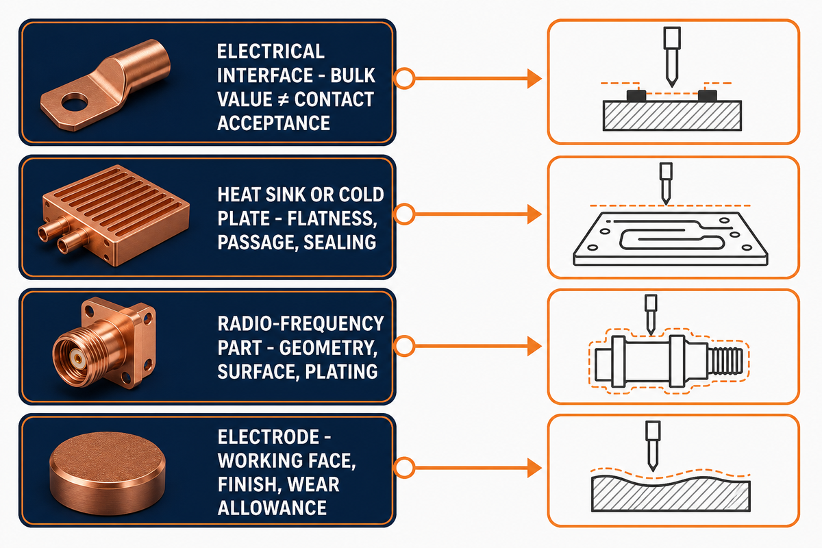
Application names should change the question set, not become performance proof. Busbars may require hole pattern, flatness, edge condition, coating, cleanliness, and an electrical test defined by the assembly. Heat sinks or cold plates may add interface flatness, passage integrity, sealing, and leak requirements. Radio-frequency parts may shift attention toward geometry, surface state, plating, and assembled response. Electrodes may prioritize working-face geometry, finish, and wear allowance.
Industrial applications of copper span more than electrical applications, and even an electrical conductor has several evidence layers. An RF component, a thermal interface, and a current-carrying joint can share an alloy family while requiring different geometric, surface, cleanliness, and assembled tests.
Bulk conductivity is material evidence, not finished-interface evidence. In the narrow electronic-relay context, the FDA’s relay inspection guide identifies film formation and surface contamination among mechanisms associated with contact failure and high resistance. That example does not govern every copper interface. It shows why the drawing owner must name the assembled function and surface state instead of relying on an alloy conductivity value.
Do not claim that a machined copper component proves the safety, cooling, radio-frequency, electrical, or wear performance of the finished system. Component acceptance and system validation are separate evidence layers.
Separate Copper Particulate, Metalworking-Fluid Aerosol and Beryllium Review
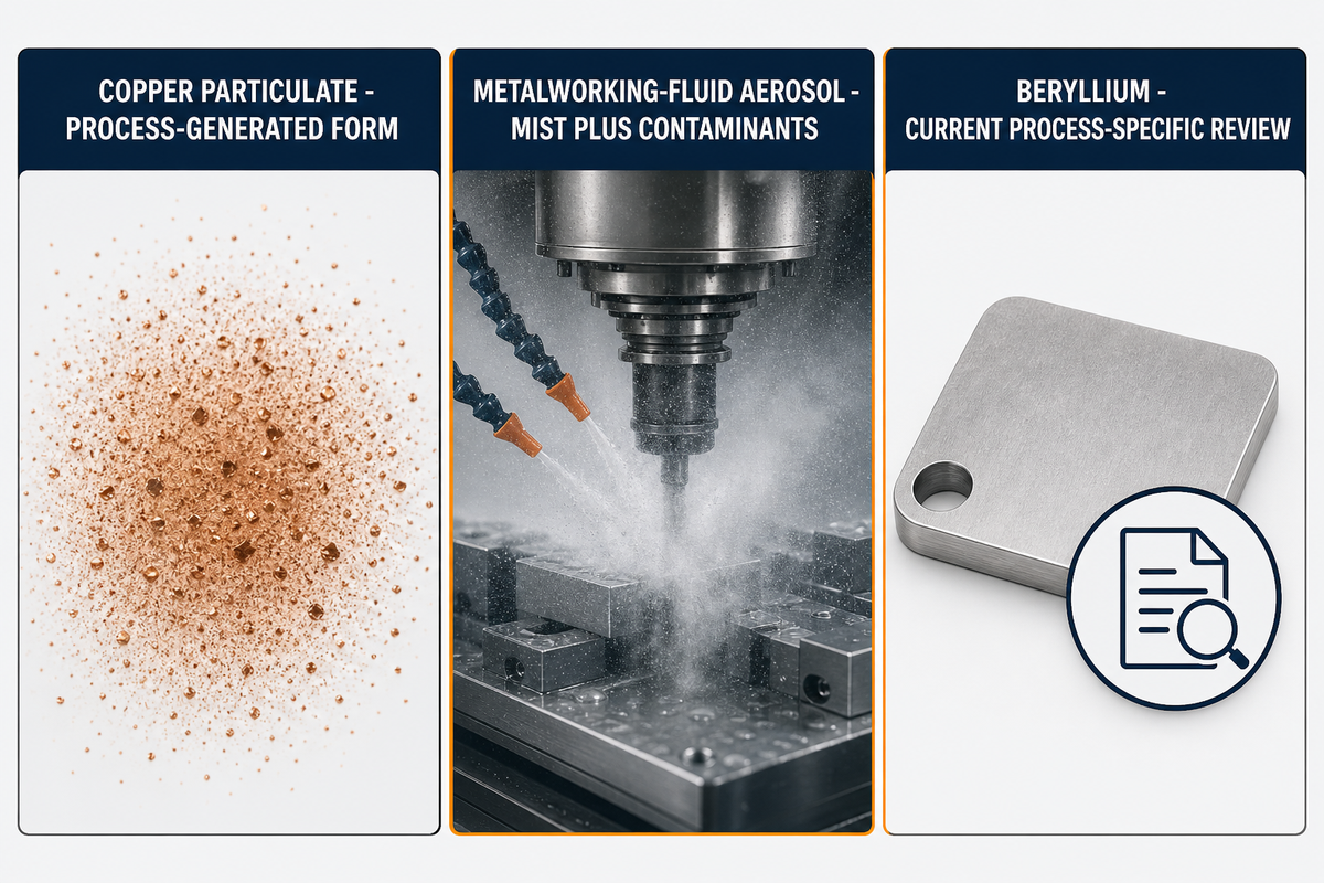
Occupational review must follow the process and material, not the finished part’s everyday handling. NIOSH’s copper dusts-and-mists page treats process-generated dust or mist as an exposure form. That does not mean bulk copper parts create the same exposure state.
The fluid system is another question. NIOSH defines metalworking-fluid aerosol as the mist plus contaminants, including fluid ingredients, process contamination, particulate, and biological products. It should not be reduced to “copper mist.”
The NIOSH pages are used here only to separate exposure forms; one is an archived topic page, and neither is a current, complete compliance checklist. Current obligations must be checked for the actual material, process, jurisdiction, and exposure evidence.
Beryllium-bearing materials require a current, process-specific compliance review. OSHA 1910.1024 includes scope conditions tied to processing, composition, and objective exposure data. An alloy label alone does not decide applicability. This article does not replace an employer’s exposure assessment, safety data, or legal review.
The 7-Layer Copper Machining Constraint Stack

The 7-Layer Copper Machining Constraint Stack is a minimum question set, not an exhaustive standard. Read it from the function toward the cut: application function → measurable acceptance characteristic → alloy/form/temper → feature and released state → operation/tool/engagement/support → chip/fluid/thermal state → inspection method and uncertainty.
A change high in the stack can invalidate decisions below it. If the alloy changes, do not keep the process window by default. If the wall or datum scheme changes, revisit workholding and measurement. If the interface function changes, revisit edge, surface, cleanliness, and test requirements. This prevents a local machining improvement from silently breaking the product requirement.
When those fields are ready, carry the alloy-to-acceptance record into copper project scoping on the existing solution page. It is also the proper place to evaluate a CNC machining service or compare copper CNC machining services against the drawing, material record, critical features, inspection state, and trial evidence; service configuration and quotation belong there rather than in this guide.
Discuss the drawing and validation plan
Frequently Asked Questions
Is C11000 easy to machine?
C11000 cannot be rated “easy” from conductivity alone.
Copper Development Association records list high conductivity and a relative machinability rating of 20, but neither field supplies settings. Define the product form, temper, operation, tool, edge state, engagement, feature, support, fluid delivery, chip criterion, and inspection state. Then judge the route with a controlled feature trial. A family label, conductivity value, or rating cannot predict burrs, chip control, tool life, finish, or released-part conformance by itself.
Can I use one speed-and-feed chart for every copper alloy?
No chart is production authority for every copper alloy and feature. It can only seed a condition-matched trial after alloy, feature, tooling, fluid, and measurement conditions are checked.
A chart may seed a trial only when its alloy, temper, tool, engagement, machine, support, fluid, and measurement conditions match. Record every mismatch. Run a production-representative feature, inspect the agreed failure criteria, and release a bounded window rather than one lucky point. The valid record should also state the tool-life and material-lot range checked. A relative machinability rating is not a speed multiplier, and a value reported for T2 pure copper is not automatically a C11000 or C14500 setting.
Does climb milling always reduce burrs on thin copper walls?
No universal climb-milling claim is supported.
One public abstract reports smaller burrs and deformation under down-milling in a micro-milling test with a 0.5 mm diamond-coated cutter. The full method is paywalled, and the finding stays inside that experimental context. Tool scale, wall geometry, alloy condition, support, runout, engagement, removal sequence, and inspection state can change the result. Treat direction as one controlled factor, not as a substitute for a feature-specific trial and released-state measurement.
Why can two inspectors disagree on a thin copper feature?
They may be measuring different physical or metrological states.
Compare the exact measurand, drawing revision, datum realization, support, free or restrained condition, contact force, workpiece and fixture temperature, equilibration time, method, calibration status, and uncertainty. Confirm that both readings refer to the same feature and unit. A machine-position value, a clamped in-process reading, and a released-part result are not automatically equivalent. If the readings sit close to a limit, apply the agreed decision rule before changing an offset. Repeat the measurement under one documented state, then change one state variable at a time. This separates a process shift from a measurement-state difference without assuming that either inspector is wrong.
When should copper machining move to a project review?
Move to project review when a missing condition can change the route or acceptance. Examples include alloy, feature support, edge condition, inspection state, and recipe context.
Examples include uncertain alloy or temper, a flexible critical feature, a functional burr or surface rule, an undefined inspection state, or a mismatched recipe. Bring the drawing revision, material record, quantity, critical features, mating context, failure signal, and acceptance method.
References and Source Boundaries
References & Sources
- Copper Development Association C11000 record — controlled identity, form/temper, conductivity, and relative rating.
- Copper Development Association C14500 record — named comparison only.
- German Copper Institute machining monograph — broad-guidance and production-test boundary.
- T2 pure-copper milling study — experiment envelope, not a recipe.
- Copper thin-wall micro-milling abstract — public abstract only; full text paywalled.
- ASME Y14.5 catalog scope and NIST measurement uncertainty — product-definition and metrology boundaries.
- NIOSH copper dusts and mists and NIOSH metalworking fluids — distinct occupational exposure questions.
- OSHA beryllium standard — current scope and conditional applicability; not legal advice.