Get in touch with Zhenling Company

Updated August 2026
5-Axis CNC Machining is the coordinated control of three linear directions and two rotary degrees of relative motion between the cutting tool and workpiece. Once a five-axis process has been selected, that label still does not prove that the posted program matches the machine, that the loaded work envelope is collision-free, or that the finished feature will conform. Release control must connect the machine model, post-processor, program, setup, and inspection record.
This guide begins after the process family has been selected.
It explains how to validate indexed and simultaneous motion on a named machine, control rotary-axis and synchronization error, qualify the post and simulation chain, and trace a released drawing to part evidence. It does not decide whether complex parts belong on 3-axis equipment, compare automotive cycle time, estimate single setup or setup time savings, compare routes with fewer axes, or normalize quotation cost. Here, all five axes have already been selected; the task is to prove the released machine-specific process.
What 5-Axis CNC Machining Actually Controls
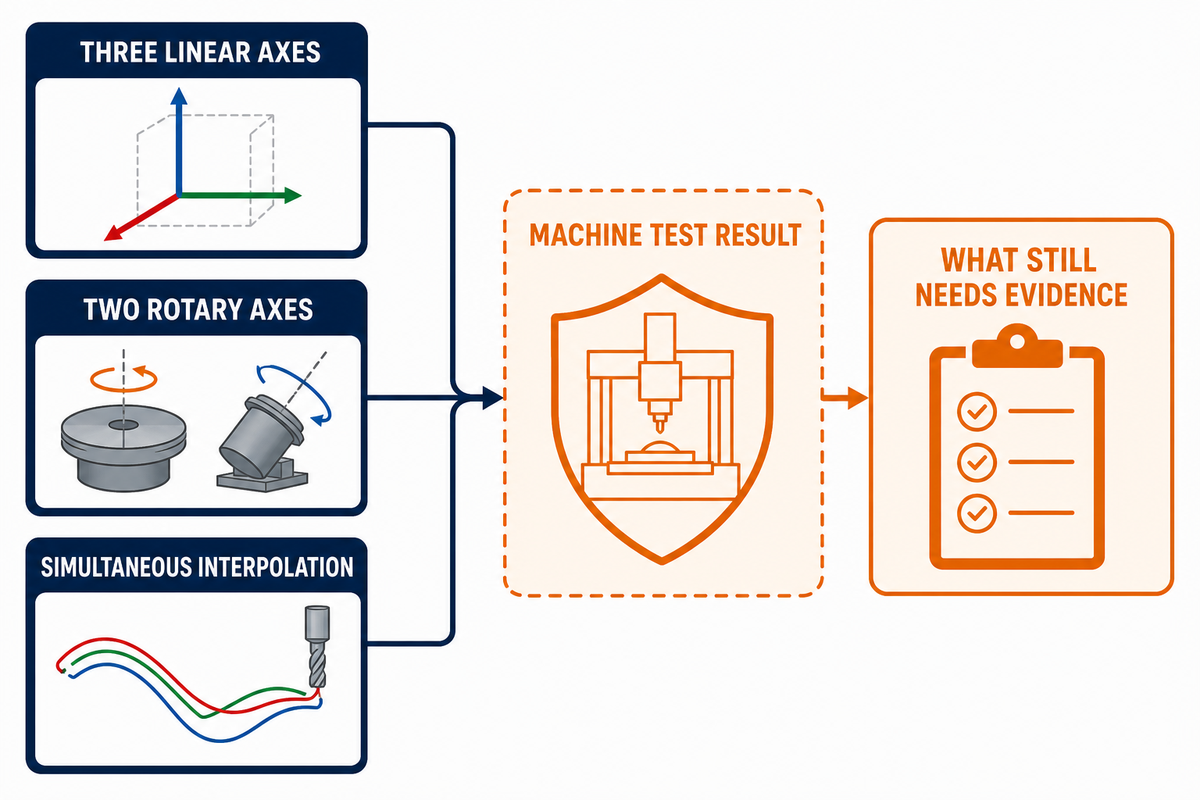
Five-axis describes coordinated relative motion, not one fixed machine shape. Three linear axes locate the cutting point in X, Y, and Z. Two rotary axes change the orientation between tool and workpiece. Those rotary axes may sit on the table, the head, or one on each side of the kinematic chain.
ISO 10791-6 applies to machining centres with three linear axes and one or two rotary axes, and it addresses the kinematic accuracy of simultaneous motion. That scope matters: a coordinated-motion test says something about the machine under defined conditions. It does not, by itself, prove that every feature on a buyer’s part will meet its drawing requirement.
NIST’s coordinated five-axis metrology work likewise treats kinematic models, test artifacts, and measurement methods as distinct pieces of machine-performance evidence. Buyers should therefore read “five-axis” as a motion capability that still needs a part-specific process plan.
Terminology varies. A five axis CNC machine, 5 axis CNC mill, or 5 axis milling machine may also be called a 5-axis machine. Marketing sometimes says these machines move tools along five different axes, or along five different axes simultaneously. Engineering language is more exact: computer numerical control coordinates three linear axes and two rotational axes as relative motion of the cutting tool or workpiece. Computer control may command two additional rotary axes in a rotary table; labels can include A and C or B and C, and the C axis is often the table rotation informally called the 5th axis.
Search and sales terms are less exact. Descriptions may contrast 5-axis milling, simultaneous 5-axis, or 5-sided machining with traditional machining, traditional machining processes, and 3-axis machines. They may promise the ability to machine complex shapes, complex machining, the machining of complex parts or the machining of intricate geometries, five sides of a part in one holding, tight tolerances, precise machining, machining efficiency, or precision and efficiency. Those phrases do not identify the machine model, loaded envelope, post revision, or acceptance method. Every machining center still needs named configuration evidence.
| Statement | What it establishes | What still needs evidence |
|---|---|---|
| Three linear plus two rotary degrees of motion | The machine can command five-axis relative positioning | Loaded access, interference, and usable rotary limits |
| Simultaneous interpolation | Linear and rotary motion can occur during a cut | Post accuracy, singularity handling, and surface result |
| One-setup proposal | The supplier intends to reduce transfers | Datum recovery, clamping stability, and inspection access |
| Machine test result | Performance under the stated test method | Conformity of the buyer’s actual features and material |
Accordingly, a five-axis process plan needs a machine-specific evidence chain rather than a generic axis-count statement. For upstream context, the broader drawing-to-inspected-part milling workflow explains the path from definition to inspection without replacing the five-axis controls below.
Validate Indexed and Simultaneous Motion in the Machine Model
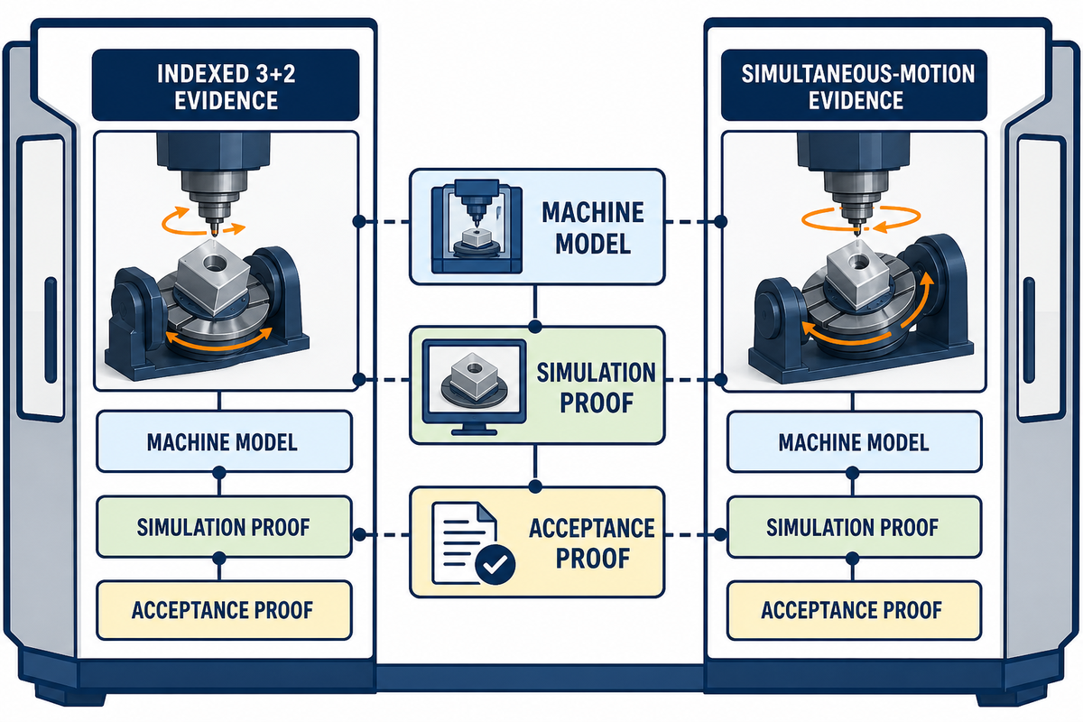
Indexed 3+2 and simultaneous five-axis are two operating modes inside an already selected five-axis process. In 3+2 work, the rotary axes orient the part or tool, stop, and hold that angle while the linear axes cut. In simultaneous work, linear and rotary axes move together during cutting to maintain a changing tool vector.
Release is not about which mode sounds more advanced. It asks whether the posted motion is valid on the named machine and whether the acceptance plan can detect the errors that mode may create.
| Control point | Indexed 3+2 evidence | Simultaneous-motion evidence |
|---|---|---|
| Rotary state during cutting | Commanded angle, lock state, and orientation readback | Coordinated linear and rotary path from posted code |
| Machine model | Rotary centre, limits, fixture, stock, tool, and holder | The same complete model plus kinematic and singularity behavior |
| Transition control | Safe retract, reorientation, clamp state, and datum continuity | Lead-in, lead-out, rotary reversal, feed behavior, and clearance |
| Simulation proof | Actual post output through every indexed move | Actual post output through the full coordinated path |
| Acceptance proof | Cross-orientation relationship tied to drawing datums | Contour or orientation result tied to the model and datum system |
A part can use both modes. Program release should name the mode by operation, retain the same machine and post identity, and preserve a measurement path for the feature each operation creates.
Build a Complete Loaded-Machine Model
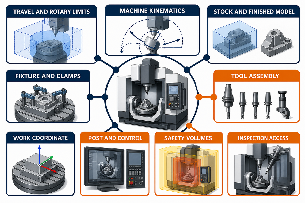
A five-axis simulation is only as complete as the objects and limits inside it. Its machine assembly, rotary centres, stock, fixture, clamps, tools, holders, offsets, travel limits, and control behavior must describe the released production configuration rather than a convenient generic model. The release checklist below is a practical synthesis of the machine, control, and measurement relationships documented in the NIST five-axis metrology program report.
Use dimensions instead of the adjective “complex.” The hypothetical Orion Bracket identifies a 160 mm loaded envelope, an 85 mm pocket, a 125 mm tool assembly, 12 mm minimum holder clearance, a 35° port, a 20 kg blank, a 0.05 mm position tolerance, and a 0.02 mm profile tolerance. Those inputs make collision and measurement questions testable without turning the example into a route recommendation.
| Model element | Required release input | Failure if omitted | Evidence |
|---|---|---|---|
| Machine kinematics | Axis directions, rotary centres, pivots, and signs | Posted angles or tool-centre motion do not match the real machine | Machine-model identity and verification record |
| Travel and rotary limits | Linear strokes, angular ranges, speed, and acceleration boundaries | Overtravel, reversal, or unreachable orientation | Controller and simulation limit match |
| Stock and finished model | Released geometry, allowance, and revision | False clearance or uncut material | Model and drawing revision pair |
| Fixture and clamps | Bodies, fasteners, clamp positions, and allowed states | Collision or inaccessible orientation | Released setup model and clamp sequence |
| Tool assembly | Cutter, extension, holder, gauge length, and clearance body | A tool tip clears while the holder collides | Tool-list revision and measured assembly |
| Work coordinate | Datum origin, orientation, probing sequence, and offsets | Valid motion is executed from the wrong transform | Setup sheet and probe qualification |
| Post and control | Named post version, controller options, and transformation mode | CAM intent becomes different axis motion | Post qualification against the named control |
| Safety volumes | Spindle, head, table, probes, doors, and moving assemblies | Non-cutting collisions remain invisible | Complete machine simulation |
| Inspection access | Probe or gage geometry and datum alignment | The feature can be cut but not proven | Inspection plan and returned record |
Version the model with the posted program. A collision-free result from an older fixture, shorter holder, different rotary-centre calibration, or generic controller configuration is not release evidence for the current part.
Machine Configuration Changes the Loaded Work Envelope
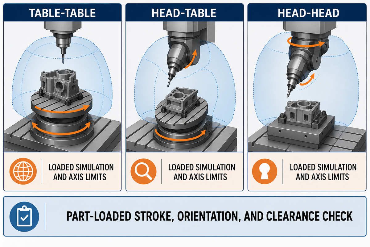
Table-table, head-table, and head-head machines place the two rotary axes in different parts of the kinematic chain. That placement changes what rotates, where mass sits, and which combinations of part, fixture, holder, and tool can move without exceeding travel or creating interference.
Peer-reviewed setup-position research derives separate kinematic transforms for all three architecture families. Its physical case also shows why a machine label is insufficient: the machinable domain had to exclude axis overtravel and interference. Those movement and time results belong only to the tested machine and channel feature, so they aren’t used as buyer defaults here.
A Siemens-coauthored study using SinuTrain reports data from “80.000” simulations—80,000 using an English thousands separator, for one workpiece family on one five-axis machine. Collision-free space changed with geometry, X/Y/Z placement, and rotary orientation. Its high model score validated that study’s approximation; it didn’t create a universal envelope rule.
For the Orion Bracket running example, a configuration decision would therefore compare the 160 mm loaded envelope, 20 kg blank, fixture, 125 mm tool assembly, and 35° port against the actual rotary limits and collision model. No machine family name can close that check by itself.
| Architecture family | What moves | Access question | Evidence |
|---|---|---|---|
| Table-table | Both rotary axes move the workpiece | Will part mass, fixture height, and tilt consume the usable envelope? | Loaded simulation and axis limits |
| Head-table | One rotary axis moves the tool; one moves the workpiece | Where do head, holder, fixture, and table interfere? | Full machine and tool-assembly model |
| Head-head | Both rotary axes move the tool | Can the head reach around the part without losing stroke or stiffness? | Part-loaded stroke, orientation, and clearance check |
Do not assume two machines with the same architecture expose the same loaded envelope. Verify the actual drawing, stock, fixture, tool assembly, rotary limits, offsets, and acceptance method on the named production configuration. Machine safeguarding, energy isolation, maintenance, and operator procedures remain the machine owner’s and facility’s responsibilities; a digital model does not replace them.
The Machine–Post–Program Consistency Check
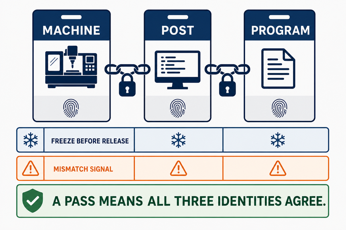
The Machine–Post–Program Consistency Check tests whether three release identities describe the same physical process. Machine identity fixes kinematics and control options. Post identity fixes how tool-centre intent becomes axis commands. Program identity fixes the executable code that was simulated, proved out, and approved. This separation follows the machine-bound and tool-centre program distinction examined in the joint Boeing–NIST STEP-NC portability validation.
| Identity | Freeze before release | Mismatch signal | Required record |
|---|---|---|---|
| Machine | Model, serial or asset identity, control, options, calibration state, and rotary-centre definition | The simulation uses different limits, signs, pivots, or transformation behavior | Approved machine-model version and verification date |
| Post | Post name, version, configuration, and controller target | The same CAM path creates different rotary moves or work offsets | Post qualification test and approved checksum or revision |
| Program | Released code, tool list, setup, work offsets, and linked drawing revision | Production runs code other than the simulated or proved-out file | Program release record and change history |
A PASS means all three identities agree and their evidence is current. A post update, machine calibration change, controller option change, or program edit breaks the chain and requires a proportionate revalidation before production resumes.
Key takeaway
A five-axis program is release-ready only when its machine model, post-processor, executable code, and inspection path refer to the same controlled configuration.
Programming Is a Control Chain, Not a CAM Button
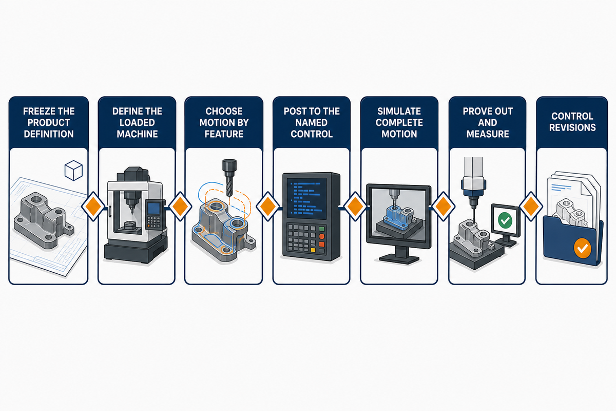
Valid-looking cutter paths can still fail on the machine. Programmed tool vectors must pass through a machine-specific kinematic transformation, a qualified post-processor, controller behavior, real axis limits, and the complete collision model. Each handoff can change the result.
The joint Boeing–NIST STEP-NC portability validation separates machine-bound axis-movement programs from higher-level tool-centre information. That distinction explains why a program cannot be judged by a CAM screen alone: the post and machine model convert intent into executable axis motion.
US12001188B2, granted in 2024, further shows that five-axis volumetric-error compensation can enter the control chain. Its listed assignee is Chengdu Aircraft Industrial Group Co., Ltd.; the record is cited as attributed technology evidence and does not imply Zhenling ownership, licence, or use.
- Freeze the product definition — bind the model, drawing revision, material condition, datums, and acceptance notes.
- Define the loaded machine — include axis directions, rotary centres, travels, table or head limits, fixture, stock, tools, and holders.
- Choose motion by feature — state where fixed indexing is enough and where a changing tool vector is required.
- Post to the named control — qualify the post-processor against the machine and controller configuration.
- Simulate complete motion — check stock, holder, fixture, spindle or head, moving machine parts, overtravel, and transitions.
- Prove out and measure — use a controlled release, verify the risk features, and record deviations before production.
- Control revisions — link program, post, tool list, setup, and inspection evidence to the same approved revision.
Ask what evidence closes each step. “We simulated it” is incomplete unless the simulation used the actual post output and a current machine model. “We probed it” is incomplete unless the probe strategy is tied to the drawing datum and the returned result.
Advanced CNC machining operations also depend on people and boundaries. Machinists need to know which axis controls are active, programmers need current machine components and machine capacity in the model, and production needs revision ownership. Machine data inside the CNC system must match the released configuration. Automation or automation solutions can carry data between systems, but they do not make an unqualified 5-axis solution safe. That rule applies to 5-axis capability claims, 5-axis CNC milling machines, and any newer machining technology: prove the chain on the named configuration.
Tolerance Is a Machine-Specific Error Budget
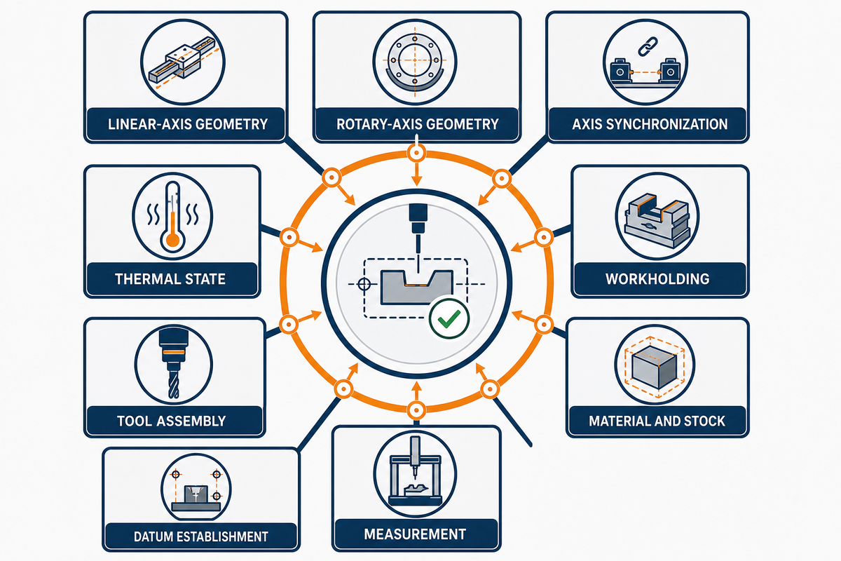
Reducing reclamps may remove one transfer error, but five-axis motion introduces no blanket accuracy guarantee. Rotary-axis geometry, synchronized motion, thermal state, tool reach, workholding, material response, probing, and external measurement can all contribute to the accepted feature result.
ISO 230-12:2022 identifies linear- and rotary-axis geometric errors, synchronization, dynamic contouring, and thermal behavior as potential contributors to errors seen in finished test pieces. ISO 230-1 has a narrower geometric/no-load scope and excludes several operating effects. Those boundaries make the test method as important as the number reported.
Evidence follows three layers. First, kinematic or no-load tests characterize machine behavior. Second, ISO 10791-7 uses standardized finished test pieces, including a freeform five-axis test piece, to assess cutting accuracy under stated conditions. Third, the buyer’s actual part needs drawing-specific conformity evidence. That middle layer is stronger than a no-load test, yet it is still not the buyer’s part.
| Contributor | Mechanism | Control point | Evidence and limit |
|---|---|---|---|
| Linear-axis geometry | Position, straightness, and squareness error | Calibration and machine condition | Machine test; transfer to part remains conditional |
| Rotary-axis geometry | Axis location and orientation error | Kinematic measurement and compensation | Rotary or coordinated-motion test |
| Axis synchronization | Following and contour error during motion | Controller, path, and feed strategy | Dynamic test or bounded cut result |
| Thermal state | Machine and workpiece drift | Warm-up, environment, and process timing | Recorded condition; no universal correction |
| Workholding | Clamp distortion or movement | Fixture support, clamp sequence, and force | Setup record and feature checks |
| Tool assembly | Deflection, runout, wear, and holder interference | Reach, holder, cutting conditions, and life control | Tool list, offsets, and monitored result |
| Material and stock | Residual stress, hardness, and removal sequence | Material condition and roughing plan | Material record and intermediate checks |
| Datum establishment | Probe, offset, or transfer inconsistency | Datum strategy and probe qualification | Setup and probing record |
| Measurement | Method, access, alignment, and uncertainty | Inspection plan and decision rule | Feature result with stated method and limits |
Feature acceptance comes from an owned error budget and a suitable measurement decision. Machine testing can characterize one contributor, but it cannot transfer conformity to a production part without the remaining process and measurement evidence.
Match Inspection Evidence to Rotary-Axis Risk
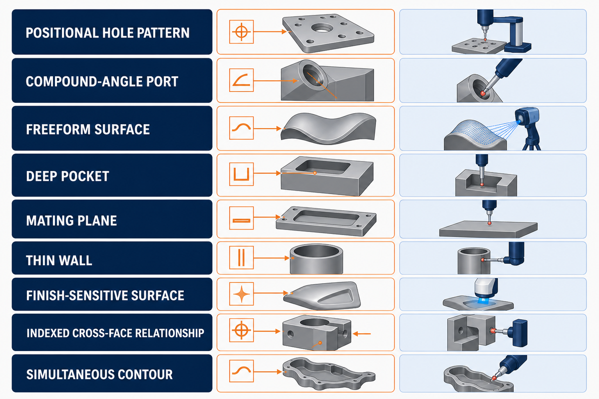
Inspection should be planned from the feature relationship that can reject the part. Generic reports may list dimensions yet miss the shared datum, compound orientation, freeform deviation, or surface condition that governs assembly. Define the method and returned record before production starts. The aerospace feature-proof guide shows how application risk changes the depth of that evidence.
NIST’s current coordinate-measuring-machine digital-twin work treats motion and inspection information as structured, standards-based data. That direction is useful, but a buyer still needs the right method for the feature. In-process probing can support setup control without replacing an independent final measurement where the contract requires one.
| Feature or relationship | Datum focus | Candidate method | Record and limitation |
|---|---|---|---|
| Positional hole pattern | Drawing datum reference frame | Coordinate measurement or suitable calibrated gaging | Position result; confirm probe access and alignment |
| Compound-angle port | Axis and intersection to datums | Coordinate measurement or dedicated fixture | Orientation and location; internal access may limit sampling |
| Freeform surface | Model-aligned datum system | Scanning or defined point set | Deviation map; point density and alignment rule matter |
| Deep pocket | Floor and wall relationship | Long-stylus coordinate measurement or qualified gage | Depth and wall result; stylus access can add uncertainty |
| Mating plane | Primary datum and mating features | Surface plate, coordinate measurement, or form system | Flatness or orientation; support condition must match the plan |
| Thin wall | Free-state or restrained condition | Low-force contact or optical method where suitable | Thickness and form; restraint condition can change the answer |
| Finish-sensitive surface | Specified sampling direction and area | Calibrated surface measurement | Parameter and trace; cutoff and location must be defined |
| Indexed cross-face relationship | Shared datum across orientations | Single aligned coordinate setup where possible | Relationship result; avoid isolated checks that lose the datum link |
| Simultaneous contour | Model and functional datums | Scanning, section checks, or functional gage | Contour evidence; define alignment and acceptance rule |
For results near a specification limit, the buyer and supplier should also agree how measurement uncertainty enters the conformity decision. Measured values alone aren’t always complete accept-or-reject instructions. Put the method, uncertainty expectation, and decision rule in the inspection plan when the risk warrants it. For a structured handoff, the critical-feature transfer builder can help identify which drawing relationships need an owned record; it is an input tool, not evidence that a feature conforms.
The 7-Point Rotary Error Release Check
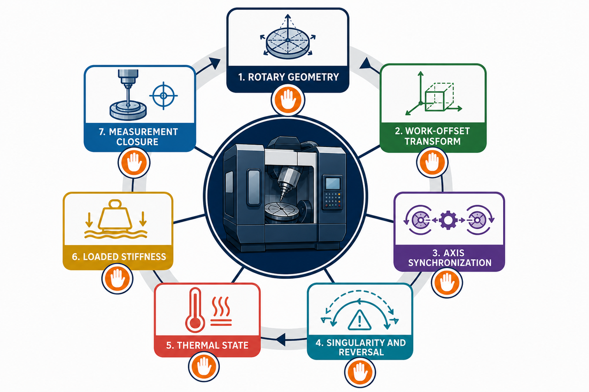
The 7-Point Rotary Error Release Check turns a broad accuracy claim into seven machine-specific questions. It is used after the process and machine are named, before a production program is released. Passing requires evidence for each applicable point; one clean test value cannot stand in for the complete chain. The seven points are a release-oriented synthesis, informed by the machine-tool motion tests catalogued in ISO 10791-6 and the test-piece evidence scope of ISO 230-12.
| Release point | Question | Evidence | Revalidation trigger |
|---|---|---|---|
| 1. Rotary geometry | Are rotary-axis location and orientation errors characterized for the named machine? | Current kinematic test, calibration, and compensation state | Calibration, service, crash, or geometry drift |
| 2. Work-offset transform | Does the probed datum produce the same transform used by the post and control? | Setup sheet, probing routine, offsets, and test feature | Fixture, datum, probe, or offset change |
| 3. Axis synchronization | Are contour and following errors acceptable during coordinated motion? | Dynamic test or bounded production-like cut | Control tuning, feed strategy, or motion-profile change |
| 4. Singularity and reversal | Do orientation changes cause rotary acceleration, reversal, or feed behavior that threatens the feature? | Posted-path review, simulation, and controlled prove-out | Tool-axis strategy, post, or orientation change |
| 5. Thermal state | Is the machine and workpiece condition consistent with the qualified process window? | Warm-up, environment, timing, and drift record | Long idle, environmental shift, or changed duty cycle |
| 6. Loaded stiffness | Do tilted workpiece, tool reach, clamping, and cutting load change the result? | Fixture record, tool assembly, cutting conditions, and risk-feature result | Stock, fixture, tool, holder, or cutting-condition change |
| 7. Measurement closure | Can the inspection method detect the feature error with an agreed decision rule? | Method, uncertainty expectation, datum alignment, and returned result | Feature, tolerance, method, or acceptance-rule change |
This check is not a universal calibration interval or tolerance promise. Its purpose is to expose which evidence is current, which condition changed, and where a production release must stop for revalidation.
Close the Revision-to-Part Proof Loop
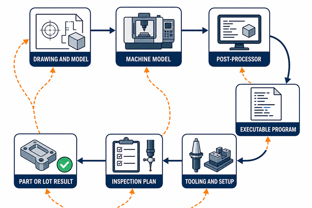
The Revision-to-Part Proof Loop keeps an approved five-axis process from drifting after prove-out. It begins with the released product definition, passes through the exact machine, post, program, tools, setup, and inspection plan, and ends with a result traceable to the produced part or lot.
| Controlled link | Identity to retain | Release evidence | Change response |
|---|---|---|---|
| Drawing and model | Revision, material condition, datums, and acceptance notes | Approved product definition | Reassess affected operations and inspection |
| Machine model | Machine asset, kinematics, limits, control, and calibration state | Verified model version | Revalidate after configuration or geometry change |
| Post-processor | Post name, version, options, and target control | Qualification result and approved revision | Retest the affected transformations and motion |
| Executable program | File revision or checksum and linked operation plan | Simulation and prove-out record for that file | Invalidate prior simulation when code changes |
| Tooling and setup | Fixture revision, clamps, tool assemblies, offsets, and probing routine | Released setup sheet and measured tool data | Repeat clearance and risk-feature checks |
| Inspection plan | Method, datum alignment, sampling, uncertainty expectation, and decision rule | Approved plan and method capability | Reconfirm method suitability after feature or tolerance change |
| Part or lot result | Part, lot, program, setup, machine, and inspection identifiers | Traceable acceptance record and deviations | Contain affected output and reopen the relevant link |
Organizations do not need to use the same software to close the loop. Identities and changes must still remain reconstructable. A PDF report without the program, setup, machine, part, and method links is a result document, not a complete process trace. For early builds, the prototype evidence planning tool offers a separate way to organize validation inputs without replacing the controlled records.
Connected 5-Axis Evidence Is a 2026 Opportunity, Not a Finished System
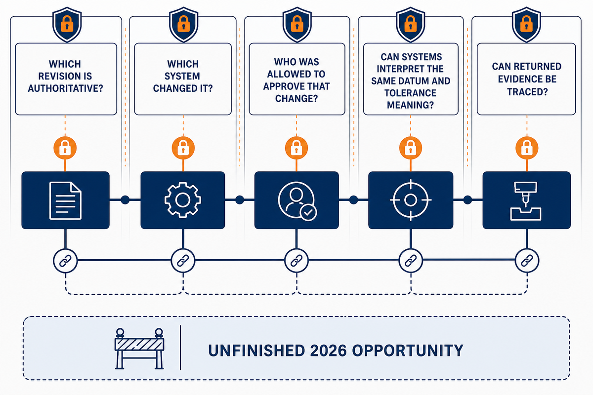
A useful 2026 shift is toward connected process evidence, but the system is unfinished. Controls, machine models, CAD/CAM, post-processors, simulation, telemetry, probing, and inspection can share more context than before. Buyers should test whether those links remain interpretable, traceable, and trustworthy.
MTConnect’s five-axis model exposes linear and rotary positions alongside load, temperature, spindle, path, tool, coolant, and production states. NIST’s coordinate-measurement work points toward structured links between motion and inspection data. Together, they show a technical direction in which process events can be connected to evidence.
NIST also documents the counterweight. Standards and tools still have gaps in representation and semantic conformance. Product data needs authorization, authentication, traceability, and protection against intentional or accidental tampering. Connected chains can propagate bad revisions faster if trust controls are weak.
So the buyer should ask five questions: Which revision is authoritative? Which system changed it? Who was allowed to approve that change? Can the manufacturing and inspection systems interpret the same datum and tolerance meaning? Can returned evidence be traced to the released program, setup, and part lot?
Connected evidence should therefore be treated as a controlled implementation problem, not a finished product claim. A useful outcome is a reconstructable link from approved definition to posted motion and measured part—not the mere presence of a dashboard or telemetry feed.
Frequently Asked Questions
These concise answers apply the same machine-specific evidence boundary used above; the underlying distinction between tool-centre intent and machine-bound execution is documented in the joint Boeing–NIST STEP-NC portability validation.
What must a five-axis machine model include?
Include the named machine’s axis directions, rotary centres, travel and angular limits, table or head geometry, controller behavior, stock, fixture, clamps, complete tool assemblies, work offsets, probes, and other moving collision bodies. The model revision should be linked to the posted program and the released setup. Generic geometry is not sufficient release evidence.
How do you validate a five-axis post-processor?
Qualify the post against the named machine and controller configuration. Test representative indexed positions, simultaneous paths, work-offset transforms, rotary limits, reversals, retracts, and error handling. Compare posted axis motion with the intended tool-centre path, then retain the approved post revision with the program release record. Qualification should also cover safe transitions, controller transformations, limit behavior, and expected alarms. A passing sample on one machine-and-control pair does not automatically transfer to another configuration. Repeat affected tests after a configuration change.
What is a rotary-axis singularity in five-axis machining?
A singularity is a kinematic condition where small tool-orientation changes can demand large or unstable rotary-axis motion. Near that condition, the machine may reverse, accelerate, slow the feed, or choose another orientation solution. No universal angular threshold applies because architecture, axis limits, controller logic, post settings, and tool-axis strategy interact. Review rotary speed, reversal, feed behavior, clearance, and alternative orientation solutions in the actual posted code. If a path approaches a problematic condition, the programmer may need to change the tool-axis strategy, split the operation, or qualify a controlled transition. The post, controller, and prove-out must handle the machine-specific behavior.
Does collision-free CAM simulation prove the posted program is safe?
No. Release evidence should simulate the actual post output with the current machine model, limits, fixture, stock, tools, holders, offsets, and non-cutting transitions. A toolpath-only view can miss rotary overtravel, head or holder collisions, clamp states, controller transforms, and safe-retract problems. Controlled prove-out and machine safeguards still remain necessary before production.
Which five-axis process changes require revalidation?
Revalidation is proportionate to the affected link. Drawing, machine geometry, calibration, controller options, post version, program code, fixture, tool assembly, offsets, probing, cutting conditions, or inspection-method changes can invalidate earlier evidence. A drawing change may require only affected operations and features to be reviewed, while a changed rotary-centre definition or post transformation can affect the complete program. Fixture or holder changes reopen loaded-envelope and collision checks. Calibration or control changes reopen kinematic and synchronized-motion evidence. Inspection changes reopen datum alignment, method suitability, and the acceptance rule. Use the Revision-to-Part Proof Loop to identify which simulation, prove-out, or measurement checks must be repeated, then record the reason, scope, result, and approval for the new release.
What inspection record closes a five-axis evidence chain?
An inspection record should identify the part or lot, drawing and model revision, datum alignment, measurement method, sampling, relevant uncertainty or decision rule, result, machine, setup, program, and any deviation. Depending on the risk, it may also need the probe or gage identity, calibration state, alignment rule, point strategy, environmental condition, and disposition authority. Exact fields depend on the contract, but the result must remain traceable to the same controlled process that produced the part.
References
References & Sources used in this guide are listed below in order of first use.
- ISO 10791-6:2014, Accuracy of speeds and interpolations.
- ISO 230-12:2022, Accuracy of finished test pieces.
- ISO 10791-7:2020, Accuracy of finished test pieces.
- NIST five-axis metrology program report.
- NIST canonical machining commands.
- Five-axis workpiece setup-position study.
- Five-axis workpiece setup and collision-space study.
- Joint Boeing–NIST STEP-NC portability validation.
- US12001188B2 five-axis volumetric-error compensation patent record.
- NIST coordinate-measuring-machine digital-twin research.
- NIST Digital Thread for Manufacturing.
- MTConnect five-axis device-model playground.
Release a named configuration, not an axis label
Bind the loaded-machine model, post, executable program, setup, rotary error checks, and inspection record to the same revision. If you need a commercial review after that technical preparation, use the service handoff below.