Get in touch with Zhenling Company

By DD · Updated August 2026
Design for CNC Machining (DFM) is the discipline of translating part function into geometry, material state, machining access, workholding, measurement, and an acceptance decision. Machinability is not established merely because a cutter can reach a feature. Release also requires the feature to be held, produced, measured, and accepted under a defined plan.
This guide replaces “CNC-friendly” dimensions with questions a design engineer, sourcing manager, and quality engineer can resolve together. Public standards, metrology sources, and condition-bound experiments support those questions. No universal wall, pocket, tolerance, setup, or savings value is claimed, and no private Zhenling production result is presented.
Intent note: This CNC machining design guide addresses part manufacturability and CNC machining parts. Buyers and engineers can use it as a CNC design guide; it is not a source of CNC machine design files or a CNC machine design software tutorial.
What CNC DFM Needs to Improve
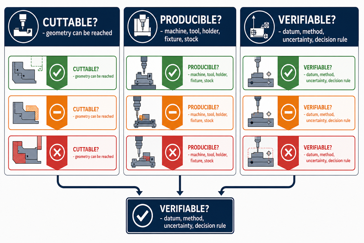
CNC DFM should improve the probability that a released design can move through machining and inspection without changing its intended function. That requires more than simplifying the computer-aided design model. Reviewers must expose access, support, datum transfer, process state, measurement access, and the evidence used for acceptance.
Start by separating three questions. Is the feature geometrically cuttable? Can the planned machine, tool, holder, fixture, and stock produce it without an unexamined failure mode? Can the finished requirement be verified with the stated datum, method, uncertainty treatment, and decision rule? Answering the first question does not answer the other two.
Design for manufacturing is broader; CNC machining DFM narrows it to this process family. In the design phase, design for manufacturability connects initial design intent to the manufacturing process. Product design DFM tests whether part design choices, specific design features, and design limitations support the no-change function. DFM principles are neither universal design rules nor design for assembly. These design considerations keep design decisions, the design process, manufacturing design, release authority, and design flexibility traceable.
This boundary matters because a drawing standard is a design language, not proof of shop capability. ASME’s public Y14.5 overview describes rules for dimensioning, tolerancing, datums, and related practices. Shop release still needs a route and an inspection plan for the actual feature.
Evidence capsule: Berez, Webster, and Ottway surveyed 67 instructors-of-record in United States post-secondary engineering and engineering technology programs. Dimensioning and tolerancing was mandatory for approximately three quarters of students, but fewer than one third consistently received geometric dimensioning and tolerancing instruction. This finding supports an explicit review packet, not a judgment about any individual engineer.
Use the 5-Step DFM Change-Authority Path
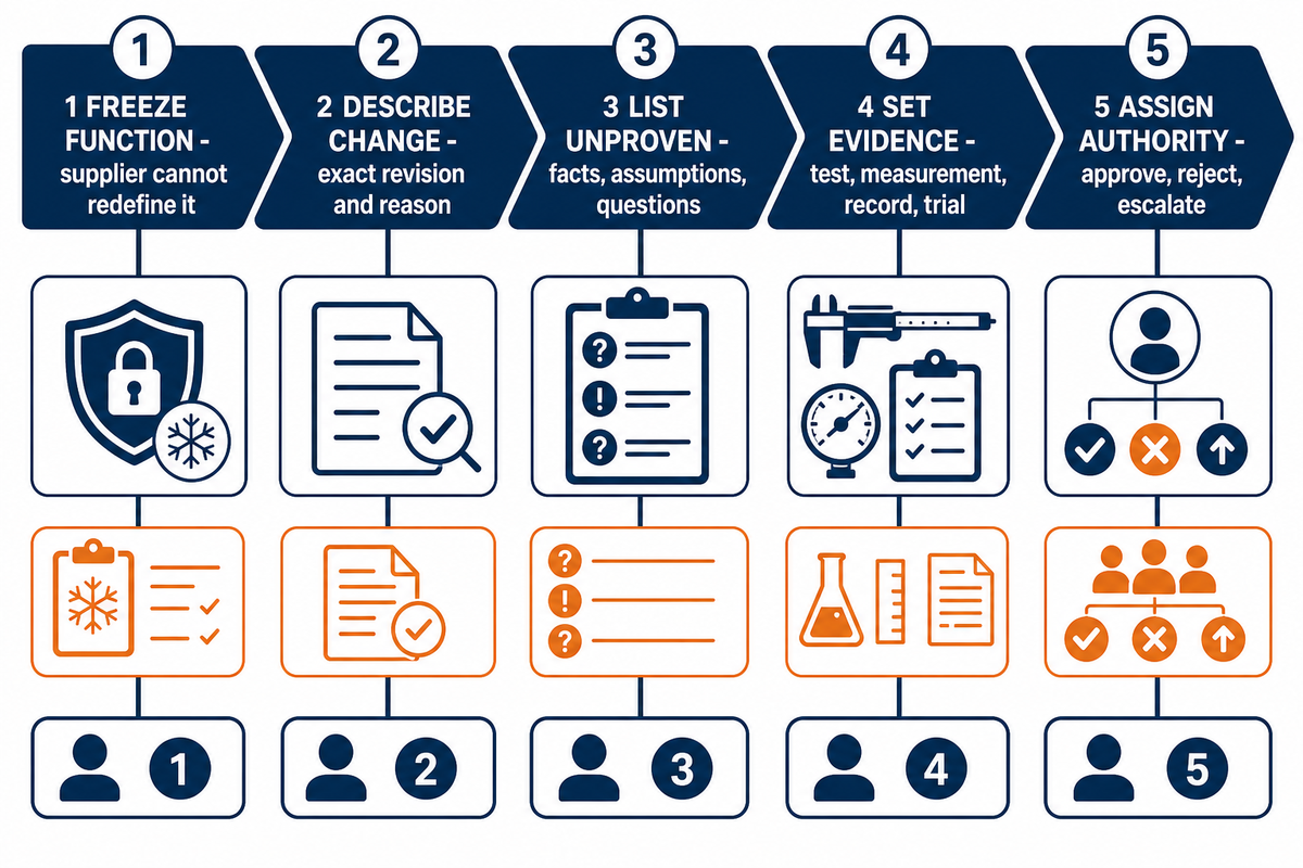
The DFM Change-Authority Path is a five-step approval test for any supplier-proposed design revision. It separates what manufacturing may recommend from what design or quality may release. If an assumption remains unresolved, the response ends in a question, trial, or escalation instead of silently revised geometry. The NIST inspection-planning rule model illustrates why approval evidence must reflect measurement resources and uncertainty.
- Freeze the protected function — state what the released part must do and what the supplier cannot redefine.
- Describe the proposed change — record the exact revision being requested and the reason for it.
- List what remains unproven — separate verified facts from route assumptions and unresolved questions.
- Set the approval evidence — name the test, measurement, record, or trial needed before disposition.
- Assign authority and disposition — identify who may approve, reject, or escalate the change and bind that decision to the revision.
Hypothetical sealing-pocket revision: suppose a drawing uses sharp internal corners and a blanket tight tolerance around a sealing pocket. Pocket function may depend on the sealing surface and selected interfaces, not on a mathematically sharp corner. Safe review asks whether a reachable internal radius preserves sealing, which dimensions are functional, which datum controls inspection, and what method can verify the released requirement. This is a hypothetical decision pattern, not a Zhenling customer result or a promised saving.
Do
- Preserve the protected function
- Write the proposed change and reason
- List the approval evidence gap
- Name the decision authority
Don’t
- Let a supplier redefine function
- Approve a revision without an owner
- Convert screening output into approval
- Mix a quotation with design release
Design for Tool Access and Fewer Setups
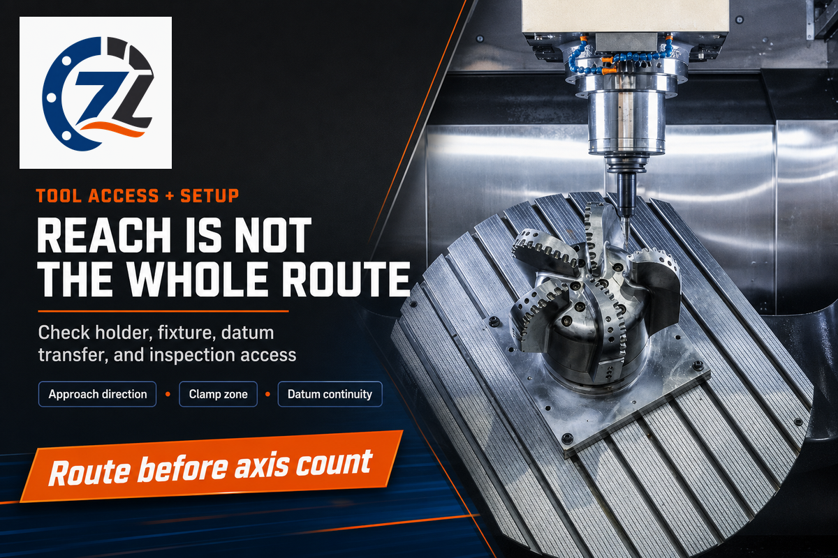
Tool access should be evaluated with clamping and datum continuity, not as a free-space problem. Model-space reachability may conflict with the holder, fixture, stock, or inspection probe. Fewer setups can help, but only when the selected route remains rigid and measurable.
Map every critical feature to an approach direction and holder envelope. Then mark clamp zones, protected surfaces, stock allowances, and the datum used before and after reorientation. Multiple orientations may add non-cutting work, new workholding, datum transfer, and another inspection state. A four-axis or five-axis route may reduce reorientation, yet it can introduce different clearance and rigidity constraints.
DFM for CNC machining describes the CNC machining process by machining operation: CNC milling, turned parts, milled parts, or 3+2 machining on multi-axis machines. Record CNC tools, CNC equipment, machining setups, and machining strategies. This turns common CNC and standard CNC labels into a route. Using CNC may reduce machining handoffs, while added orientation can increase machining time, machine time, and extended machining times.
Keep the axis decision separate from the drawing decision. This guide to how 3-, 4-, and 5-axis machining routes differ can help frame access. Review packets still need to state which faces, datums, and inspection steps must remain related.
Evidence capsule: Kip Hanson’s signed trade-press discussion treats 5-axis access and rigid workholding as a coupled problem. It supports checking multi-side reach before choosing the number of setups; its fixture dimensions and clamping-force values describe named products and are not transferred here.
Design Internal Corners, Pockets, and Reach as One System
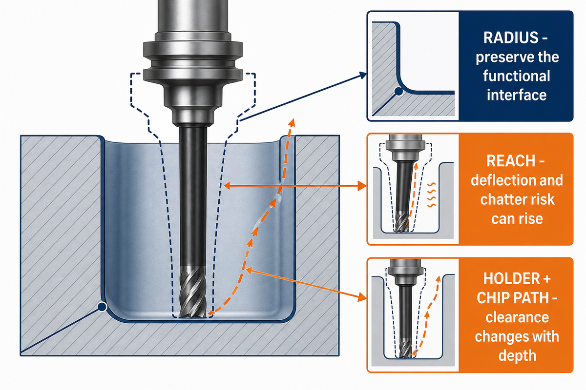
An internal corner or deep pocket cannot be reviewed from radius or depth alone. Its useful envelope includes cutter diameter, flute length, tool reach, holder clearance, corner engagement, chip evacuation, material, workholding, toolpath, finish requirement, and the method used to inspect the result.
Rotating cutters leave an internal radius. Increasing that radius may permit a larger and stiffer tool, but the functional interface and adjacent features remain controlling. Deeper pockets can require more reach; reach can raise deflection and chatter risk; corner engagement can change load; and a holder that clears the opening may still collide deeper in the path. Copying a depth-to-diameter ratio hides those dependencies.
Use provider ratios only as questions for a drawing-specific tool envelope. Ask which tool and holder are assumed, where the flute ends, how chips leave the pocket, which surfaces are critical, and whether the feature is inspected in-process or after release. Do not convert a competitor’s guideline into an industry limit.
When engineers design parts around a particular end mill, the selected tool remains a route assumption rather than a product requirement. Tighter tolerances should stay attached to function, measurement, and mating parts instead of being used to justify a preferred cutter.
Evidence capsule: A 2025 7075-T651 study used 12 mm two- and three-flute end mills, cutting speeds from 300 to 900 m/min, and feeds from 0.025 to 0.125 mm/tooth. In its Figure 7 comparison, fixed at 3 mm amplitude and a 30 mm profile term, two-flute deflection exceeded 0.12 mm at the maximum tested speed and feed; the three-flute maximum did not exceed 0.09 mm. Cutter runout was not included in the model.
Review Walls, Holes, Threads, and Small Features by Failure Mode
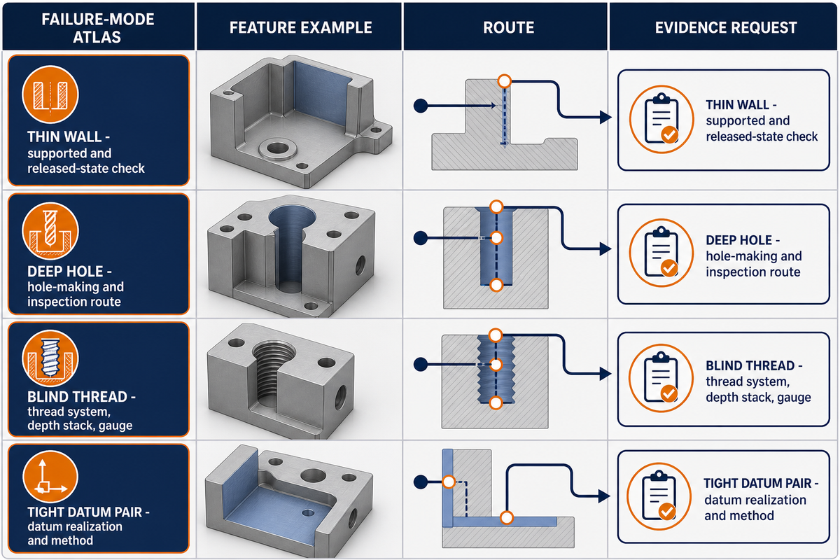
Small and slender features should be routed by likely failure mode, not by one minimum dimension. Walls may deflect or spring after release; holes may suffer access, exit, evacuation, or measurement problems; blind threads consume depth in drill-point, lead-in, and clearance zones; small tools may be available but unstable.
The matrix below is a clustering tool for a design review. It does not predict failure. Each row links a feature to the hidden condition that must be made visible before a designer accepts a revision or a buyer compares quotations.
| Feature category | Hidden condition | Likely consequence | Evidence or decision to request |
|---|---|---|---|
| Multi-face feature | Approach and clamp conflict | Reorientation or datum transfer | Setup and datum map |
| Internal corner | Functional radius and tool size | Small cutter or extra operation | Interface function and tool envelope |
| Deep pocket | Reach, holder, chip path | Deflection, chatter, recutting | Tool, holder, path, finish plan |
| Thin wall | Span, height, support, release | Deflection, vibration, springback | Supported and released-state check |
| Deep hole | Process and evacuation mechanism | Debris, drift, surface damage | Hole-making and inspection route |
| Blind thread | Drill point, tap lead-in, relief | Reduced usable engagement | Thread system, depth stack, gauge |
| Undercut | Tool form and side access | Special tool or added setup | Tool concept and access direction |
| Narrow slot | Tool stiffness and chip space | Breakage or unstable finish | Available tool and test condition |
| Tight datum pair | Same-setup relationship | Transfer and measurement burden | Datum realization and method |
| Texture zone | Parameter, direction, instrument access | Different process or inspection scope | Texture parameter and method |
| Engineering plastic feature | Thermal response and support | Movement or smeared edge | Grade, state, tool, elapsed time |
| Stress-sensitive stock | History, heat treatment, removal balance | Distortion after release | Stock record and staged observation |
Three recent studies show the reasons that the envelope must go with the number. The values below are evidence examples, not design recommendations.
| Material and feature | Test envelope excerpt | Transfer boundary |
|---|---|---|
| 7050-T7451 wall | 1, 1.5, and 2 mm walls; 48 mm axial depth; 0.2 mm radial finishing depth; 300, 600, and 900 m/min | Only the named alloy, geometry, toolpath, workholding, and parameters |
| Inconel 625 wall | 1 mm thickness, 16 mm height, three 10 mm cutters, a controlled 2.03 cm³/min removal rate, and observed maximum deviations of 0.08 mm and 0.14 mm in two named conditions | Cutter and strategy comparisons inside that experiment; the authors reported that SECO Tools supplied the cutters and declared no conflict of interest |
| HDPE orthogonal cut | 60, 120, and 180 µm nominal depths at 10 mm/min | Polymer force and chip modeling, not a metal feature rule |
Thread form and process planning are separate layers. Once a metric or unified-inch system is selected, its normative form and tolerance rules apply. The process plan must still reserve drill-point and tap lead-in depth, provide clearance and evacuation, and name the gauge or measurement method. A “standard thread” label does not answer those questions.
Evidence capsule: One aluminum study reported about 0.06 mm free-edge deflection for a 130 × 2.5 × 60 mm wall cut with a 12 mm four-flute tool. Another 7050-T7451 study compared 1, 1.5, and 2 mm walls at 48 mm axial depth, 0.2 mm finishing radial depth, and 300, 600, and 900 m/min. Both are experiment envelopes, not transferable minimums.
Specify Tolerances, Datums, and Surface Finish Selectively
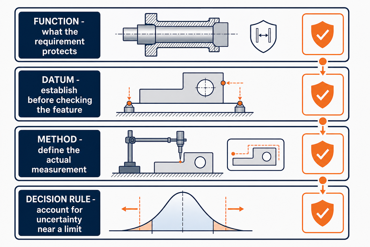
A tolerance becomes useful acceptance evidence only when its function, datum, process state, measurement method, uncertainty treatment, and decision rule are defined. Blanket tight tolerances can add machining and inspection burden while leaving the real interface or texture requirement ambiguous.
Separate dimensional size, geometric control, and surface texture. Then reconnect them through the actual measurement. A datum-referenced result needs the datum to be established; a texture callout needs a parameter and method; a value near a specification limit may need an uncertainty-aware conformity rule. For broader feature-to-route context, use the CNC machining service planning hub; inspection should still begin from the released requirement, not a generic machine accuracy.
Datum-referenced form measurements require setup measurements to establish the datum before the feature is checked.
George Schuetz, Director of Precision Gages at Mahr Inc. and Modern Machine Shop contributor — paraphrased from the cited article
Do not call a process “capable” from one accepted part. An archived NIST/SEMATECH handbook frames capability as a comparison between a stable process and specification limits. It also warns that common indices depend on adequate independent observations and distribution assumptions. Where those assumptions fail, a suitable method and uncertainty statement are needed; this article does not prescribe a current requirement or a generic capability target.
Evidence capsule: This archived handbook is used only to illustrate statistical-method prerequisites. It is not presented as a current regulatory rule, a required lot size, or universal proof of CNC capability.
Let Material, Stock Condition, and Process Qualify Every Geometry Rule
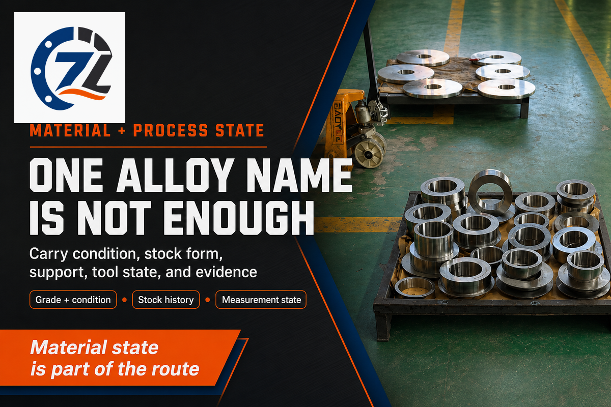
Material identity is necessary but not sufficient. Grade, temper or condition, stock form, prior heat treatment, residual stress, stiffness, thermal response, chip behavior, tool condition, workholding, and the selected process can change which geometry is practical and which evidence is needed.
Rules derived from one aluminum alloy cannot automatically govern stainless steel, titanium, nickel alloy, or engineering plastic. Even within one family, stock history and restraint can matter. Carry the material specification and substitution authority into every wall, pocket, finish, and tolerance decision. The constraint-led CNC material selection guide provides a broader material-screening framework; the current drawing remains controlling.
Polymer evidence makes the transfer problem visible. A 2022 HDPE study made experimental cuts at 60, 120, and 180 µm nominal depths and 10 mm/min. Its separate two-dimensional finite-element model used the measured stress-strain curve to predict cutting force and chip formation at 10 mm/s. Neither condition can become a metal rule. Likewise, titanium stock history and heat treatment can change residual-stress and deformation behavior without establishing a general titanium minimum.
Capability language needs the same discipline. Precision CNC machining, generic machining services, or claimed machining capabilities and CNC capabilities do not by themselves validate CNC design. CNC machining design should connect design geometry, machining design, machining tolerance, and the responsible measurement plan. Treat broad design guidelines, DFM guidelines, guidelines for CNC machining, and claims about common machining as prompts until the shop’s actual route and evidence are named.
Evidence capsule: A NIST-hosted Ti-6Al-4V experiment covered cutting speeds from 20 to 100 m/min. Apparent tool-chip temperature increased with speed, while the temperature distribution varied across chip width and tool condition affected interpretation. The result qualifies process reasoning; it does not rank materials or set a design limit.
Translate DFM Decisions into Three Cost-Evidence Layers
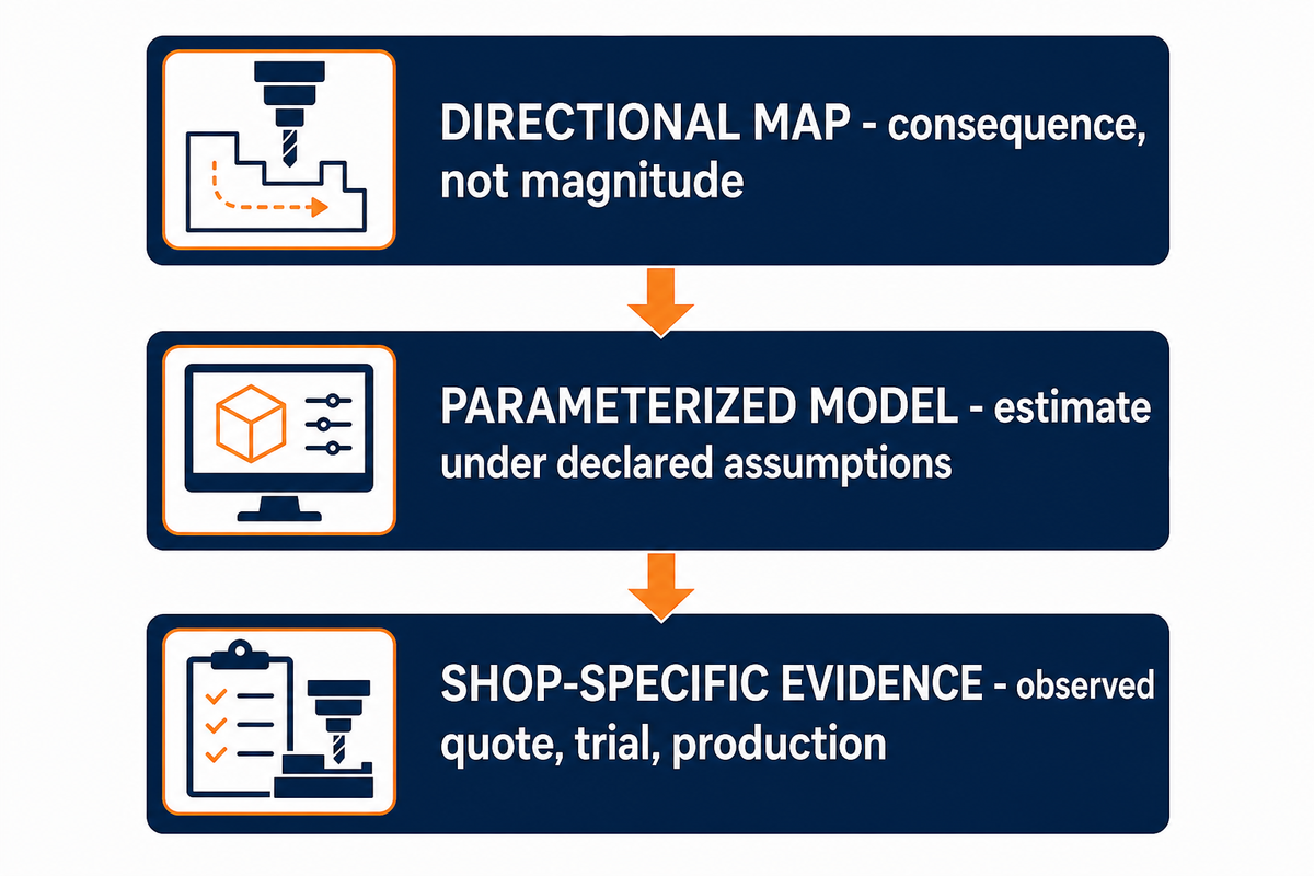
Cost claims should be classified before they are used. A DFM review can show a directional consequence, a parameterized model can estimate time or cost from declared inputs, and a shop-specific record can show an observed quote or accepted-production result. These are different evidence levels.
| Evidence layer | What it can say | Minimum inputs | What it cannot prove |
|---|---|---|---|
| Directional causal map | A choice may add setup, tool, inspection, or rework exposure | Feature, route, quantity, acceptance scope | Magnitude or guaranteed saving |
| Parameterized model | Estimated time or cost under declared assumptions | Resources, parameters, rates, routing, uncertainty | Observed shop or customer result |
| Shop-specific evidence | Observed quote, trial, or accepted-production outcome | Controlled revisions and comparable acceptance records | Universal expectation for another part |
A deeper pocket may require more reach; a new orientation may add workholding and datum transfer; a tighter requirement may add process control and inspection. Those are causal questions, not automatic cost reductions. Keep the detailed denominator with the accepted-part cost drivers in CNC machining. No public Zhenling before-and-after DFM dataset was supplied for this article, so no percentage is claimed.
Compare lead time and cost using the same number of parts, material, route, inspection, and record denominator. A machined part can shift in machining cost across metal parts, plastic parts, and stock states. For custom parts and CNC machined parts, ask what each part requires. CNC machined components, parts for CNC machining, and assembled parts and products should not inherit a “reduce cost” claim without shop evidence; time and cost remain estimates until the assumptions are declared.
Package the DFM Change for Approval
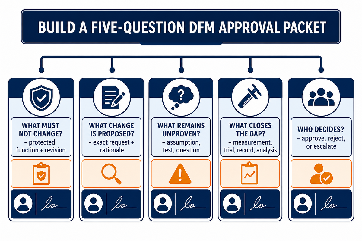
A DFM approval packet should document the decision a supplier cannot own: what function is protected, what change is proposed, what remains unproven, who may approve it, and which revision carries the disposition. Feature, datum, access, setup, and inspection mapping stays with the site’s existing route-planning framework instead of being duplicated here.
| Approval question | Required entry | Decision owner |
|---|---|---|
| What must not change? | Protected function, interface, and released revision | Design authority |
| What change is proposed? | Exact revision request and supplier rationale | Manufacturing and design |
| What remains unproven? | Open assumption, missing test, or unresolved question | Named technical owner |
| What closes the gap? | Required measurement, trial, record, or analysis | Quality or design authority |
| Who decides? | Approve, reject, or escalate; dated and revision-bound | Authorized approver |
Automated DFM software can populate questions, detect represented geometry, and compare a model with encoded rules. It cannot see an unstated material history, unavailable cutter, supplier-specific fixture, measurement access problem, or decision authority unless those are represented. Treat software output as screening until responsible manufacturing and quality personnel accept the assumptions.
Evidence capsule: NIST IR 5713 is a 37-page survey of automated manufacturability analysis that emphasizes computerized design and manufacturing-resource representations plus extensive geometric reasoning. Its scope supports an input-aware screening layer; it does not prove that any 2026 tool covers every machine, fixture, inspection method, or release decision.
For a drawing-specific handoff, send the approval packet with the controlled files and unresolved questions to a CNC manufacturability review. The link is a quotation and review handoff, not evidence that every proposed feature is manufacturable.
Frequently Asked Questions
What is design for CNC machining?
Answer
Design for CNC machining is a controlled review of how part function becomes machinable geometry, a material and stock state, tool access, workholding, operations, measurement, and an acceptance decision. It’s broader than checking whether a computer-aided design model can be toolpathed, and narrower than redesigning the product without design-authority approval.
What corner radius should I use for a CNC-machined pocket?
Answer
There’s no universal pocket radius. Start with the functional interface, then review cutter diameter, reach, flute length, holder clearance, material, engagement, chip evacuation, finish, and inspection access. A larger radius may permit a stiffer tool, but the selected value must preserve function and fit the supplier’s actual tool and setup envelope. If two adjacent surfaces are related, state whether they must be produced or inspected from the same datum state.
How thick should a CNC-machined wall be?
Answer
Wall thickness can’t be selected from material name alone. Include wall height and span, adjacent support, stock condition, removal balance, tool reach, cutting conditions, fixture state, tolerance, finish, and released-part inspection. Published experiments can show mechanisms, but their wall values remain bound to the named alloy, geometry, tool, fixture, and process. A supplier review should also explain whether the wall is checked while supported, after release, or after a defined rest or treatment state.
Can automated DFM software replace a machinist’s review?
Answer
No. Software can flag represented geometry and compare it with encoded manufacturing constraints. It may not know the intended cutter, holder, workholding, stock history, process sequence, measurement access, uncertainty rule, or supplier resources. It also can’t assign design authority or resolve an unstated no-change function. Use its output to generate questions, ask which manufacturing-resource model and rules were used, then bind the accepted response to the released revision, declared process assumptions, measurement plan, and responsible authorities.
What should I send for a CNC DFM review?
Answer
Send the controlled three-dimensional model and two-dimensional drawing, revision, material and condition, quantity schedule, critical features, no-change functions, finish and treatment requirements, inspection and documentation needs, known route assumptions, and decision owners. Identify open questions explicitly. Add the planned datum structure, measurement access, applicable thread or tolerance system, uncertainty or conformity rule when required, and any process-capability evidence requested by the buyer. Include the certificates, reports, sampling expectations, packaging or preservation constraints, and approved-substitution rules that affect acceptance. If a feature may be revised, name who can approve the change and which interface must remain untouched. If quotations assume different machines, setups, inspection scopes, or document packages, request that each assumption be identified instead of hidden inside a unit price. A complete packet helps the supplier return traceable consequences instead of a generic checklist, and it lets sourcing compare quotations that use the same material, inspection, record, and acceptance denominator.
Key takeaway
A CNC DFM decision is ready only when function, geometry, material state, process route, measurement evidence, uncertainty treatment, and acceptance ownership describe the same released revision.
Turn the Drawing into a Reviewable CNC Route
Share the controlled model, drawing, material state, quantity, critical features, inspection needs, and open DFM questions. Zhenling can review the drawing for a quotation-specific route without treating this guide as a capability guarantee. Confirm that the released drawing uses the applicable dimensioning and tolerancing language before the commercial handoff.
References & Sources
- ASME Y14.5 Dimensioning and Tolerancing
- ISO 14253-1:2017 conformity decision rules
- NIST rule model for dimensional measurement equipment
- NIST surface texture and forensic topography program
- NIST/SEMATECH process capability handbook
- Thin-walled aluminum machining deflection study
- 7050-T7451 thin-wall deformation study
- 7075-T651 cutter-deflection study
- Inconel 718 deep-hole process study
- NIST Automated Manufacturability Analysis survey
- Modern Machine Shop blind-hole threading guidance