Get in touch with Zhenling Company


Updated August 2026 · Engineering and procurement guide
Swiss machining is a turning architecture in which bar stock moves through a sliding headstock and can be supported close to the cutting zone by a guide bushing. Keeping the unsupported segment short can help control deflection on slender work. It does not, by itself, prove a tolerance, surface finish, cycle time, or supplier capability.
That distinction is the theme of this guide. For sourcing, the useful question is not simply “Is this a Swiss part?” The question is whether a documented machine configuration, stock condition, operation sequence, thermal state, and inspection plan can produce and verify the drawing. This guide helps engineers and buyers prepare that evidence without turning a process label into an accuracy promise.
Use it before requesting a production decision: first define the part evidence, then compare proposed routes, and only then move into supplier-specific capability and quotation review.
The practical definition
Swiss machining changes where the workpiece is supported and how stock advances through the cutting area. Part suitability still depends on geometry, features, material form, bar condition, machine configuration, tooling, inspection, and production assumptions.
What Swiss Machining Changes at the Cutting Zone
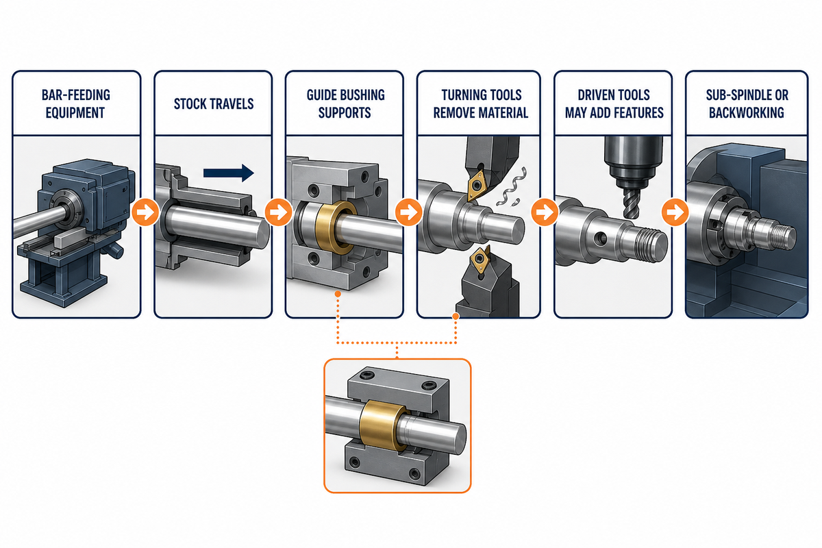
The defining mechanical idea is local support: the bar advances through the headstock while a guide bushing can support it near the tool. In conventional fixed-headstock turning, the stock is held by a chuck or collet and extends toward the cutting tool. In a traditional Swiss-type arrangement, the headstock moves the bar axially, and the guide bushing establishes a support point near the cut.
One basic sequence looks like this:
- Bar-feeding equipment presents stock to the main spindle and collet.
- Stock travels along the machine’s longitudinal axis as the sliding headstock moves.
- When used, a guide bushing supports the stock close to the active tool.
- Turning tools remove material while the headstock motion contributes to axial feed.
- Driven tools may add cross-holes, flats, slots, or other features if that machine and setup support them.
- A sub-spindle or backworking station may receive the part for features on the cut-off end.
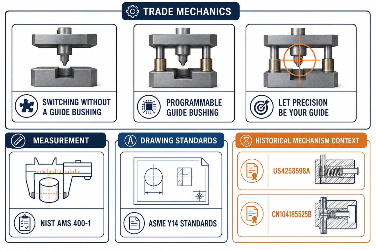
Local guide-bushing support reduces one source of instability: an excessive unsupported workpiece span at the cut. Historic guide-bushing patent drawings help document that mechanical relationship, but they do not prove a current machine configuration or supplier capability. Support doesn’t remove spindle error, axis error, tool deflection, driven-tool alignment, offset error, thermal movement, transfer error, or measurement uncertainty. Those remain part of the process system. This is why “made on a Swiss machine” isn’t a complete acceptance statement.
Terms that should not be collapsed into one claim
Sliding headstock describes how the main spindle and stock advance. Guide bushing describes a support interface near the cut. Collet grips the stock at the spindle. Sub-spindle can receive the component for cut-off-end work. Driven tooling adds rotating-tool operations on machines equipped and configured for them. These elements can appear in different combinations.
That vocabulary matters in a request for quotation. If the drawing needs a cross-hole and a back-end face feature, “Swiss machine” doesn’t prove that both will be produced in one clamping. Suppliers should name the proposed stations, transfer, and inspection state. Likewise, “single-cycle” shouldn’t be interpreted as “no handling or outside processing” unless the supplier’s route explicitly says so.
There’s also a difference between process potential and demonstrated process evidence. Short support distance may explain why a route is plausible. First-off records, a measurement-system definition, and stable production results are what make the claim testable. Keeping those two levels separate prevents a mechanical advantage from being stretched into a blanket quality guarantee.
Swiss-Type Lathe vs Conventional CNC Lathe
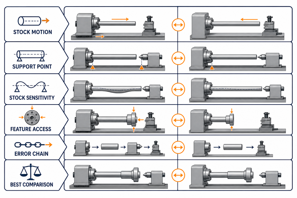
A Swiss-type lathe primarily differs in how the stock moves and where it can be supported; a conventional CNC lathe generally holds the stock at the spindle while tools move along the programmed axes. That support-zone distinction does not make either architecture universally more accurate. Choose the route whose workholding, tool access, error sources, and inspection plan match the part.
| Decision point | Swiss-type arrangement | Conventional turning arrangement | Why it matters |
|---|---|---|---|
| Stock motion | Sliding headstock advances the bar. | Stock is commonly fixed axially while the tool travels. | Changes programming, support, and feature sequencing. |
| Support point | Guide bushing can support close to the cut. | Chuck or collet supports the work from the spindle end. | Influences deflection risk on long, slender geometry. |
| Stock sensitivity | Bushing fit can make diameter consistency and straightness important. | No guide-bushing interface, though workholding still needs suitable stock. | Affects bar preparation and setup evidence. |
| Feature access | Machine-dependent driven tools and backworking can combine operations. | Live tooling and sub-spindles are also available on many configurations. | Actual axis and station evidence matters more than the category name. |
| Error chain | Includes bushing, sliding headstock, spindle, axes, tools, offsets, and transfer state. | Includes workholding, spindle, axes, tools, offsets, and transfer state. | Local support cannot prove the total capability of either system. |
| Best comparison | Documented setup against the complete drawing. | Documented setup against the complete drawing. | Compare evidence, not machine labels. |
How to Translate Common Swiss-Machining Language
Supplier pages may call the machining process Swiss turning, Swiss lathe machining, or work on a CNC Swiss machine. They may also refer to Swiss-type CNC lathes. These labels can describe a machine family, but none identifies the proposed bushing mode, axis and station plan, workholding, stock condition, or inspection route. The NIST on-machine measurement framework is a useful contrast because it separates the device, coordinate, environment, and recorded-result fields that a process label leaves open.
When buyers use Swiss machining as a search term, machining services pages often emphasize reduced deflection during machining and shorter machining time. Those are possible process effects, not guaranteed results. The advantages of Swiss machining must be tested against the actual machining work, especially the unsupported length at each cut and the operations that follow it.
A statement that a part is suitable for Swiss machining still needs a feature-by-feature route. Complex machining may combine turning, driven-tool work, transfer, and backworking, but the phrase “Swiss machining offers combined operations” does not show which ones a quoted setup includes. Swiss machines use different configurations, so buyers who rely on Swiss machining should also identify any secondary machining and the datum state after it.
A claim about Swiss equipment is incomplete unless it says which tool, spindle, or support mode a Swiss lathe uses. Likewise, “Swiss machining produces precision parts” is an outcome claim that needs drawing-linked evidence. Multi-axis CNC capability can expand access, and industries use Swiss systems for varied components, but where Swiss machines are used is less important than the controlled setup. Swiss machining becomes a defensible route only after the supplier documents the applicable configuration.
Swiss machining is commonly discussed through the applications of Swiss machining, yet application labels do not settle process control. Multi-axis machining may reduce handling, but a single machining cycle can still contain transfers, cut-off work, deburring, or other secondary machining operations. How Swiss lathes operate in the proposed mode matters more than the number of operations named in a brochure.
A supplier may describe machining operations in a single setup, but “single setup” needs a declared boundary. Many Swiss configurations can combine work, and Swiss machines often place several tools near the cutting zone; Swiss machines can perform only the operations supported by their actual stations and setup. The machining of intricate parts also depends on tooling for Swiss applications, while “Swiss machining stands for precision” remains marketing language until the evidence chain is defined.
Quality in Swiss machining should therefore be compared with the same discipline used for traditional CNC and traditional machining methods. Although Swiss technology has historical links to the Swiss watchmaking industry, a modern machine is still a lathe with a sliding headstock, workholding, offsets, tools, and measurement decisions. Machining small parts does not remove those error sources.
Terms such as “screw machine quality,” “machining solutions,” “Swiss automatic,” “Swiss platform,” and “multi-operation machining” are also supplier vocabulary rather than acceptance criteria. The benefits of Swiss operation must be separated from the quoted route. Micro machining and machining without a guide bushing pose different support questions; machining centers and multi-axis CNC lathes create other route options. Compare how a conventional lathe holds the workpiece, the stated machining steps, and where machining often changes datum, part state, or inspection responsibility.
Guide Bushing, Bushingless Mode, and the Real Support Question
A guide bushing is useful when the part needs support close to the active cut, but bushingless operation can be a better configuration when that support is unnecessary or when stock and process conditions make the bushing a liability. This is a conditional decision, not a permanent ranking of the two modes.
Trade coverage of convertible Swiss-type machines shows why the choice can’t be reduced to one length-to-diameter rule. Removing the guide-bushing housing can permit other stock forms, reduce sensitivity to the bushing-to-bar relationship, and change remnant or multi-pass behavior. Guide-bushing support can still be important when a slender section needs support near the cut. A historic guide-bushing mechanism supplies context for the support interface, not evidence of present adoption. Machine configuration, workholding, material, feature order, and the required result establish the practical boundary.
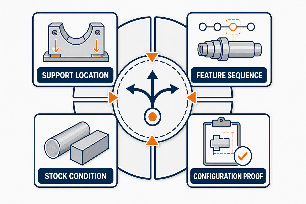
The Support-Zone Decision Dial
Created for this guide, the Support-Zone Decision Dial is a four-position discussion aid. It doesn’t calculate a machine setting or certify process feasibility. Move through the positions before assigning the route:
| Dial position | Evidence to examine | Decision consequence |
|---|---|---|
| 1. Support location | Where is the active cut relative to the collet or guide bushing, and what section remains unsupported? | If unknown, the route stays “investigate.” |
| 2. Feature sequence | Which diameters are turned before cross-work, backworking, retraction, or cut-off? | Sequence may change whether support remains effective. |
| 3. Stock condition | Grade, condition, form, diameter variation, straightness, roundness, and surface state. | Bushing fit and bar preparation become explicit setup inputs. |
| 4. Configuration proof | Actual machine mode, workholding, axis/station plan, tooling, thermal state, and inspection route. | Only a documented configuration can support the final route decision. |
Long-looking parts may have a stable cutting condition if each critical feature remains well supported. Shorter parts may still be awkward if cross-features, stock variation, or a retraction sequence conflict with the intended bushing mode. Use ratios as setup-specific evidence when a supplier provides them, not as universal law.
Which Parts Fit Swiss Machining, and Which Do Not?

Good candidates usually combine bar-fed geometry, a support-sensitive section, and a feature sequence that can be completed under a documented machine configuration. Diameter alone is a weak screen. Read the drawing together with unsupported length at each cut, cross-work, back-end access, material form, stock condition, inspection scope, and volume assumptions. The ASME Y14 standards hub provides drawing-language context, not route approval.
Search language can blur this review. Terms such as Swiss lathe, conventional lathe, CNC Swiss, and Swiss-type CNC identify broad process families, not finished capability records. Likewise, descriptions such as complex parts, intricate parts, slender parts, precision parts, precision machining, and precision manufacturing don’t define the geometry or acceptance method. Industry-specific drawings may demand tight tolerances and traceability, but the industry label can’t replace the controlled requirement and project-specific review.
| Screening result | Typical evidence pattern | Next action |
|---|---|---|
| Credible candidate | Bar-fed form; slender or support-sensitive features; accessible turning/cross/back features; controlled stock; repeat demand. | Request a configuration and inspection plan. |
| Investigate | Stock form varies; datum transfer is unclear; deep or intersecting features dominate; burr access is uncertain; thermal or measurement state is unstated. | Resolve the missing evidence before comparing offers. |
| Compare another route | Part is not naturally bar-fed; milling dominates; workholding or feature access conflicts with available stations; another route reduces transfers or evidence risk. | Use a milling versus turning route comparison and ask for both process plans. |
Prototype quantity doesn’t automatically disqualify the process, and high volume doesn’t automatically justify it. Setup, bar preparation, special tooling, inspection development, and secondary operations can dominate at low quantity. At higher quantity, the same investment may be distributed across more parts. Use the requested volume bands and route details for comparison rather than a generic minimum order.
Three drawing scenarios that change the screening result
Scenario one: a long turned stem with several nearby diameters. Support location is prominent, but the drawing still needs a feature-by-feature sequence. If the critical diameter is finished while well supported and can be inspected in its final state, the route may be credible. If a later operation changes the datum or surface, the earlier support advantage doesn’t settle final acceptance.
Scenario two: a short component dominated by cross-work. Nominal length may suggest that a guide bushing is unnecessary, while driven-tool access and backworking determine the efficient route. Buyers should compare the proposed axis and station plan with a conventional live-tool lathe or milling route. This is a configuration comparison, not a contest between process names.
Scenario three: a simple turned profile in uncertain stock. Geometry may look ideal, but bar straightness, diameter variation, surface condition, or form can complicate the bushing relationship. Credible responses identify the incoming-stock assumption, preparation responsibility, and inspection point. Without those details, a low unit price can conceal a different material basis.
Design Choices That Affect Stability and Cycle Strategy
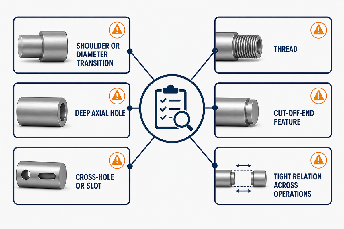
Feature geometry affects more than toolpath time; it can change support, tool access, chip evacuation, burr control, datum transfer, and the order in which the part must be machined. Because the preceding fit screen depends on stock and bushing relationships, public guidance rarely supports universal feature minimums across materials, machines, tools, and acceptance methods. Use the applicable ASME Y14 drawing language to define the requirement, then treat the following as route-review questions rather than design limits.
| Feature | Possible route risk | Question to resolve |
|---|---|---|
| Shoulder or diameter transition | Changes the supported section and may constrain retraction through a bushing. | Which diameters are cut before the support relationship changes? |
| Deep axial hole | Tool reach, chip evacuation, runout, and thermal load may control the plan. | What drilling sequence and verification method are proposed? |
| Cross-hole or slot | Driven-tool access, burr location, indexing, and feature relation matter. | Can the feature and its burr be completed and inspected in the planned station? |
| Thread | Runout, relief, tool access, and gauge state can affect acceptance. | Which standard, class, gauge method, and post-finish state apply? |
| Cut-off-end feature | May require sub-spindle transfer or a secondary setup. | Which datum survives transfer, and where is it re-established? |
| Tight relation across operations | Axis, offset, thermal, transfer, and measurement errors can accumulate. | What evidence separates local support from total process capability? |
Warm-up, changing spindle or driven-tool loads, machine interruptions, ambient shifts, and offset updates belong in the review when they can affect critical features. Even a stable guide-bushing relationship does not freeze the rest of the machine. Ask how first-off approval, restart approval, and in-process checks handle those changing states.
During route review, follow one critical characteristic from incoming bar through the supported cut, any driven-tool operation, cut-off, sub-spindle transfer, deburring, finishing, conditioning, measurement, report generation, and final disposition, because a process can look stable at the guide bushing yet still lose comparability when an offset changes, a datum is re-established, a burr is removed, a surface is treated, a different instrument is used, or an acceptance decision applies a different rule near the specification boundary.
Material and Bar-Stock Conditions Are Process Inputs
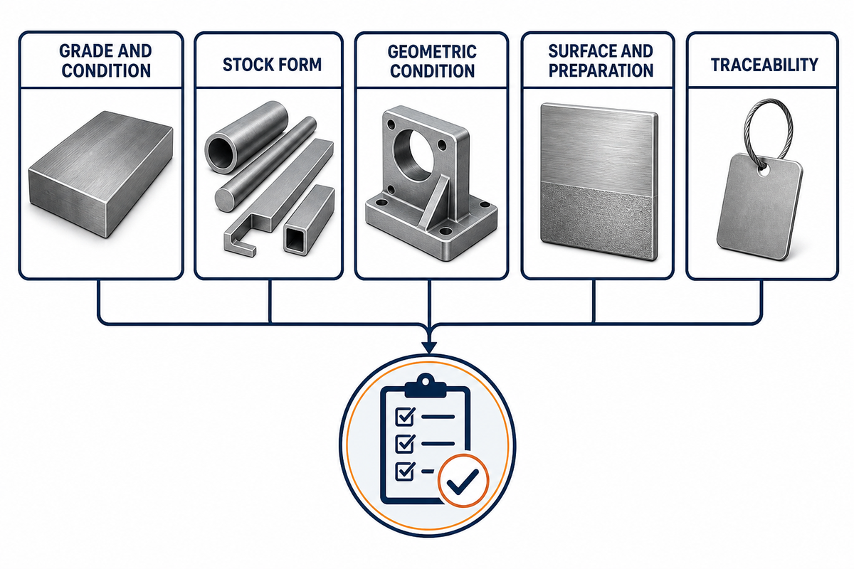
A material family name isn’t enough to define a Swiss-machining setup. Requirements should identify grade, condition, permitted substitutions, stock form, certification needs, and any known straightness, roundness, diameter, or surface constraints. Those details affect the guide-bushing interface, cutting behavior, tooling, chip control, and inspection.
“Stainless steel,” for example, can conceal differences in grade, supply condition, machinability, corrosion requirement, and post-machining processing. Similar differences apply to carbon steels, alloy steels, aluminum alloys, nickel-based materials, and plastics. Use the site’s broader CNC material selection guide for alloy-selection context; keep this Swiss-specific record focused on what the setup needs to know about the incoming bar.
Guide-bushing operation can require a controlled relationship between the bar and bushing. That doesn’t mean every job needs centerless-ground stock, or that bushingless operation accepts any stock. It means the supplier should disclose the assumed stock condition and any preparation step in the process plan and quote. The NIST measurement-use-case report separately identifies material and environmental conditions as fields worth recording. When the purchase specification allows substitution, state who may approve it and which functional or inspection evidence must remain unchanged.
| Input | What to disclose | Why it changes the review |
|---|---|---|
| Grade and condition | Specification, temper or processing condition, and substitution rule. | Affects cutting response, tooling, downstream processing, and functional evidence. |
| Stock form | Round, hex, extrusion, tube, or another supplied form. | Can change workholding and guide-bushing feasibility. |
| Geometric condition | Applicable diameter, straightness, and roundness evidence. | Defines the assumed relationship between stock and support system. |
| Surface and preparation | As-drawn, ground, peeled, coated, or prepared by the supplier. | Changes friction, fit, yield, cost, and responsibility. |
| Traceability | Certificate, heat/lot link, segregation, and retention requirements. | Determines whether the delivered record can be tied to the accepted material. |
Tolerance, Surface Finish, and Inspection Must Share One State

A tolerance becomes testable only when the feature, datum scheme, part state, measurement method, and acceptance rule are defined together. That shared material-and-stock definition must carry into inspection: tight numbers on drawings don’t prove that every supplier will measure the same feature in the same way or reach the same conformity decision.
NIST’s on-machine measurement work separates calibrated artifacts, probe identity, coordinate offsets, repeatability, controlled measurement devices, material and environmental conditions, and recorded results. That’s a useful warning for procurement: “inspection included” isn’t a complete scope. Both parties also need to agree how results are interpreted, especially when uncertainty or guard-banding can affect acceptance near a specification limit.
| Evidence category | Record it as | Risk if omitted |
|---|---|---|
| Feature and datum | Drawing revision, characteristic ID, datum references. | Different interpretations of the measurand. |
| Part state | In-machine, first-off, post-cutoff, post-finish, or final. | Results from different operation states are compared as equivalent. |
| Thermal/conditioning state | Applicable conditioning, warm-up, environment, and timing. | Thermal history is mistaken for stable capability. |
| Equipment and traceability | Instrument type/ID, calibration or reference basis, fixture, program. | Apparent agreement cannot be traced or reproduced. |
| Sampling and record | Frequency, sample location, result format, retention. | A pass claim has no defined population or evidence trail. |
| Acceptance rule | Specification limit plus agreed uncertainty or capability decision rule and disposition owner. | Two valid measurements can lead to inconsistent accept/reject decisions. |
| Surface state | As-machined, deburred, cleaned, treated, coated, or final state. | Finish and edge changes are compared across different states. |
| Report identity | Part/lot, revision, date, program, operator or system, and result linkage. | The record cannot be tied to the accepted product. |
| Change trigger | Events that require revalidation, reapproval, or a revised measurement plan. | Changed tooling, stock, offsets, or route can inherit stale evidence. |
ASME Y14 standards provide drawing-language context, but a standard title or edition doesn’t prove that a particular setup can hold a requirement. For more on datum transfer and measurement planning, see the turning design and inspection guide. Supplier evidence still needs to refer to the controlled drawing and agreed inspection state.
Cost and Lead Time Depend on the Part Route, Not the Process Label
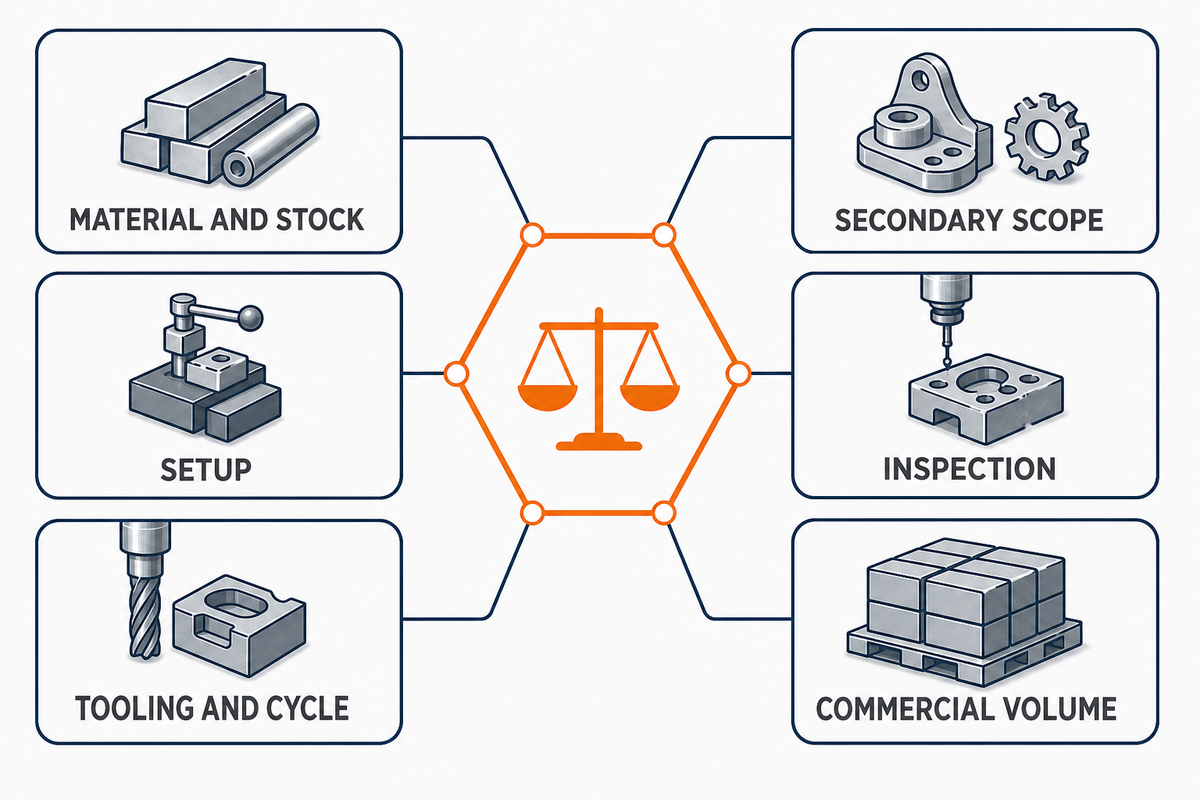
The process family influences feasible routes, but “Swiss machining” alone can’t establish a comparable price or lead time. Quote assumptions may differ across bar preparation, setup, tool development, cycle strategy, unattended running, inspection, secondary work, finishing, scrap risk, packaging, and volume. Unless those assumptions are visible, two totals may describe different scopes.
- Material and stock: grade, condition, form, certification, preparation, and yield.
- Setup: workholding, guide-bushing mode, bar feeder, offsets, first-off approval, and restart controls.
- Tooling and cycle: standard or special tools, tool life assumptions, operation overlap, and bottleneck operation.
- Secondary scope: deburring, cleaning, heat treatment, coating, grinding, or separate machining.
- Inspection: characteristic list, equipment, sampling, reports, capability evidence, and traceability.
- Commercial volume: prototype quantity, release sizes, annual estimate, and forecast confidence.
This research didn’t establish a universal hourly rate, savings percentage, lead time, or minimum order quantity. Practitioner estimates can illustrate that machine, labor, utilities, and consumables exist, but they aren’t published market rates and aren’t used here. Zhenling’s dedicated CNC machining cost guide covers broader cost planning; this guide’s role is to expose Swiss-specific assumptions.
How to Prepare a Supplier-Comparable Evidence Package
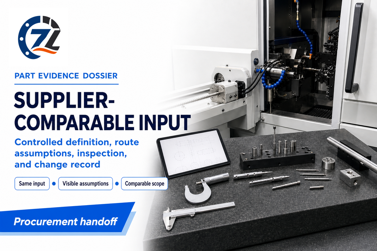
Supplier responses become comparable when each supplier receives the same controlled part record and returns assumptions against the same seven evidence fields. Because cost and lead-time comparisons depend on declared assumptions, the format below is an editorial procurement aid, not an industry standard, a feasibility approval, or a substitute for drawing review. Its measurement fields are informed by the categories in NIST AMS 400-1, while the seven-field dossier itself is original to this guide.
The 7-Input Part Evidence Dossier
- Controlled definition: drawing and model revision, units, conflict-resolution rule, and change owner.
- Material and stock: exact grade and condition, form, certification, substitution limits, and any bar-condition requirements.
- Feature-criticality record: function-critical characteristics, datum relationships, cross-work, backworking, burr-sensitive locations, and cosmetic boundaries.
- Volume record: prototype quantity, release bands, annual estimate, and demand uncertainty, not one inflated headline volume.
- Process-state assumptions: proposed machine mode, operation sequence, secondary work, finishing state, thermal/warm-up controls, and restart handling.
- Inspection and decision rule: measurement state, equipment, sampling, traceability, report format, uncertainty or capability decision rule, and nonconformance owner.
- Approval and change record: sample or first-article expectations, deviation route, packaging, document retention, and conditions that require reapproval.
Ask each supplier to identify exclusions and assumptions next to these fields. A “complete” response doesn’t prove capability, but it reveals whether price, timing, and inspection scope refer to the same problem. It also makes a conventional-turning alternative visible when that route is more defensible.
Normalize responses before comparing the totals
Start with scope, not price. Mark whether each response includes the same material source and condition, bar preparation, special tooling, sample approval, production inspection, secondary operations, finishing, packaging, and documentation. Put an unresolved item in an “open” column instead of silently assigning it a favorable assumption.
Next, compare the proposed route. One supplier may combine turning, cross-work, and backworking in the proposed configuration. Another may use a separate operation because it improves access or inspection. Fewer operations aren’t automatically better if the combined route creates an uncontrolled datum transfer, burr, or measurement problem. The relevant question is which response describes and controls its route most clearly against the functional requirements.
Finally, compare evidence timing. Record what’s due before production approval, what accompanies each shipment or lot, and what’s available only on request. A first-article record, an in-process check, and a final report answer different questions. If a critical characteristic has no named evidence point or disposition owner, the offer remains technically open even when the commercial total is complete.
For procurement teams, the most revealing comparison is often the exception path: ask what happens when incoming stock differs from the quoted assumption, a tool change shifts a critical feature, first-off and final inspection disagree, a finish alters the measured surface, or a release quantity changes, then require the response to identify who reviews the event, which record controls disposition, and whether production can continue.
Once the dossier is stable, it can support a commercial handoff. Zhenling Metal can review the controlled requirements through its Swiss machining drawing and production review. This article doesn’t claim that Zhenling owns a particular Swiss-type machine, guide-bushing system, or machine configuration; those facts should be confirmed during the project-specific review.
“Compare the controlled route and its evidence, not the process label alone.”
What Is Actually Changing in Swiss Machining?
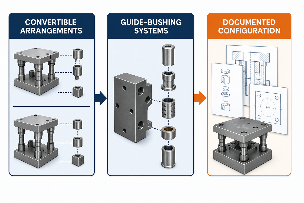
The defensible current story is technical configuration change, not a proven market-growth rate. Once the evidence package names the proposed configuration, trade publications provide context for alternatives such as convertible guide-bushing/bushingless arrangements and guide-bushing systems whose pressure or operating behavior can be adjusted for particular applications. A guide-bushing patent record can document an attributed mechanism, but not present market adoption. These developments can change setup choices and the questions a buyer should ask.
The buyer implication is modest but useful: do not assume “Swiss-type” means one fixed architecture. Ask which mode and support system the supplier proposes, which stock condition it assumes, and which features are produced before and after transfer. A newer option is not automatically better; it expands the configuration space that must be documented.
This run’s exact-keyword history did not support a reliable demand trend, and no governed source established a market growth rate. Old guide-bushing patents can document historical mechanisms or ownership, but they do not prove current adoption. The article therefore makes no forecast and attributes no Swiss-specific invention or equipment ownership to Zhenling.
Key takeaway
A credible Swiss-machining decision joins support-zone mechanics to the actual feature sequence, stock condition, machine state, and inspection decision rule. If any link is unknown, keep the route at “investigate.”
Swiss Machining FAQ
What is Swiss-style machining?
Swiss-style machining is a CNC turning method that uses a sliding headstock to feed bar stock through the cutting zone. In the traditional configuration, a guide bushing supports the bar close to the tool. Modern Swiss-type machines may also offer bushingless modes, driven tools, and backworking when the specific model and setup provide them. The proposed configuration, rather than the category name, should identify which operations and support relationships apply to the drawing.
Why is it called Swiss machining?
The name traces to a turning approach developed for small, slender components in the Swiss watchmaking industry. Today, “Swiss-type” describes a machine architecture and process family, not the country where the machine or part is made. Historic guide-bushing patent material documents a mechanism and attribution, not a modern supplier’s accuracy or origin.
Is Swiss machining the same as Swiss screw machining?
The terms often overlap in commercial use. “Swiss screw machining” reflects automatic production of small turned components; “Swiss CNC machining” emphasizes computer control and possible driven tools, sub-spindles, or combined operations. Confirm the proposed configuration for the drawing instead of relying on either label.
What size parts suit Swiss machining?
There’s no universal size cutoff that makes a part suitable. Review documented bar capacity together with unsupported length at each cut, bushing mode, feature sequence, tool access, stock form, and inspection. Diameter is only the envelope question. A short component dominated by cross-work can be harder to route than a longer turned stem, while a slender feature may become credible when it stays supported during its critical cut. Stock condition can narrow the choice further.
What are the disadvantages or limits of Swiss machining?
Potential limits include stock sensitivity, setup and tooling effort, remnant, feature-access constraints, thermal and offset control, and inspection complexity. Another turning or milling route may be easier to control when preparation or transfers outweigh close support for a particular part.
Is Swiss machining good for prototypes?
Swiss machining can suit prototypes, especially when prototype geometry needs the same support or combined-operation strategy expected in production. It may be uneconomic when setup, bar preparation, special tooling, or inspection development dominates a very small quantity. A prototype can also reveal transfer, burr, stock, and measurement issues before release quantities rise. Compare a documented prototype route with conventional turning or milling, and state which evidence must carry forward into production, instead of using quantity alone.
References & Sources
- Production Machining, Switching to Swiss Without a Guide Bushing: configuration-specific support, stock, remnant, and pass-sequence discussion.
- Production Machining, Consider a Programmable Guide Bushing: guide-bushing configuration development.
- Cutting Tool Engineering, Let Precision Be Your Guide: guide-bushing mechanics and application conditions.
- NIST AMS 400-1, On-Machine Measurement Use Cases and Information for Machining Operations: measurement equipment, calibration, coordinate, repeatability, traceability, and thermal-compensation information.
- ASME Y14 Standards Hub: drawing-language standard titles and editions; not supplier capability proof.
- US4258598A, Guide Bushing Patent Record: historical mechanism and attribution context only.
- CN104185525B, Guide-Bushing Patent Record: attributed mechanism context; not evidence of current adoption or Zhenling ownership.
Prepared as an educational guide for Zhenling Metal. It doesn’t replace drawing review, machine-specific feasibility analysis, an inspection agreement, or a project quotation.