
Get in touch with Zhenling Company

By CYH · Updated October 2026
Micro CNC Machining specializes in features whose small size makes edge effects and runout especially important. For example, a burr on a smaller component can render the part completely unusable, whereas a larger component may be usable after burr removal. Because of this, the feature and the way the component will be cut and inspected are important for ensuring reliability.
This guide will explain the reasoning behind the engineering decisions. Why can reducing feed make cutting worse? How do we find usable reach? When is the lowest machining time not the best for cost per accepted part?
Quick engineering reference
- Micro-scale behavior depends on the relationship between the chip, cutting edge and material structure.
- Drawing tolerance, instrument resolution and measurement uncertainty describe different things.
- Judge a process by finished, accepted features after deburring and cleaning.
What Micro CNC Machining Changes at Small Scale
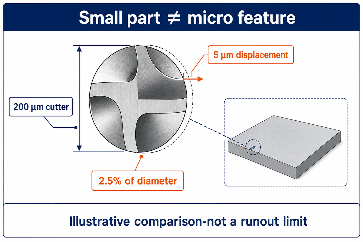
Micro machining changes the balance between the cutting tool and the material. Edge rounding, grain structure and a small amount of displacement can become substantial relative to the feature. For precision machining at this scale, complete control of the cutting and measuring system is essential even if the machine layout resembles a larger CNC mill.
How does micro CNC machining work?
Computer numerical control (CNC) removes material from a workpiece using a program to control the movement of a cutter. While the program defines motion, the actual cut also reflects the tool geometry, spindle behavior, stiffness of the fixture, and response of the workpiece material. These effects can become substantial relative to chip thickness or the permitted variation in a feature. This leads to CNC machining becoming very difficult.
A small part and a micro feature aren’t interchangeable. A large plate can contain a small channel, and a connector of small size can have numerous turned surfaces. Determine the important feature of the part before selecting tolerance for every surface.
Specifications of a high-precision CNC require stated measurement conditions. High precision on a positioning display says little about a cut made with an unstable holder; thermal stability and the measurement setup also have to suit the tolerance.
The 2021 review by O’Toole, Kang and Fang explains why simply scaling down standard machining models misses edge and material effects. An advanced CNC machine still needs a toolholder, tool path and inspection method suited to the feature. Axis resolution alone can’t settle that question.
For a 200 µm cutter, a 5 µm displacement would represent 2.5% of its diameter. That comparison in dimensions explains why a small absolute error requires consideration; it isn’t a permissible runout limit. Reserve tight tolerances for the surfaces that control assembly or function.
Minimum Chip Thickness, Runout and Tool Rigidity
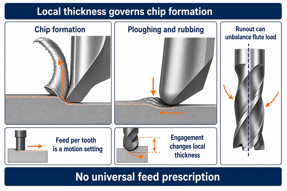
Minimum chip thickness is the local cutting thickness below which material may deform and plough instead of consistently forming a chip. Feed per tooth governs this thickness, but both engagement and runout affect it throughout the tool’s rotation. In fact, decreasing the feed may increase rubbing. A fragile cutter can be easily damaged from rubbing.
Two experiments show why a universal edge-radius multiplier is unreliable. De Oliveira and colleagues’ AISI 1045 steel study reported a minimum uncut chip thickness of 22–36% of the cutting edge radius. Rezaei, Sadeghi and Budak’s Ti-6Al-4V study reported 0.15–0.49 times the edge radius across its tested conditions. Converted to percentages, the latter spans 15–49%; the ranges overlap but have different boundaries.
Neither range is a feed prescription for an unfamiliar tool. Minimum chip thickness is a local geometrical condition. Commanded feed per tooth is a motion setting; radial engagement and the cutting edge trajectory determine the instantaneous thickness. The steel study also showed that attaining chip formation didn’t always lead to the best surface roughness.
Specific cutting energy is defined as the energy per unit volume removed during cutting. It is therefore a different quantity from the total cutting force in a particular case. While reading the micro-milling review, bear in mind this distinction when interpreting the size effect.
Calculate speed, then check the cutting regime
MIT’s spindle-speed equation connects rotational speed, surface speed, and tool circumference. In metric units, the equation is n = 1000 × Vc ÷ (π × D), where Vc is in m/min, D in mm and n is in rpm. Table feed follows Vf = fz × z × n, where feed per tooth fz is in mm/tooth and z is the number of cutting teeth.
Example: A process engineer considers a 0.2 mm, two-flute end mill at an assumed cutting speed of 20 m/min. Calculations show this would give a spindle speed of 1000 × 20 ÷ (π × 0.2) = 31,831 rpm. Assuming a feed of 0.002 mm/tooth, the table feed would be 0.002 × 2 × 31,831 = 127.3 mm/min. A 20,000 rpm spindle would achieve a surface speed of 12.57 m/min and, with feed per tooth unchanged, a table feed of 80 mm/min. The process engineer can now make a clear comparison between cutting conditions. Lower speed decisions change surface speed. Chip load changes the feed commanded to the table. Choices made must take into account tool-chip interaction and material behavior.
Rigidity is also essential. Longer reach increases the risk of deflection, and runout can also cause one flute to carry more load than the other. High-speed spindles don’t alleviate those issues. In a Cutting Tool Engineering interview, Steve Bryan of Bryan Machine Service said the extended system from the spindle increases vibration.
“The further you get away from the machine spindle, the more vibration you get.”
To achieve 20 m/min, a 0.2 mm tool would need to run at approximately 31,831 rpm, based on circular circumference alone. Decreasing the speed to 20,000 rpm would reduce the surface speed to 12.57 m/min. Connection: Speed and feed per tooth and engagement need to be kept connected when comparing equipment; specifying rpm by itself doesn’t determine a process.
Micro Milling vs Micro EDM, Turning and Laser Processes
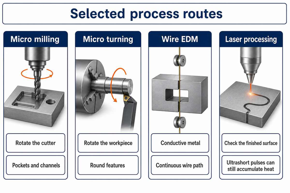
Choose a micro-machining process based on the geometry it can reach, the material it can remove and the surface it leaves behind. Mechanical cutting can be achieved through milling and turning; EDM is an option if the material is electrically conductive; and laser processing is a route to take based on the material’s response to the energy source. No process dominates all features to be compared.
The feature families below are offered as starting points for discussions on processes. They describe how a given process can create a feature and how that process can fail, and aren’t meant to be advertisements for process minimums.
| Feature family | Route to consider | First deciding factor | Engineering consequence |
|---|---|---|---|
| Open shallow pocket | Micro milling | Cutter access and chip escape | Keep a clear path for chips; an open top alone does not prevent recutting. |
| Deep narrow slot | Micro milling or EDM | Reach, cutting length and evacuation | Separate the depth that must be reached from the edge length engaged at once. |
| Blind shaped cavity | Milling or sinker EDM | Corner shape and electrode access | A rotating cutter leaves a radius; a shaped electrode introduces wear and discharge-gap allowance. |
| Through-profile in conductive metal | Wire EDM | A continuous wire path | Wire access and workholding must remain possible after the profile separates. |
| Slender round shaft | Micro-turning or Swiss-type turning | Support near the cut | Long unsupported stock can deflect even when the commanded position is correct. |
| Small drilled hole | Micro drilling | Entry, depth and chip exit | A drill can reach the target depth while still producing an unacceptable exit burr. |
| Thin web or wall | Supported micro milling | Clamping and cutting load | Support the feature during the cut and measure it after release. |
| Microfluidic channel | Milling or suitable laser route | Channel form and edge cleanliness | A burr occupies flow space; a bright channel floor does not establish the cross-section. |
| Fine surface texture | Laser processing or appropriate cutting route | Functional texture and thermal effects | Specify the texture being measured; lower average roughness is not a substitute for the required pattern. |
Nafi and Jahan’s EDM review distinguishes shaped die-sinking electrodes from wire electrodes and describes thermally modified surface layers. Hard conductive tool steel may be a good EDM candidate, but electrode wear, flushing and the final surface still govern the route.
Micro milling vs micro turning: what changes?
Micro milling rotates the cutter to create features such as pockets and channels; micro-turning rotates the workpiece to create round features such as a shaft. Decide which rotation supports the critical feature best. A part that contains both may require combined operations with careful attention to the datum transfer between them.
Our milling-versus-turning guide extends the geometrical comparison at the part level.
Laser processing also has particular surface requirements. Bauer and colleagues’ 2015 metal-ablation experiment showed that ultrashort pulses can still accumulate heat under the average-power and scanning conditions tested. Hence, “ultrashort” can’t be considered as a general case to approve the finished surface.
Design Around Micro End Mills and Micro Drill Bits
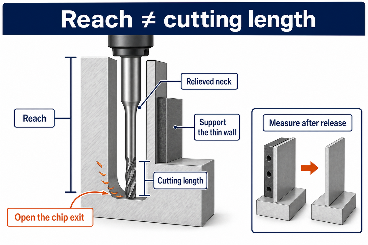
Design micro features around access to the cutting edge and support during machining. A cutting tool has to reach a feature, clear surrounding geometry and evacuate chips. There are different trade-offs to be made regarding length, reach and diameter, and one dimension can’t stand in for the entire tool.
Reach determines where the tool can extend; cutting length describes how much of the tool is comprised of a cutting edge. A relieved neck can pass alongside a wall and not cut it. Taking multiple shallow passes with a short cutting edge can impose a different load from engaging the full reach in one deep pass.
In the case of complex geometries, determine which internal geometries remain inaccessible after assembly. Design features that can be drawn may not provide a viable cutting or inspection path.
The micro-milling review connects tool geometry and stiffness with the cutting response. In the 5-axis machining guide, for more broad machine access decisions, the role of the tool’s orientation is described. After adjusting orientation, check the reach and clearance limits of the tool.
Imagine a channel 0.5 mm wide and 4 mm deep with a thin wall. The drawing provides access from the top but no access from the sides. A long-reach tool may physically access the bottom of the channel but, again, there’s little space for chip removal. The designer has a few options: opening an end, reducing the depth, moving the channel away from the wall, or splitting the feature through an assembly. If the channel remains the same, process planning must consider tool engagement and chip removal throughout the full depth of the feature. Increasing clamp force isn’t a free improvement if it bends the wall. The real improvement in design is the removal of the limiting mechanism.
The 2021 exit-burr study associates burr formation with loss of support stiffness of the workpiece as the cutting edge exits the workpiece. Because of this, we should consider the geometry of the exiting cut before we perform the operation. Micro drill bits face a similar problem when planning the entry and exit edges of the hole. The exiting edge may not be accessible or may require burr removal.
We need to design corner radii compatible with the cutter, keep unsupported reach as short as possible and define which edges are to be left sharp after final finishing. The design-for-machining guide discusses other drawing choices; the micro-scale addition is to analyze the smallest edge and chip path precisely.
| Limiting feature | Change to consider | Verification after the change |
|---|---|---|
| Deep micro hole | Shorten the small-diameter section using a larger access bore where function permits. | Check the remaining small bore and transition, not just the accessible opening. |
| Thin wall | Move the cut toward supported material or change the clamping arrangement. | Measure the released wall in its specified state. |
| Closed narrow channel | Open an end or divide the geometry across an assembly if function permits. | Inspect channel form, joining alignment and edge condition. |
| Inaccessible datum | Add a usable reference surface while preserving the functional datum relationship. | Demonstrate how the inspection setup locates the finished feature. |
A 0.5 mm channel with a depth of 4 mm has an 8:1 depth-to-width ratio. This ratio describes the feature, not a condition allowing a cut to be made. Opening the chip exit or improving wall support may be more effective than specifying a smaller cutter since a smaller diameter may also result in lower tool stiffness.
Micro Machining Aluminum, Steel and Other Materials
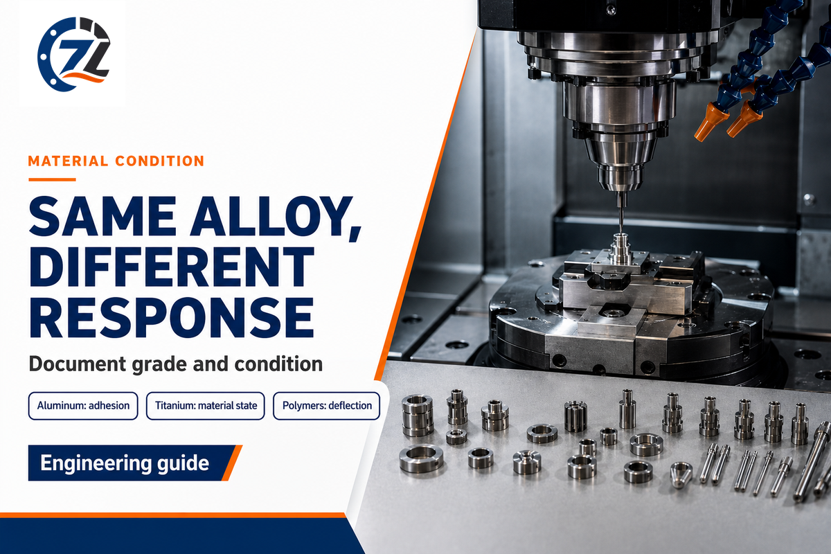
When working with micro components, the material grade and its condition are to be taken into consideration when selecting a material. Adhesion, work hardening, and local microstructure can influence cutting at small scales. A feed that works with one alloy or heat treatment can give a different burr and/or produce different forces and wear with a second alloy or heat treatment, even if the nominal geometry is the same.
Can metals and plastics both be micro-machined?
Yes. Metals and plastics can both be micro-machined with appropriate cutting tools and support. Their limiting mechanisms are also different: a ductile metal can smear and/or form a burr; a compliant plastic can deflect under clamping and cutting. Material-specific tooling and a defined measurement state matter more than the micro label.
Adhesion and chip evacuation are critical for aluminum and copper. Heat, hardening and wear behavior are issues with stainless steel and titanium. Polymers, like PTFE, may also distort under clamping and thermal conditions. Functional material requirements determine selection; ease of cutting doesn’t determine selection of an implant material or aerospace alloy.
For micro-surgical tools, identify the functional edge and required finished material condition before optimizing the cut. A machining trial is done to assess the behavior of the material for manufacturing and not to determine the suitability of the material for a medical use.
For compliant polymer parts, refer to the PTFE machining guide for material-specific set up questions. The behavior described below was observed in a titanium experiment.
An example from Attanasio and colleagues’ 2013 Ti6Al4V experiment is useful here. Four micro structures were cut with 200 µm end mills. In those tests fully lamellar specimens produced lower cutting forces and reduced tool wear. A key point is to record the condition of the material when comparing lots, rather than using the alloy name as the description.
Heat treatment serves the part’s final function. For this reason, changing the heat treatment merely to gain better machinability could cause a whole other set of problems. Our CNC material selection guide provides a much wider comparison of materials.
Titanium micro structures, all with the Ti6Al4V designation, exhibited various responses to cutting with a 200 µm cutter. Along with tool and engagement settings, material condition should be documented. When results vary between lots, check that variable first before concluding that the machine has lost precision.
Why Micro End Mills Break: Diagnose Before Slowing Down
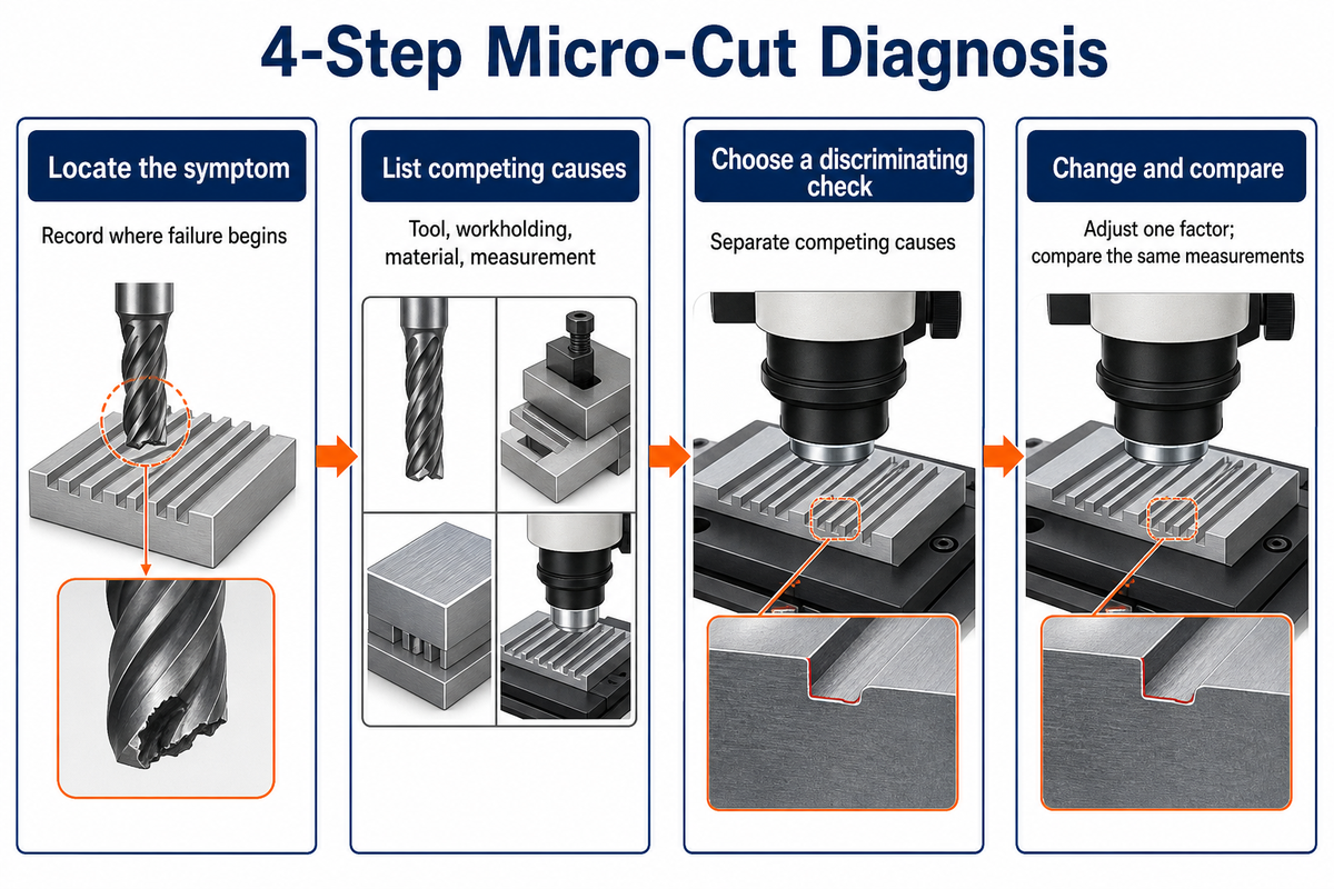
Micro end mills break due to localized overloading, wear, or instability that’s beyond the capacity of the tool. There are other variables at play. Useful diagnosis connects the failure location with surface evidence to competing causes and then alters one controlled variable to see how it affects the tool and part being studied.
4-Step Micro-Cut Diagnosis
The 4-Step Micro-Cut Diagnosis method connects symptoms to competing causes and uses a discriminating check and a controlled corrective action.
- Locate the symptom. Record where breakage, burr growth or dimensional drift begins.
- List competing causes. Include tool, workholding, material and measurement effects.
- Choose a discriminating check. Use an observation that separates those causes.
- Change and compare. Adjust one factor and compare the same acceptance measurements.
The matrix applies that sequence to various micro-part problems. It’s a diagnostic tool, so each action is tied to an observation rather than a universal feed correction.
| Observed symptom | Competing causes | Discriminating check | Action and boundary |
|---|---|---|---|
| Burrs grow after feed is reduced | Ploughing, worn edge or poor exit support | Compare edge condition and chip formation with engagement held constant | Restore a supported cutting regime; do not keep halving feed automatically. |
| One flute wears faster | Runout or uneven tooth engagement | Measure the rotating tool near the cutting edge | Clean and reseat the holder, then remeasure before changing the program. |
| Breakage repeats at the bottom of a slot | Chip packing, excessive engagement or lost clearance | Inspect chip exit and the depth at which failure begins | Revise evacuation and engagement; a slower cycle can still recut trapped chips. |
| Slot width changes with cutting direction | Tool or workpiece deflection | Compare opposite passes and released-part measurements | Reduce unsupported reach or improve support before compensating the path. |
| A hole meets diameter but blocks flow | Exit burr, debris or an incomplete opening | Inspect both ends and the functional passage | Control the exit edge and cleaning method, then measure again. |
| An optical slot appears narrower than the cutter | Burr or threshold-related edge detection | Examine the profile and chosen measurement edge | Resolve the edge definition before changing cutter compensation. |
| Surface finish changes between material lots | Microstructure, hardness or inclusion differences | Compare material condition as well as grade | Keep the specified material state consistent; do not alter heat treatment solely for easier cutting. |
| Parts pass while clamped but fail after release | Elastic fixture distortion | Repeat measurement in the defined free state | Change support and clamping force; extra clamping can worsen the result. |
| A monitoring alarm disagrees with inspection | Unvalidated sensor/model transfer | Compare the alarm with actual wear and part measurements | Revalidate the signal for the material, tool and engagement before automatic intervention. |
The mechanisms draw on the micro-milling review and the exit-burr experiment. Modern Machine Shop’s interview with Harvey Performance’s Jeff Davis also explains how tool replacement and instability can erase the benefit of a faster programmed cycle.
The more complete CNC milling process guide provides broader context. The checks address the micro scale; apply them to the particular feature that’s failing.
Regarding the assumed 0.2 mm, two-flute example, decreasing the table feed from 127.3 mm/min to 63.7 mm/min at a spindle speed of 31,831 rpm reduces the commanded feed per tooth from 2 µm to approximately 1 µm. Reducing feed per tooth to 1 µm may increase ploughing, depending on the local cutting regime.
Micro Part Inspection: Separate Tolerance from Resolution
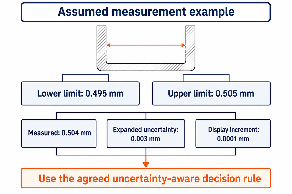
Micro-part inspection must assess the specified feature with uncertainty small enough for the agreed acceptance decision. Instrument resolution describes the display or measurement increment, rather than overall measurement uncertainty. Edge interpretation, sampling, probe size, alignment, temperature and fixturing affect the result; therefore, a high resolution instrument doesn’t necessarily establish conformity.
How accurate is CNC micro-machining?
Accuracy is a feature-specific result established by measurements, rather than a single number attached to CNC machining. State dimension, datum and the tolerance, and then evaluate process and measurement uncertainty. The same part may require various measurement methods for a bore, a thin wall and the floor of an inaccessible channel.
The document NIST’s dimensional-metrology guidance connects traceability with an unbroken chain of comparisons and their uncertainties. ISO 14253-1:2017 covers conformity decisions when measurement uncertainty may be present, e.g. when measured values are near the specification limits. The public listing states the 2017 version is the current one, after confirmation in 2023.
Engineering note
Example: a 0.500 ± 0.005 mm feature has limits of 0.495–0.505 mm. A displayed result of 0.504 mm is only 0.001 mm below the upper limit. If the stated expanded measurement uncertainty is 0.003 mm, the acceptance decision needs the agreed uncertainty-aware rule; display resolution alone can’t resolve it.
A quality engineer gets the result 0.504 mm on a channel. The display resolves 0.0001 mm, and at first glance, that looks much finer than the tolerance. However, reported expanded uncertainty is 0.003 mm, and the optical edge changes with the illumination. Before accepting the part, the engineer checks the defined edge, measurement setup and agreed decision rule. Deburring is part of the finished-part sequence; hence the result has to represent the channel after deburring. Doing the same biased edge selection multiple times wouldn’t remove bias. A measurement method that consistently identifies the real feature boundary would be a better method.
That concern has an experimental counterpart. Abeni and colleagues’ 2024 study reported a nominal 800 µm tool measured at 789 ± 2 µm and found burr-related difficulty in optical slot-width measurements. NIST’s aperture measurement study identifies overall-form sampling and finite-probe filtering as additional uncertainty contributors. Optical methods and a CMM therefore have different access and sampling constraints.
For a 0.500 ± 0.005 mm feature, the total tolerance width is 0.010 mm. A 0.0001 mm display increment is just one part of the measurement system. Define the finished edge, sampling and acceptance rules before accepting a measurement near either spec limit.
Micro Machining Cost: Pay for Good Parts, Not Just Cycles
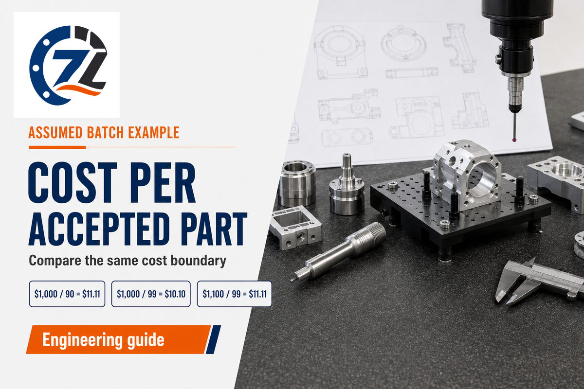
To compare micro machining cost, consider how many parts are accepted in the batch and what costs are associated with that batch. The advantage of a short cutting cycle may be lost due to tool replacement, deburring, inspection and scrap. The comparison keeps the cost boundaries consistent and includes other costs associated with any process improvement.
The American Society for Quality’s cost-of-quality framework separates prevention, appraisal and failure costs. Inspection is appraisal, while scrap and rework are failure costs, internally. Analysis of these costs may help to understand why machining time alone isn’t sufficient.
Accepted-Part Cost Example
The Accepted-Part Cost Example divides the included batch cost by accepted output to show how yield changes an operational comparison.
Assumed Inputs: Setup costs, $300, machining costs, $5/started part, and $2/started part inspection costs. For 100 starts, the total included expense is $300 + 100 × ($5 + $2) = $1,000. With 90 accepted parts, the result is $11.11 per accepted part, and with 99 accepted parts the result is $10.10 per accepted part. Holding the expense fixed isolates the yield effect. If the improvement adds $100 of prevention, process or other costs, the second result becomes $1,100 ÷ 99 = $11.11. Relevant rework and other costs that have been omitted should be included prior to effecting the comparison. This is a defined comparison of an operational batch. Inventory accounting and supplier’s selling price use their own cost boundaries.
The CNC machining cost guide covers broader cost drivers. For a micro feature, include handling and inspection steps that remain after the cutter stops.
Move from a Prototype to Repeatable Micro Components
Repeatable micro components require a stable sequence from material condition through cutting, finishing and measurement. A successful prototype shows that a part has been made under specific conditions. Production needs control of tool variation across the run and acceptance measurements that represent the finished feature.
Define the material condition, tool and holder setup, cutting parameters, deburring, and inspection state together. Compare parts across tool life and after replacement. Automation can’t compensate for an undefined datum or a measurement that follows the wrong edge.
In process control, variation should be linked to a particular cause. In CNC precision machining, the change in size after tool replacement requires an investigation different from random damage caused by handling.
Work is underway to expand monitoring. In Abu, Huo and Liu’s March 2026 study, researchers combined acoustic emission and force signals with 0.9 mm diamond-coated tools in the micro-milling of glass and silicon. They call for incorporating the controllers and extending the work to other brittle materials. Working with metals requires additional verification, and a lab signal model doesn’t guarantee a ready to use process control.
Key takeaway
A 200 µm cutter, a micron-scale tolerance and a fine display resolution describe different parts of the process. Reliable micro machining connects feature geometry, cutting behavior and the measurement used to accept the finished part.
When the design is ready for a discussion on manufacturability, take a look at Zhenling’s Micro CNC Machining services to gain insight into their service route. Discussions should begin with the function of the part.
Frequently Asked Questions
What is the smallest tool size used in micro-machining?
There is no universal minimum cutting-tool diameter.
Available cutting diameters depend on the tool family, material and required reach. A catalogue diameter alone doesn’t establish the smallest reliable feature in a finished part. Check the manufacturer’s diameter, cutting length and application limits, then confirm that the feature can be held, cleared of chips and measured after finishing. The usable process matters more than the smallest listed tool.
Can micro-machining use standard tools?
Some standard equipment can work, but the complete setup needs verification.
A small cutter doesn’t automatically work well in an ordinary setup. Tool runout, holder condition, spindle behavior and workholding must suit the feature. Use specialized tooling intended for the material and cutting scale, and verify the combination in a trial rather than relying only on the machine tool’s advertised positioning resolution. Standard CNC machining centers and specialized CNC equipment both need this process-level check.
Is CNC micro-machining suitable for mass production?
Yes, when the process and inspection remain stable across the production run.
The useful question is whether tooling, workholding, chip removal and measurement remain consistent across the batch. A successful prototype demonstrates that one part was made; production planning also needs evidence about variation, tool replacement and the handling of nonconforming parts. Check the inspection rate as well as the cutting cycle, because accepted precision parts are the output that the customer receives.
How fast is micro machining?
The feature and acceptance requirements determine the useful production rate.
High spindle speed doesn’t automatically mean a short cycle. Tiny tools may need restricted engagement, while cleaning, deburring and measurement add time after cutting.
Why does surface finish matter on a micro feature?
A small edge defect or texture can occupy a substantial portion of a functional feature.
Its significance depends on what the surface does: a sealing face, sliding contact and fluid channel have different requirements. Specify the relevant surface and measurement method instead of applying one roughness number to the entire part. A visually bright surface isn’t proof that the geometry, edge condition or cleanliness is acceptable. Likewise, a lower roughness value alone doesn’t guarantee better function if the measurement excludes an important defect. Plan access for inspection before machining and identify whether deburring or finishing could round an edge that must remain defined. For a new design, connect the acceptance requirement to its function and verify it with a suitable method. Avoid adding a demanding finish requirement to an inaccessible surface simply because the part is small; define which direction and location the measurement must represent.
What is the difference between micro and nano machining?
The terms describe different scales, but the quantity being described matters.
Ask whether a claim concerns feature size, surface texture, positioning resolution or achieved accuracy. Ultra-precision and sub-micron specifications need the same distinction. Nanometre display resolution alone doesn’t establish nanometre accuracy on a finished micro-part.
Numerical examples in this guide illustrate principles using assumptions stated for comparative engineering examples. The examples aren’t Zhenling production records or machining guarantees and aren’t to be generalized to all types of cutting. Published experimental results retain their context.
References & Sources
- O’Toole, Kang and Fang: Precision micro-milling process, state of the art (2021 review).
- De Oliveira and colleagues: Size effect and minimum chip thickness in micromilling (2015; abstract).
- Rezaei, Sadeghi and Budak (2018; abstract from repository). Determination of minimum uncut chip thickness under various machining conditions during micro-milling of Ti-6Al-4V.
- MIT Center for Bits and Atoms: Spindle speed equation.
- Cutting Tool Engineering: Meeting micromachining’s need for speed (industry interview).
- Nafi and Jahan: Functional Surface Generation by EDM, A Review
- Bauer and colleagues: Heat accumulation in ultra-short pulsed scanning laser ablation of metals, 2015 (abstract).
- Attanasio and colleagues: Influence of Material Microstructures in Micromilling of Ti6Al4V Alloy, 2013.
- Investigation on the Exit Burr Formation in Micro Milling, 2021.
- Abeni and colleagues: Tool Run-Out in Micro-Milling: Development of an Analytical Model based on Cutting Force Signal Analysis, 2024.
- Modern Machine Shop: 5 Tips for Making the Switch to Micromachining, 2019.
- ISO 14253-1:2017: Decision rules for verifying conformity or nonconformity with specifications (public scope and status).
- NIST Engineering Metrology Toolbox: Frequently asked questions (traceability and uncertainty).
- Muralikrishnan, Stone and Stoup: Area Measurement of Knife Edge and Cylindrical Apertures using an Ultra Low Force Contact Fiber Probe on a CMM , 2008 (publication abstract).
- American Society for Quality: Cost of Quality.
- Abu, Huo and Liu: Integration of acoustic emission and dynamometer systems for tool condition monitoring in micro-machining of brittle materials, 2026.
Related Articles
- Precision CNC machining guide: connect dimensional requirements with the manufacturing process.
- Swiss Machining Guide
- Stainless Steel CNC Machining Guide
- Titanium CNC Machining Guide: explore wider material and process context.